EP0732190A2 - Sealing device for packaging material tube - Google Patents
Sealing device for packaging material tube Download PDFInfo
- Publication number
- EP0732190A2 EP0732190A2 EP19960200724 EP96200724A EP0732190A2 EP 0732190 A2 EP0732190 A2 EP 0732190A2 EP 19960200724 EP19960200724 EP 19960200724 EP 96200724 A EP96200724 A EP 96200724A EP 0732190 A2 EP0732190 A2 EP 0732190A2
- Authority
- EP
- European Patent Office
- Prior art keywords
- coil
- sealing
- packaging material
- sealing device
- lift frame
- Prior art date
- Legal status (The legal status is an assumption and is not a legal conclusion. Google has not performed a legal analysis and makes no representation as to the accuracy of the status listed.)
- Granted
Links
Images


Classifications
-
- B—PERFORMING OPERATIONS; TRANSPORTING
- B29—WORKING OF PLASTICS; WORKING OF SUBSTANCES IN A PLASTIC STATE IN GENERAL
- B29C—SHAPING OR JOINING OF PLASTICS; SHAPING OF MATERIAL IN A PLASTIC STATE, NOT OTHERWISE PROVIDED FOR; AFTER-TREATMENT OF THE SHAPED PRODUCTS, e.g. REPAIRING
- B29C66/00—General aspects of processes or apparatus for joining preformed parts
- B29C66/70—General aspects of processes or apparatus for joining preformed parts characterised by the composition, physical properties or the structure of the material of the parts to be joined; Joining with non-plastics material
- B29C66/72—General aspects of processes or apparatus for joining preformed parts characterised by the composition, physical properties or the structure of the material of the parts to be joined; Joining with non-plastics material characterised by the structure of the material of the parts to be joined
- B29C66/723—General aspects of processes or apparatus for joining preformed parts characterised by the composition, physical properties or the structure of the material of the parts to be joined; Joining with non-plastics material characterised by the structure of the material of the parts to be joined being multi-layered
- B29C66/7232—General aspects of processes or apparatus for joining preformed parts characterised by the composition, physical properties or the structure of the material of the parts to be joined; Joining with non-plastics material characterised by the structure of the material of the parts to be joined being multi-layered comprising a non-plastics layer
- B29C66/72321—General aspects of processes or apparatus for joining preformed parts characterised by the composition, physical properties or the structure of the material of the parts to be joined; Joining with non-plastics material characterised by the structure of the material of the parts to be joined being multi-layered comprising a non-plastics layer consisting of metals or their alloys
-
- B—PERFORMING OPERATIONS; TRANSPORTING
- B29—WORKING OF PLASTICS; WORKING OF SUBSTANCES IN A PLASTIC STATE IN GENERAL
- B29C—SHAPING OR JOINING OF PLASTICS; SHAPING OF MATERIAL IN A PLASTIC STATE, NOT OTHERWISE PROVIDED FOR; AFTER-TREATMENT OF THE SHAPED PRODUCTS, e.g. REPAIRING
- B29C65/00—Joining or sealing of preformed parts, e.g. welding of plastics materials; Apparatus therefor
- B29C65/02—Joining or sealing of preformed parts, e.g. welding of plastics materials; Apparatus therefor by heating, with or without pressure
- B29C65/34—Joining or sealing of preformed parts, e.g. welding of plastics materials; Apparatus therefor by heating, with or without pressure using heated elements which remain in the joint, e.g. "verlorenes Schweisselement"
- B29C65/36—Joining or sealing of preformed parts, e.g. welding of plastics materials; Apparatus therefor by heating, with or without pressure using heated elements which remain in the joint, e.g. "verlorenes Schweisselement" heated by induction
- B29C65/3604—Joining or sealing of preformed parts, e.g. welding of plastics materials; Apparatus therefor by heating, with or without pressure using heated elements which remain in the joint, e.g. "verlorenes Schweisselement" heated by induction characterised by the type of elements heated by induction which remain in the joint
- B29C65/3656—Joining or sealing of preformed parts, e.g. welding of plastics materials; Apparatus therefor by heating, with or without pressure using heated elements which remain in the joint, e.g. "verlorenes Schweisselement" heated by induction characterised by the type of elements heated by induction which remain in the joint being a layer of a multilayer part to be joined, e.g. for joining plastic-metal laminates
-
- B—PERFORMING OPERATIONS; TRANSPORTING
- B29—WORKING OF PLASTICS; WORKING OF SUBSTANCES IN A PLASTIC STATE IN GENERAL
- B29C—SHAPING OR JOINING OF PLASTICS; SHAPING OF MATERIAL IN A PLASTIC STATE, NOT OTHERWISE PROVIDED FOR; AFTER-TREATMENT OF THE SHAPED PRODUCTS, e.g. REPAIRING
- B29C65/00—Joining or sealing of preformed parts, e.g. welding of plastics materials; Apparatus therefor
- B29C65/02—Joining or sealing of preformed parts, e.g. welding of plastics materials; Apparatus therefor by heating, with or without pressure
- B29C65/34—Joining or sealing of preformed parts, e.g. welding of plastics materials; Apparatus therefor by heating, with or without pressure using heated elements which remain in the joint, e.g. "verlorenes Schweisselement"
- B29C65/36—Joining or sealing of preformed parts, e.g. welding of plastics materials; Apparatus therefor by heating, with or without pressure using heated elements which remain in the joint, e.g. "verlorenes Schweisselement" heated by induction
- B29C65/3672—Joining or sealing of preformed parts, e.g. welding of plastics materials; Apparatus therefor by heating, with or without pressure using heated elements which remain in the joint, e.g. "verlorenes Schweisselement" heated by induction characterised by the composition of the elements heated by induction which remain in the joint
- B29C65/3676—Joining or sealing of preformed parts, e.g. welding of plastics materials; Apparatus therefor by heating, with or without pressure using heated elements which remain in the joint, e.g. "verlorenes Schweisselement" heated by induction characterised by the composition of the elements heated by induction which remain in the joint being metallic
- B29C65/368—Joining or sealing of preformed parts, e.g. welding of plastics materials; Apparatus therefor by heating, with or without pressure using heated elements which remain in the joint, e.g. "verlorenes Schweisselement" heated by induction characterised by the composition of the elements heated by induction which remain in the joint being metallic with a polymer coating
-
- B—PERFORMING OPERATIONS; TRANSPORTING
- B29—WORKING OF PLASTICS; WORKING OF SUBSTANCES IN A PLASTIC STATE IN GENERAL
- B29C—SHAPING OR JOINING OF PLASTICS; SHAPING OF MATERIAL IN A PLASTIC STATE, NOT OTHERWISE PROVIDED FOR; AFTER-TREATMENT OF THE SHAPED PRODUCTS, e.g. REPAIRING
- B29C66/00—General aspects of processes or apparatus for joining preformed parts
- B29C66/01—General aspects dealing with the joint area or with the area to be joined
- B29C66/05—Particular design of joint configurations
- B29C66/10—Particular design of joint configurations particular design of the joint cross-sections
- B29C66/11—Joint cross-sections comprising a single joint-segment, i.e. one of the parts to be joined comprising a single joint-segment in the joint cross-section
- B29C66/112—Single lapped joints
- B29C66/1122—Single lap to lap joints, i.e. overlap joints
-
- B—PERFORMING OPERATIONS; TRANSPORTING
- B29—WORKING OF PLASTICS; WORKING OF SUBSTANCES IN A PLASTIC STATE IN GENERAL
- B29C—SHAPING OR JOINING OF PLASTICS; SHAPING OF MATERIAL IN A PLASTIC STATE, NOT OTHERWISE PROVIDED FOR; AFTER-TREATMENT OF THE SHAPED PRODUCTS, e.g. REPAIRING
- B29C66/00—General aspects of processes or apparatus for joining preformed parts
- B29C66/40—General aspects of joining substantially flat articles, e.g. plates, sheets or web-like materials; Making flat seams in tubular or hollow articles; Joining single elements to substantially flat surfaces
- B29C66/41—Joining substantially flat articles ; Making flat seams in tubular or hollow articles
- B29C66/43—Joining a relatively small portion of the surface of said articles
- B29C66/431—Joining the articles to themselves
- B29C66/4312—Joining the articles to themselves for making flat seams in tubular or hollow articles, e.g. transversal seams
-
- B—PERFORMING OPERATIONS; TRANSPORTING
- B29—WORKING OF PLASTICS; WORKING OF SUBSTANCES IN A PLASTIC STATE IN GENERAL
- B29C—SHAPING OR JOINING OF PLASTICS; SHAPING OF MATERIAL IN A PLASTIC STATE, NOT OTHERWISE PROVIDED FOR; AFTER-TREATMENT OF THE SHAPED PRODUCTS, e.g. REPAIRING
- B29C66/00—General aspects of processes or apparatus for joining preformed parts
- B29C66/70—General aspects of processes or apparatus for joining preformed parts characterised by the composition, physical properties or the structure of the material of the parts to be joined; Joining with non-plastics material
- B29C66/72—General aspects of processes or apparatus for joining preformed parts characterised by the composition, physical properties or the structure of the material of the parts to be joined; Joining with non-plastics material characterised by the structure of the material of the parts to be joined
- B29C66/723—General aspects of processes or apparatus for joining preformed parts characterised by the composition, physical properties or the structure of the material of the parts to be joined; Joining with non-plastics material characterised by the structure of the material of the parts to be joined being multi-layered
- B29C66/7232—General aspects of processes or apparatus for joining preformed parts characterised by the composition, physical properties or the structure of the material of the parts to be joined; Joining with non-plastics material characterised by the structure of the material of the parts to be joined being multi-layered comprising a non-plastics layer
- B29C66/72327—General aspects of processes or apparatus for joining preformed parts characterised by the composition, physical properties or the structure of the material of the parts to be joined; Joining with non-plastics material characterised by the structure of the material of the parts to be joined being multi-layered comprising a non-plastics layer consisting of natural products or their composites, not provided for in B29C66/72321 - B29C66/72324
- B29C66/72328—Paper
-
- B—PERFORMING OPERATIONS; TRANSPORTING
- B29—WORKING OF PLASTICS; WORKING OF SUBSTANCES IN A PLASTIC STATE IN GENERAL
- B29C—SHAPING OR JOINING OF PLASTICS; SHAPING OF MATERIAL IN A PLASTIC STATE, NOT OTHERWISE PROVIDED FOR; AFTER-TREATMENT OF THE SHAPED PRODUCTS, e.g. REPAIRING
- B29C66/00—General aspects of processes or apparatus for joining preformed parts
- B29C66/80—General aspects of machine operations or constructions and parts thereof
- B29C66/82—Pressure application arrangements, e.g. transmission or actuating mechanisms for joining tools or clamps
- B29C66/822—Transmission mechanisms
- B29C66/8221—Scissor or lever mechanisms, i.e. involving a pivot point
-
- B—PERFORMING OPERATIONS; TRANSPORTING
- B29—WORKING OF PLASTICS; WORKING OF SUBSTANCES IN A PLASTIC STATE IN GENERAL
- B29C—SHAPING OR JOINING OF PLASTICS; SHAPING OF MATERIAL IN A PLASTIC STATE, NOT OTHERWISE PROVIDED FOR; AFTER-TREATMENT OF THE SHAPED PRODUCTS, e.g. REPAIRING
- B29C66/00—General aspects of processes or apparatus for joining preformed parts
- B29C66/80—General aspects of machine operations or constructions and parts thereof
- B29C66/82—Pressure application arrangements, e.g. transmission or actuating mechanisms for joining tools or clamps
- B29C66/822—Transmission mechanisms
- B29C66/8226—Cam mechanisms; Wedges; Eccentric mechanisms
- B29C66/82263—Follower pin or roller cooperating with a groove
-
- B—PERFORMING OPERATIONS; TRANSPORTING
- B29—WORKING OF PLASTICS; WORKING OF SUBSTANCES IN A PLASTIC STATE IN GENERAL
- B29C—SHAPING OR JOINING OF PLASTICS; SHAPING OF MATERIAL IN A PLASTIC STATE, NOT OTHERWISE PROVIDED FOR; AFTER-TREATMENT OF THE SHAPED PRODUCTS, e.g. REPAIRING
- B29C66/00—General aspects of processes or apparatus for joining preformed parts
- B29C66/80—General aspects of machine operations or constructions and parts thereof
- B29C66/83—General aspects of machine operations or constructions and parts thereof characterised by the movement of the joining or pressing tools
- B29C66/832—Reciprocating joining or pressing tools
- B29C66/8324—Joining or pressing tools pivoting around one axis
- B29C66/83241—Joining or pressing tools pivoting around one axis cooperating pivoting tools
-
- B—PERFORMING OPERATIONS; TRANSPORTING
- B29—WORKING OF PLASTICS; WORKING OF SUBSTANCES IN A PLASTIC STATE IN GENERAL
- B29C—SHAPING OR JOINING OF PLASTICS; SHAPING OF MATERIAL IN A PLASTIC STATE, NOT OTHERWISE PROVIDED FOR; AFTER-TREATMENT OF THE SHAPED PRODUCTS, e.g. REPAIRING
- B29C66/00—General aspects of processes or apparatus for joining preformed parts
- B29C66/80—General aspects of machine operations or constructions and parts thereof
- B29C66/83—General aspects of machine operations or constructions and parts thereof characterised by the movement of the joining or pressing tools
- B29C66/834—General aspects of machine operations or constructions and parts thereof characterised by the movement of the joining or pressing tools moving with the parts to be joined
- B29C66/8351—Jaws mounted on rollers, cylinders, drums, bands, belts or chains; Flying jaws
- B29C66/83541—Jaws mounted on rollers, cylinders, drums, bands, belts or chains; Flying jaws flying jaws, e.g. jaws mounted on crank mechanisms or following a hand over hand movement
- B29C66/83543—Jaws mounted on rollers, cylinders, drums, bands, belts or chains; Flying jaws flying jaws, e.g. jaws mounted on crank mechanisms or following a hand over hand movement cooperating flying jaws
-
- B—PERFORMING OPERATIONS; TRANSPORTING
- B29—WORKING OF PLASTICS; WORKING OF SUBSTANCES IN A PLASTIC STATE IN GENERAL
- B29C—SHAPING OR JOINING OF PLASTICS; SHAPING OF MATERIAL IN A PLASTIC STATE, NOT OTHERWISE PROVIDED FOR; AFTER-TREATMENT OF THE SHAPED PRODUCTS, e.g. REPAIRING
- B29C66/00—General aspects of processes or apparatus for joining preformed parts
- B29C66/80—General aspects of machine operations or constructions and parts thereof
- B29C66/84—Specific machine types or machines suitable for specific applications
- B29C66/849—Packaging machines
-
- B—PERFORMING OPERATIONS; TRANSPORTING
- B29—WORKING OF PLASTICS; WORKING OF SUBSTANCES IN A PLASTIC STATE IN GENERAL
- B29C—SHAPING OR JOINING OF PLASTICS; SHAPING OF MATERIAL IN A PLASTIC STATE, NOT OTHERWISE PROVIDED FOR; AFTER-TREATMENT OF THE SHAPED PRODUCTS, e.g. REPAIRING
- B29C35/00—Heating, cooling or curing, e.g. crosslinking or vulcanising; Apparatus therefor
- B29C35/02—Heating or curing, e.g. crosslinking or vulcanizing during moulding, e.g. in a mould
- B29C35/08—Heating or curing, e.g. crosslinking or vulcanizing during moulding, e.g. in a mould by wave energy or particle radiation
- B29C35/0805—Heating or curing, e.g. crosslinking or vulcanizing during moulding, e.g. in a mould by wave energy or particle radiation using electromagnetic radiation
- B29C2035/0811—Heating or curing, e.g. crosslinking or vulcanizing during moulding, e.g. in a mould by wave energy or particle radiation using electromagnetic radiation using induction
-
- B—PERFORMING OPERATIONS; TRANSPORTING
- B29—WORKING OF PLASTICS; WORKING OF SUBSTANCES IN A PLASTIC STATE IN GENERAL
- B29C—SHAPING OR JOINING OF PLASTICS; SHAPING OF MATERIAL IN A PLASTIC STATE, NOT OTHERWISE PROVIDED FOR; AFTER-TREATMENT OF THE SHAPED PRODUCTS, e.g. REPAIRING
- B29C65/00—Joining or sealing of preformed parts, e.g. welding of plastics materials; Apparatus therefor
- B29C65/02—Joining or sealing of preformed parts, e.g. welding of plastics materials; Apparatus therefor by heating, with or without pressure
- B29C65/34—Joining or sealing of preformed parts, e.g. welding of plastics materials; Apparatus therefor by heating, with or without pressure using heated elements which remain in the joint, e.g. "verlorenes Schweisselement"
- B29C65/36—Joining or sealing of preformed parts, e.g. welding of plastics materials; Apparatus therefor by heating, with or without pressure using heated elements which remain in the joint, e.g. "verlorenes Schweisselement" heated by induction
- B29C65/3668—Joining or sealing of preformed parts, e.g. welding of plastics materials; Apparatus therefor by heating, with or without pressure using heated elements which remain in the joint, e.g. "verlorenes Schweisselement" heated by induction characterised by the means for supplying heat to said heated elements which remain in the join, e.g. special induction coils
-
- B—PERFORMING OPERATIONS; TRANSPORTING
- B29—WORKING OF PLASTICS; WORKING OF SUBSTANCES IN A PLASTIC STATE IN GENERAL
- B29C—SHAPING OR JOINING OF PLASTICS; SHAPING OF MATERIAL IN A PLASTIC STATE, NOT OTHERWISE PROVIDED FOR; AFTER-TREATMENT OF THE SHAPED PRODUCTS, e.g. REPAIRING
- B29C66/00—General aspects of processes or apparatus for joining preformed parts
- B29C66/80—General aspects of machine operations or constructions and parts thereof
- B29C66/83—General aspects of machine operations or constructions and parts thereof characterised by the movement of the joining or pressing tools
- B29C66/832—Reciprocating joining or pressing tools
- B29C66/8324—Joining or pressing tools pivoting around one axis
Definitions
- the present invention relates to a sealing device, for example, for a vertical packaging material tube filled with a beverage for sealing the tube transversely thereof when the tube is to be divided into lengths each corresponding to one container to form pillowlike intermediate containers.
- such a device already known comprises a lift frame, a pair of pressure arms supported by the lift frame each at a lower portion thereof and pivotally movable about respective parallel horizontal axes, a pair of sealing jaws opposed to each other and fixed to the respective pressure arms each at an upper portion of the arm, drive means for pivotally moving the arms to close the sealing jaws when the lift frame is lowered and to open the sealing jaws when the lift frame is raised, a high-frequency heating coil provided on one of the sealing jaws for induction-heating an aluminum foil layer of a tube present between the sealing jaws as closed, and a flexible feeder line connecting the heating coil to a power source.
- An object of the present invention is to overcome the above problem and to provide a sealing device for packaging material tubes which is easy to maintain.
- the present invention provides a sealing device for a packaging material tube of laminate having an aluminum foil layer which device is adapted to seal the tube transversely thereof and comprises a lift frame, a pair of pressure arms supported by the lift frame each at a lower portion thereof and pivotally movable about respective parallel horizontal axes, a pair of sealing jaws opposed to each other and fixed to the respective pressure arms each at an upper portion of the arm, drive means for pivotally moving the arms to close the sealing jaws when the lift frame is lowered and to open the sealing jaws when the lift frame is raised, and a high-frequency heating coil provided on one of the sealing jaws for induction-heating the aluminum foil layer of the tube present between the sealing jaws as closed, the sealing device being characterized in that the device has a transmission-side primary coil fixedly disposed at one side of the path of vertical movement of the lift frame and a receiving-side secondary coil so provided as to form a closed electric circuit along with the heating coil, the primary coil and the secondary coil being electromagnetically connected when the sealing jaws are closed, the primary coil
- the primary coil has a horizontal helical portion extending in a direction orthogonal to the axis about which the pressure arm is pivotally movable
- the secondary coil has a pair of straight portions vertically extending respectively at opposite sides of the axis of the helical portion, the straight portions being movable toward and away from an end of the helical portion with the pivotal movement of the pressure arms.
- the primary coil and the secondary coil are then electromagnetically connected or separated by the pivotal movement of the pressure arms and can therefore be so connected or separated reliably.
- the helical portion has a fixed core
- the straight portions are provided with a movable core movable with the straight portions, the fixed core and the movable core being united when the sealing jaws are closed to form a closed magnetic circuit extending inside the helical portion and then between the straight portions.
- the fixed core and the movable core then efficiently effect electromagnetic induction between the primary and secondary coils, consequently reducing the power loss involved and enabling the heating coil to effectively heat the portion of the tube to be sealed.
- the fixed core may be approximately E-shaped when seen from above and comprise a leg having the helical portion fitted therearound, a pair of outer legs extending in parallel to each other respectively at opposite sides of the leg, and a yoke connecting corresponding ends of the leg and the outer legs.
- the movable core then comprises bars extending along the respective straight portions and is fixed to the straight portions.
- each of the fixed core and the movable core may be approximately E-shaped when seen from above and have its opening portions opposed to those of the other.
- the fixed core may be approximately C-shaped when seen from above, the movable core being in the form of a bar.
- the primary coil and the fixed core are then arranged at each of upper and lower two levels.
- front refers to the side toward the direction of arrow A in FIG. 1, the term “rear” to the opposite side, and the terms “right” and “left” are used as the device is seen from the front.
- the illustrated tube T serving as a packaging material is made of a laminate which, although not illustrated, comprises a polyethylene layer, paper layer, polyethylene layer, aluminum foil layer and polyethylene layer which are arranged in this order from the outer side inward.
- the tube T is filled with a beverage.
- the device comprises a lift frame 11, a pair of front and rear pressure arms 13 movably supported respectively by a pair of front and rear horizontal pivots 12, and a pair of front and rear sealing jaws 14 opposed to each other and fixed to and projecting from the respective pressure arms 13 each at an upper portion of the arm.
- a vertical drive rod 15 extends through the lift frame 11 and between the pressure arms 13.
- the lift frame 11 is coupled to the drive rod 15 so as to be movable with the drive rod 15 upward and downward while permitting the rod 15 to rotate reversibly.
- a winglike horizontal rotary member 16 is fixed to the drive rod 15. Opposite ends of the rotary member 16 are linked to the pressure arms 13 by a pair of connecting rods 17, respectively.
- the drive rod 15 is driven by unillustrated means for upward and downward movements and reversible rotation, whereby the sealing jaws 14 are closed when the lift frame 11 is lowered, and are opened when the lift frame 11 is raised.
- Unillustrated pressing means produces a sealing pressure between the sealing jaws 14 as closed.
- the tube T When the tube T is sealed in the form of a bar, the tube is cut transversely thereof at the center of width of the seal portion at the same time by an unillustrated cutter provided on the front sealing jaw 14.
- the rear sealing jaw 14 is provided with a U-shaped high-frequency heating coil 18 with an open right end directed sidewise.
- a post 19 Disposed upright at the right of the path of vertical movement of the lift frame 11 is a post 19 carrying a transmission-side primary coil 21 attached to its upper end.
- a receiving-side secondary coil 22 is disposed in the rear of the primary coil 21.
- the primary coil 21 is provided with a fixed core 23, and the secondary coil 22 with a movable core 24.
- the primary coil 21 has a horizontal helical portion 31 comprising about three turns of wire and extending in the front-to-rear direction. Opposite ends of the helical portion 31 are provided with respective terminals 32 for connection to an unillustrated a.c. power source.
- the secondary coil 22 is U-shaped and has a pair of straight portions 33 extending vertically in parallel to each other respectively at the right and left sides of the axis of the helical portion 31. The upper ends of the straight portions 33 are connected to opposite ends of the heating coil 18 by a pair of connecting coils 34, respectively (FIG. 1). Thus, a closed electric circuit is formed by the secondary coil 22, connecting coils 34 and heating coil 18.
- the fixed core 23 and the movable core 24 are united into a three-leg core as seen in FIG. 4 and are each prepared from ferrite.
- the fixed core 23 is approximately E-shaped when seen from above and comprises a horizontal leg 41 having the helical portion 31 fitted therearound, a pair of outer legs 42 extending in parallel to each other respectively at opposite sides of the leg 41, and a yoke 43 connecting the front ends of the leg 41 and the outer legs 42.
- the movable core 24 comprises bars of rectangular cross section extending along the respective straight portions 33 and is fixed to the rear faces of the straight portions 33.
- the secondary coil 22 is moved with the movable core 24 upward, downward and pivotally with the upward and downward movements of the lift frame 11 and the pivotal movement of the pressure arms 13.
- FIG. 1 shows the lift frame 11 at the upper limit of its vertical stroke with the sealing jaws 14 closed.
- the straight portions 33 of the seconary coil 22 and the movable core 24 are positioned in the spaces between the leg 41 of the fixed core 23 and the outer legs 42 thereof as shown in detail in FIG. 4.
- the primary coil 21 and the secondary coil 22 are interlinked.
- the movable core 24 forms another yoke of the three-leg core.
- the primary and secondary coils 21 and 22 are held interlinked until the lift frame 11 reaches the lower limit of its vertical stroke like the state shown in FIG. 3.
- the pressure arms 13 are pivotally moved to open the sealing jaws 14 as shown in FIG. 2.
- the secondary coil 22 is pivotally moved away from the primary coil 21 with this movement, whereby the primary and secondary coils 21 and 22 are freed from the interlinked state.
- the movable coil 24 is not used as shown in FIG. 7.
- the magnetic field set up by the primary coil 21 will then be reversed before reaching the two straight portions 33 and will not reach these portions 33.
- the primary and secondary coils 21, 22 fail to effect efficient magnetic induction.
- the electromotive force generated in the secondary coil 22 flows through the heating coil 18, whereby a magnetic field is set up around the coil 18.
- the aluminum foil layer of the tube T present between the sealing jaws 14 is induction-heated by the resulting magnetic field.
- the heat of the aluminum foil layer melts the polyethylene layers outside thereof, and the tube T is heat-sealed at the same time transversely thereof under the pressure of the pressing means acting on the sealing jaws 14.
- FIG. 5 shows modified fixed core 51 and movable core 52.
- the fixed core 51 as well as the movable core 52, is approximately E-shaped when seen from above.
- the fixed core 51 and the movable core 52 are united into a three-leg core, with the opening portions of one of the cores opposed to those of the other.
- FIG. 6 shows other modified fixed core 53 and movable core 54.
- the fixed core 53 is approximately C-shaped when seen from above, and the movable core 54 is in the form of a bar.
- the fixed core 53 and the movable core 54 when united, provide a two-leg core.
- the two-leg core is more advantageous to use than the three-leg core in reducing the space needed but is slightly less efficient in electromagnetic induction.
- the primary coil 21 and the fixed core 53 may be arranged at each of upper and lower two levels as shown in FIG. 8.
Abstract
Description
- The present invention relates to a sealing device, for example, for a vertical packaging material tube filled with a beverage for sealing the tube transversely thereof when the tube is to be divided into lengths each corresponding to one container to form pillowlike intermediate containers.
- As disclosed, for example, in JP-A-61-93011, such a device already known comprises a lift frame, a pair of pressure arms supported by the lift frame each at a lower portion thereof and pivotally movable about respective parallel horizontal axes, a pair of sealing jaws opposed to each other and fixed to the respective pressure arms each at an upper portion of the arm, drive means for pivotally moving the arms to close the sealing jaws when the lift frame is lowered and to open the sealing jaws when the lift frame is raised, a high-frequency heating coil provided on one of the sealing jaws for induction-heating an aluminum foil layer of a tube present between the sealing jaws as closed, and a flexible feeder line connecting the heating coil to a power source.
- With the device described, current is supplied to the heating coil through the feeder line, which is repeatedly bent with the up-and-down movement of the lift frame and the pivotal movement of the pressure arms. Accordingly, the feeder line is relatively short in mechanical life, requires frequent periodic inspection and periodic replacement and therefore has the problem of being cumbersome to maintain.
- An object of the present invention is to overcome the above problem and to provide a sealing device for packaging material tubes which is easy to maintain.
- The present invention provides a sealing device for a packaging material tube of laminate having an aluminum foil layer which device is adapted to seal the tube transversely thereof and comprises a lift frame, a pair of pressure arms supported by the lift frame each at a lower portion thereof and pivotally movable about respective parallel horizontal axes, a pair of sealing jaws opposed to each other and fixed to the respective pressure arms each at an upper portion of the arm, drive means for pivotally moving the arms to close the sealing jaws when the lift frame is lowered and to open the sealing jaws when the lift frame is raised, and a high-frequency heating coil provided on one of the sealing jaws for induction-heating the aluminum foil layer of the tube present between the sealing jaws as closed, the sealing device being characterized in that the device has a transmission-side primary coil fixedly disposed at one side of the path of vertical movement of the lift frame and a receiving-side secondary coil so provided as to form a closed electric circuit along with the heating coil, the primary coil and the secondary coil being electromagnetically connected when the sealing jaws are closed, the primary coil and the secondary coil being electromagnetically separated when the jaws are opened.
- According to the invention, current is supplied to the heating coil via the primary coil and the secondary coil, so that electromagnetic induction is effected contactlessly between these coils. This gives a relatively long mechanical life to the primary and secondary coils and therefore obviates the need for frequent periodic inspection and periodic replacement of the device to ensure facilitated maintenance.
- Preferably, the primary coil has a horizontal helical portion extending in a direction orthogonal to the axis about which the pressure arm is pivotally movable, and the secondary coil has a pair of straight portions vertically extending respectively at opposite sides of the axis of the helical portion, the straight portions being movable toward and away from an end of the helical portion with the pivotal movement of the pressure arms. The primary coil and the secondary coil are then electromagnetically connected or separated by the pivotal movement of the pressure arms and can therefore be so connected or separated reliably.
- Further preferably, the helical portion has a fixed core, and the straight portions are provided with a movable core movable with the straight portions, the fixed core and the movable core being united when the sealing jaws are closed to form a closed magnetic circuit extending inside the helical portion and then between the straight portions. The fixed core and the movable core then efficiently effect electromagnetic induction between the primary and secondary coils, consequently reducing the power loss involved and enabling the heating coil to effectively heat the portion of the tube to be sealed.
- The fixed core may be approximately E-shaped when seen from above and comprise a leg having the helical portion fitted therearound, a pair of outer legs extending in parallel to each other respectively at opposite sides of the leg, and a yoke connecting corresponding ends of the leg and the outer legs. The movable core then comprises bars extending along the respective straight portions and is fixed to the straight portions.
- Alternatively, each of the fixed core and the movable core may be approximately E-shaped when seen from above and have its opening portions opposed to those of the other.
- Further alternatively, the fixed core may be approximately C-shaped when seen from above, the movable core being in the form of a bar.
- Preferably, the primary coil and the fixed core are then arranged at each of upper and lower two levels.
-
- FIG. 1 is a perspective view of a sealing device embodying the invention;
- FIG. 2 is a diagram for illustrating the operation of the device;
- FIG. 3 is a fragmentary perspective view of the device showing a primary coil, secondary coil and parts around these coils;
- FIG. 4 is a diagram for illustrating electromagnetic induction of the primary and secondary coils;
- FIG. 5 is a diagram corresponding to FIG. 4 and showing modified cores of the sealing device;
- FIG. 6 is a diagram corresponding to FIG. 4 and showing other modified cores of the sealing device;
- FIG. 7 is a diagram corresponding to FIG. 4 and showing a comparative arrangement of cores of the device; and
- FIG. 8 is a perspective view corresponding to FIG. 3 and showing a modification including the cores of FIG. 6.
- Embodiments of the invention will be described below with reference to the drawings.
- In the following description, the term "front" refers to the side toward the direction of arrow A in FIG. 1, the term "rear" to the opposite side, and the terms "right" and "left" are used as the device is seen from the front.
- The illustrated tube T serving as a packaging material is made of a laminate which, although not illustrated, comprises a polyethylene layer, paper layer, polyethylene layer, aluminum foil layer and polyethylene layer which are arranged in this order from the outer side inward. The tube T is filled with a beverage.
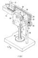
- With reference to FIG. 1 showing a sealing device, the device comprises a
lift frame 11, a pair of front andrear pressure arms 13 movably supported respectively by a pair of front and rearhorizontal pivots 12, and a pair of front andrear sealing jaws 14 opposed to each other and fixed to and projecting from therespective pressure arms 13 each at an upper portion of the arm. - A
vertical drive rod 15 extends through thelift frame 11 and between thepressure arms 13. Thelift frame 11 is coupled to thedrive rod 15 so as to be movable with thedrive rod 15 upward and downward while permitting therod 15 to rotate reversibly. A winglikehorizontal rotary member 16 is fixed to thedrive rod 15. Opposite ends of therotary member 16 are linked to thepressure arms 13 by a pair of connectingrods 17, respectively. - The
drive rod 15 is driven by unillustrated means for upward and downward movements and reversible rotation, whereby the sealingjaws 14 are closed when thelift frame 11 is lowered, and are opened when thelift frame 11 is raised. Unillustrated pressing means produces a sealing pressure between the sealingjaws 14 as closed. - When the tube T is sealed in the form of a bar, the tube is cut transversely thereof at the center of width of the seal portion at the same time by an unillustrated cutter provided on the
front sealing jaw 14. Therear sealing jaw 14 is provided with a U-shaped high-frequency heating coil 18 with an open right end directed sidewise. - Disposed upright at the right of the path of vertical movement of the
lift frame 11 is apost 19 carrying a transmission-sideprimary coil 21 attached to its upper end. A receiving-sidesecondary coil 22 is disposed in the rear of theprimary coil 21. Theprimary coil 21 is provided with a fixedcore 23, and thesecondary coil 22 with amovable core 24. - With reference to FIG. 3, the
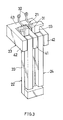
primary coil 21 has a horizontalhelical portion 31 comprising about three turns of wire and extending in the front-to-rear direction. Opposite ends of thehelical portion 31 are provided withrespective terminals 32 for connection to an unillustrated a.c. power source. Thesecondary coil 22 is U-shaped and has a pair ofstraight portions 33 extending vertically in parallel to each other respectively at the right and left sides of the axis of thehelical portion 31. The upper ends of thestraight portions 33 are connected to opposite ends of theheating coil 18 by a pair of connectingcoils 34, respectively (FIG. 1). Thus, a closed electric circuit is formed by thesecondary coil 22, connectingcoils 34 andheating coil 18. - The fixed
core 23 and themovable core 24 are united into a three-leg core as seen in FIG. 4 and are each prepared from ferrite. - The
fixed core 23 is approximately E-shaped when seen from above and comprises ahorizontal leg 41 having thehelical portion 31 fitted therearound, a pair ofouter legs 42 extending in parallel to each other respectively at opposite sides of theleg 41, and ayoke 43 connecting the front ends of theleg 41 and theouter legs 42. Themovable core 24 comprises bars of rectangular cross section extending along the respectivestraight portions 33 and is fixed to the rear faces of thestraight portions 33. - The
secondary coil 22 is moved with themovable core 24 upward, downward and pivotally with the upward and downward movements of thelift frame 11 and the pivotal movement of thepressure arms 13. - FIG. 1 shows the
lift frame 11 at the upper limit of its vertical stroke with the sealingjaws 14 closed. In this state, thestraight portions 33 of theseconary coil 22 and themovable core 24 are positioned in the spaces between theleg 41 of thefixed core 23 and theouter legs 42 thereof as shown in detail in FIG. 4. In this state, theprimary coil 21 and thesecondary coil 22 are interlinked. On the other hand, themovable core 24 forms another yoke of the three-leg core. The primary andsecondary coils lift frame 11 reaches the lower limit of its vertical stroke like the state shown in FIG. 3. - After the
lift frame 11 has been brought to the lower limit, thepressure arms 13 are pivotally moved to open thesealing jaws 14 as shown in FIG. 2. As a result, thesecondary coil 22 is pivotally moved away from theprimary coil 21 with this movement, whereby the primary andsecondary coils - When a high-frequency current is passed through the
primary coil 21 while the primary andsecondary coils secondary coil 22 by the resulting magnetic field. When the current is passed through thehelical portion 31 perpendicular to the plane of FIG. 4 so that the direction of the current is upward at the right side of thehelical portion 31 and downward at the left side of theportion 31, a current flows through thesecondary coil 22, i.e., downward through the rightstraight portion 33 and upward through the leftstraight portion 33, so that the magnetic field of thesecondary coil 22 offsets that of theprimary coil 21. - While the magnitude of the electromotive force induced in the
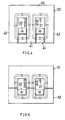
secondary coil 22 is governed by the magnitude of the magnetic field passing between the twostraight portions 33, the magnetic field is effectively guided in between the twostraight portions 33 because thefixed core 23 and themovable core 24 are united into a three-leg core. - Suppose the
movable coil 24 is not used as shown in FIG. 7. The magnetic field set up by theprimary coil 21 will then be reversed before reaching the twostraight portions 33 and will not reach theseportions 33. Thus the primary andsecondary coils - The electromotive force generated in the
secondary coil 22 flows through theheating coil 18, whereby a magnetic field is set up around thecoil 18. The aluminum foil layer of the tube T present between the sealingjaws 14 is induction-heated by the resulting magnetic field. The heat of the aluminum foil layer melts the polyethylene layers outside thereof, and the tube T is heat-sealed at the same time transversely thereof under the pressure of the pressing means acting on the sealingjaws 14. - FIG. 5 shows modified fixed
core 51 andmovable core 52. With this modification, the fixedcore 51, as well as themovable core 52, is approximately E-shaped when seen from above. The fixedcore 51 and themovable core 52 are united into a three-leg core, with the opening portions of one of the cores opposed to those of the other. - FIG. 6 shows other modified fixed
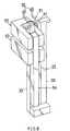
core 53 andmovable core 54. According to this modification, the fixedcore 53 is approximately C-shaped when seen from above, and themovable core 54 is in the form of a bar. The fixedcore 53 and themovable core 54, when united, provide a two-leg core. - The two-leg core is more advantageous to use than the three-leg core in reducing the space needed but is slightly less efficient in electromagnetic induction. To compensate for this, the
primary coil 21 and the fixedcore 53 may be arranged at each of upper and lower two levels as shown in FIG. 8.
Claims (7)
- A sealing device for a packaging material tube of laminate having an aluminum foil layer which device is adapted to seal the tube T transversely thereof and comprises a lift frame (11), a pair of pressure arms (13) supported by the lift frame (11) each at a lower portion thereof and pivotally movable about respective parallel horizontal axes, a pair of sealing jaws (14) opposed to each other and fixed to the respective pressure arms (13) each at an upper portion of the arm, drive means for pivotally moving the pressure arms (13) to close the sealing jaws (14) when the lift frame (11) is lowered and to open the sealing jaws (14) when the lift frame (11) is raised, and a high-frequency heating coil (18) provided on one of the sealing jaws (14) for induction-heating the aluminum foil layer of the tube T present between the sealing jaws (14) as closed, the sealing device being characterized in that the device has a transmission-side primary coil (21) fixedly disposed at one side of the path of vertical movement of the lift frame (11) and a receiving-side secondary coil (22) so provided as to form a closed electric circuit along with the heating coil (18), the primary coil (21) and the secondary coil (22) being electromagnetically connected when the sealing jaws (14) are closed, the primary coil (21) and the secondary coil (22)being electromagnetically separated when the jaws (14) are opened.
- A sealing device for a packaging material tube as defined in claim 1 wherein the primary coil (21) has a horizontal helical portion (31) extending in a direction orthogonal to the axis about which the pressure arm (13) is pivotally movable, and the secondary coil (22) has a pair of straight portions (33)vertically extending respectively at opposite sides of the axis of the helical portion (31), the straight portions (33)being movable toward and away from an end of the helical portion (31) with the pivotal movement of the pressure arms (13).
- A sealing device for a packaging material tube as defined in claim 2 wherein the helical portion (31) has a fixed core(23), and the straight portions (33)are provided with a movable core (24) movable with the straight portions (33), the fixed core (23)and the movable core (24) being united when the sealing jaws (14)are closed to form a closed magnetic circuit extending inside the helical portion (31) and then between the straight portions (33).
- A sealing device for a packaging material tube as defined in claim 3 wherein the fixed core (23)is approximately E-shaped when seen from above and comprises a leg (41) having the helical portion (31) fitted therearound, a pair of outer legs (42) extending in parallel to each other respectively at opposite sides of the leg (31), and a yoke (43)connecting corresponding ends of the leg(41) and the outer legs (42), and the movable core(24)comprises bars extending along the respective straight portions(33) and is fixed to the straight portions (33).
- A sealing device for a packaging material tube as defined in claim 3 wherein the fixed core (51)and the movable core (52)are each approximately E-shaped when seen from above and have their opening portions opposed to each other.
- A sealing device for a packaging material tube as defined in claim 3 wherein the fixed core (53)is approximately C-shaped when seen from above, and the movable core (54)is in the form of a bar.
- A sealing device for a packaging material tube as defined in claim 6 wherein the primary coil (21) and the fixed core (53)are arranged at each of upper and lower two levels.
Applications Claiming Priority (3)
| Application Number | Priority Date | Filing Date | Title |
|---|---|---|---|
| JP57171/95 | 1995-03-16 | ||
| JP05717195A JP3413540B2 (en) | 1995-03-16 | 1995-03-16 | Packaging material tube sealing device |
| JP5717195 | 1995-03-16 |
Publications (3)
| Publication Number | Publication Date |
|---|---|
| EP0732190A2 true EP0732190A2 (en) | 1996-09-18 |
| EP0732190A3 EP0732190A3 (en) | 1998-02-11 |
| EP0732190B1 EP0732190B1 (en) | 2001-12-19 |
Family
ID=13048107
Family Applications (1)
| Application Number | Title | Priority Date | Filing Date |
|---|---|---|---|
| EP19960200724 Expired - Lifetime EP0732190B1 (en) | 1995-03-16 | 1996-03-15 | Sealing device for packaging material tube |
Country Status (6)
| Country | Link |
|---|---|
| US (1) | US5651239A (en) |
| EP (1) | EP0732190B1 (en) |
| JP (1) | JP3413540B2 (en) |
| CN (1) | CN1089673C (en) |
| DE (1) | DE69618049T2 (en) |
| DK (1) | DK0732190T3 (en) |
Cited By (1)
| Publication number | Priority date | Publication date | Assignee | Title |
|---|---|---|---|---|
| US7617658B2 (en) | 2004-11-05 | 2009-11-17 | Tetra Laval Holdings & Finance Sa | Sealing device for producing sealed packages of a pourable food product |
Families Citing this family (7)
| Publication number | Priority date | Publication date | Assignee | Title |
|---|---|---|---|---|
| CN100548810C (en) * | 2005-06-15 | 2009-10-14 | 利乐拉瓦尔集团及财务有限公司 | The apparatus and method that are used for Production and Packaging |
| NL1031167C2 (en) * | 2006-02-16 | 2007-08-17 | Smulders Machine En App Nbouw | Device for joining strips of plastic foil material together. |
| ATE522343T1 (en) * | 2007-06-28 | 2011-09-15 | Tetra Laval Holdings & Finance | INDUCTION SEALING DEVICE FOR HEAT SEALING PACKAGING MATERIAL FOR PRODUCING SEALED PACKAGINGS FOR POURABLE FOOD PRODUCTS |
| EP2520416B9 (en) * | 2011-05-05 | 2014-04-23 | Tetra Laval Holdings & Finance S.A. | Induction sealing device for heat sealing packaging material for producing sealed packages of pourable food products |
| KR101414437B1 (en) * | 2012-05-22 | 2014-07-01 | 오성하이텍(주) | The Cap Sealer of Induction Heating type |
| CN108995905A (en) * | 2017-10-16 | 2018-12-14 | 青岛海科佳电子设备制造有限公司 | A kind of scissor closing device |
| CN110239073A (en) * | 2019-07-19 | 2019-09-17 | 成都斯特睿思科技有限公司 | The sterile tube sealing machine of automatic flat |
Citations (6)
| Publication number | Priority date | Publication date | Assignee | Title |
|---|---|---|---|---|
| US4009068A (en) * | 1975-02-19 | 1977-02-22 | Societe Generale Pour L'emballage | High-frequency bonding apparatus |
| JPS6193011A (en) * | 1984-10-12 | 1986-05-12 | 四国化工機株式会社 | Vessel molding equipment in packaging machine |
| US4637199A (en) * | 1985-01-30 | 1987-01-20 | International Paper Company | Induction sealing of paperboard |
| EP0274641A2 (en) * | 1986-12-17 | 1988-07-20 | International Paper Company | Improved sealing method and apparatus for high capacity aseptic form, fill, and seal machines |
| EP0378880A1 (en) * | 1988-12-22 | 1990-07-25 | Shikoku Kakoki Co., Ltd. | Packaging machine |
| EP0403276A2 (en) * | 1989-06-14 | 1990-12-19 | Toda Kogyo Corp. | Resin-bonding method and heating device for resin-bonding |
Family Cites Families (7)
| Publication number | Priority date | Publication date | Assignee | Title |
|---|---|---|---|---|
| US4163885A (en) * | 1977-09-28 | 1979-08-07 | Illinois Tool Works Inc. | Induction heating core and heating system for adhesive fasteners |
| SE422136B (en) * | 1979-10-23 | 1982-02-15 | Tetra Pak Int | DEVICE FOR SEALING THERMOPLAST COATED PACKAGING MATERIAL |
| JPS57140785A (en) * | 1981-02-24 | 1982-08-31 | Mitsui Toatsu Chem Inc | Benzothiazine derivative, its preparation, and pharmaceutical composition containing the same |
| KR890001585B1 (en) * | 1984-10-12 | 1989-05-09 | 시고꾸 가꼬오끼 가부시끼가이샤 | Apparatus for processing tube for package containers |
| US5109653A (en) * | 1988-06-16 | 1992-05-05 | Continental Holdings Inc. | Sealing head including an induction heating coil |
| US5025123A (en) * | 1988-10-07 | 1991-06-18 | Continental Can Company, Inc. | Apparatus and method for sealing a lid onto a container |
| JPH06193011A (en) * | 1992-12-28 | 1994-07-12 | Howa Mach Ltd | Vibration compacting machine |
-
1995
- 1995-03-16 JP JP05717195A patent/JP3413540B2/en not_active Expired - Fee Related
-
1996
- 1996-03-14 US US08/616,008 patent/US5651239A/en not_active Expired - Fee Related
- 1996-03-15 EP EP19960200724 patent/EP0732190B1/en not_active Expired - Lifetime
- 1996-03-15 DK DK96200724T patent/DK0732190T3/en active
- 1996-03-15 DE DE1996618049 patent/DE69618049T2/en not_active Expired - Fee Related
- 1996-03-15 CN CN96107333A patent/CN1089673C/en not_active Expired - Fee Related
Patent Citations (6)
| Publication number | Priority date | Publication date | Assignee | Title |
|---|---|---|---|---|
| US4009068A (en) * | 1975-02-19 | 1977-02-22 | Societe Generale Pour L'emballage | High-frequency bonding apparatus |
| JPS6193011A (en) * | 1984-10-12 | 1986-05-12 | 四国化工機株式会社 | Vessel molding equipment in packaging machine |
| US4637199A (en) * | 1985-01-30 | 1987-01-20 | International Paper Company | Induction sealing of paperboard |
| EP0274641A2 (en) * | 1986-12-17 | 1988-07-20 | International Paper Company | Improved sealing method and apparatus for high capacity aseptic form, fill, and seal machines |
| EP0378880A1 (en) * | 1988-12-22 | 1990-07-25 | Shikoku Kakoki Co., Ltd. | Packaging machine |
| EP0403276A2 (en) * | 1989-06-14 | 1990-12-19 | Toda Kogyo Corp. | Resin-bonding method and heating device for resin-bonding |
Cited By (1)
| Publication number | Priority date | Publication date | Assignee | Title |
|---|---|---|---|---|
| US7617658B2 (en) | 2004-11-05 | 2009-11-17 | Tetra Laval Holdings & Finance Sa | Sealing device for producing sealed packages of a pourable food product |
Also Published As
| Publication number | Publication date |
|---|---|
| JPH08253203A (en) | 1996-10-01 |
| DK0732190T3 (en) | 2002-03-18 |
| JP3413540B2 (en) | 2003-06-03 |
| US5651239A (en) | 1997-07-29 |
| CN1137011A (en) | 1996-12-04 |
| EP0732190B1 (en) | 2001-12-19 |
| DE69618049T2 (en) | 2002-06-20 |
| DE69618049D1 (en) | 2002-01-31 |
| CN1089673C (en) | 2002-08-28 |
| EP0732190A3 (en) | 1998-02-11 |
Similar Documents
| Publication | Publication Date | Title |
|---|---|---|
| KR960008699B1 (en) | Improved sealing method and apparatus for high capacity aseptic form, fill and seal machines | |
| EP1413520B1 (en) | Sealing jaw | |
| CN106232327B (en) | Induction sealing device and the method for using the induction sealing device sealing and packing material | |
| RU2253599C2 (en) | Method for sealed packages containing pourable food products manufacturing of packing material sleeve and device for above method realization | |
| US5651239A (en) | Sealing device for packaging material tube | |
| EP2021162B1 (en) | Sealing device and method for producing sealed packages of a pourable food product | |
| JPH06298209A (en) | Device to form parallelepiped packing container charged with liquid from tubular packing material web | |
| US4817366A (en) | High capacity package seal, sever, and brick apparatus and method | |
| CN100575056C (en) | Be used to produce the sealed packages of a pourable food product sealing device | |
| EP2520416B9 (en) | Induction sealing device for heat sealing packaging material for producing sealed packages of pourable food products | |
| JP2004502610A (en) | Closed beverage container | |
| US3651299A (en) | Method for sealing containers using heat activated magnetic sealing compound | |
| JPH06183419A (en) | Device for sealing packing material coated with thermoplastics | |
| US6756558B2 (en) | High current, low impedance resistance welding device | |
| US3424885A (en) | Method of producing transverse sealings of collapsible tube-shaped containers by means of pressure jaws and heat,and means for carrying out said method | |
| CA3182484A1 (en) | Plastic spout and pouch packaging | |
| CN106742360A (en) | A kind of packaging facilities | |
| CN217798537U (en) | Pipe sealing machine suitable for sealing pipes with different pipe diameters | |
| CN208699208U (en) | A kind of solid beverage pulvis back seal apparatus | |
| CN114560142A (en) | Fully-hot-melting packaging bag heat sealing machine capable of improving sealing effect |
Legal Events
| Date | Code | Title | Description |
|---|---|---|---|
| PUAI | Public reference made under article 153(3) epc to a published international application that has entered the european phase |
Free format text: ORIGINAL CODE: 0009012 |
|
| AK | Designated contracting states |
Kind code of ref document: A2 Designated state(s): CH DE DK FR GB LI NL SE |
|
| PUAL | Search report despatched |
Free format text: ORIGINAL CODE: 0009013 |
|
| AK | Designated contracting states |
Kind code of ref document: A3 Designated state(s): CH DE DK FR GB LI NL SE |
|
| 17P | Request for examination filed |
Effective date: 19980730 |
|
| 17Q | First examination report despatched |
Effective date: 19991112 |
|
| GRAG | Despatch of communication of intention to grant |
Free format text: ORIGINAL CODE: EPIDOS AGRA |
|
| GRAG | Despatch of communication of intention to grant |
Free format text: ORIGINAL CODE: EPIDOS AGRA |
|
| GRAH | Despatch of communication of intention to grant a patent |
Free format text: ORIGINAL CODE: EPIDOS IGRA |
|
| GRAH | Despatch of communication of intention to grant a patent |
Free format text: ORIGINAL CODE: EPIDOS IGRA |
|
| GRAA | (expected) grant |
Free format text: ORIGINAL CODE: 0009210 |
|
| AK | Designated contracting states |
Kind code of ref document: B1 Designated state(s): CH DE DK FR GB LI NL SE |
|
| REG | Reference to a national code |
Ref country code: CH Ref legal event code: NV Representative=s name: PATENTANWALTSBUERO JEAN HUNZIKER Ref country code: CH Ref legal event code: EP |
|
| REG | Reference to a national code |
Ref country code: GB Ref legal event code: IF02 |
|
| REF | Corresponds to: |
Ref document number: 69618049 Country of ref document: DE Date of ref document: 20020131 |
|
| PGFP | Annual fee paid to national office [announced via postgrant information from national office to epo] |
Ref country code: GB Payment date: 20020307 Year of fee payment: 7 |
|
| REG | Reference to a national code |
Ref country code: DK Ref legal event code: T3 |
|
| PGFP | Annual fee paid to national office [announced via postgrant information from national office to epo] |
Ref country code: CH Payment date: 20020326 Year of fee payment: 7 |
|
| ET | Fr: translation filed | ||
| PLBE | No opposition filed within time limit |
Free format text: ORIGINAL CODE: 0009261 |
|
| STAA | Information on the status of an ep patent application or granted ep patent |
Free format text: STATUS: NO OPPOSITION FILED WITHIN TIME LIMIT |
|
| 26N | No opposition filed | ||
| PG25 | Lapsed in a contracting state [announced via postgrant information from national office to epo] |
Ref country code: GB Free format text: LAPSE BECAUSE OF NON-PAYMENT OF DUE FEES Effective date: 20030315 |
|
| PG25 | Lapsed in a contracting state [announced via postgrant information from national office to epo] |
Ref country code: LI Free format text: LAPSE BECAUSE OF NON-PAYMENT OF DUE FEES Effective date: 20030331 Ref country code: CH Free format text: LAPSE BECAUSE OF NON-PAYMENT OF DUE FEES Effective date: 20030331 |
|
| GBPC | Gb: european patent ceased through non-payment of renewal fee |
Effective date: 20030315 |
|
| REG | Reference to a national code |
Ref country code: CH Ref legal event code: PL |
|
| PGFP | Annual fee paid to national office [announced via postgrant information from national office to epo] |
Ref country code: DK Payment date: 20040123 Year of fee payment: 9 |
|
| PGFP | Annual fee paid to national office [announced via postgrant information from national office to epo] |
Ref country code: DE Payment date: 20040303 Year of fee payment: 9 |
|
| PGFP | Annual fee paid to national office [announced via postgrant information from national office to epo] |
Ref country code: SE Payment date: 20040317 Year of fee payment: 9 |
|
| PGFP | Annual fee paid to national office [announced via postgrant information from national office to epo] |
Ref country code: FR Payment date: 20040329 Year of fee payment: 9 |
|
| PGFP | Annual fee paid to national office [announced via postgrant information from national office to epo] |
Ref country code: NL Payment date: 20040331 Year of fee payment: 9 |
|
| PG25 | Lapsed in a contracting state [announced via postgrant information from national office to epo] |
Ref country code: SE Free format text: LAPSE BECAUSE OF NON-PAYMENT OF DUE FEES Effective date: 20050316 |
|
| PG25 | Lapsed in a contracting state [announced via postgrant information from national office to epo] |
Ref country code: DK Free format text: LAPSE BECAUSE OF NON-PAYMENT OF DUE FEES Effective date: 20050331 |
|
| PG25 | Lapsed in a contracting state [announced via postgrant information from national office to epo] |
Ref country code: NL Free format text: LAPSE BECAUSE OF NON-PAYMENT OF DUE FEES Effective date: 20051001 Ref country code: DE Free format text: LAPSE BECAUSE OF NON-PAYMENT OF DUE FEES Effective date: 20051001 |
|
| EUG | Se: european patent has lapsed | ||
| PG25 | Lapsed in a contracting state [announced via postgrant information from national office to epo] |
Ref country code: FR Free format text: LAPSE BECAUSE OF NON-PAYMENT OF DUE FEES Effective date: 20051130 |
|
| NLV4 | Nl: lapsed or anulled due to non-payment of the annual fee |
Effective date: 20051001 |
|
| REG | Reference to a national code |
Ref country code: DK Ref legal event code: EBP |
|
| REG | Reference to a national code |
Ref country code: FR Ref legal event code: ST Effective date: 20051130 |