EP0732177B1 - Screw tightening machine - Google Patents
Screw tightening machine Download PDFInfo
- Publication number
- EP0732177B1 EP0732177B1 EP96250063A EP96250063A EP0732177B1 EP 0732177 B1 EP0732177 B1 EP 0732177B1 EP 96250063 A EP96250063 A EP 96250063A EP 96250063 A EP96250063 A EP 96250063A EP 0732177 B1 EP0732177 B1 EP 0732177B1
- Authority
- EP
- European Patent Office
- Prior art keywords
- nose
- magazine
- screws
- screw
- main body
- Prior art date
- Legal status (The legal status is an assumption and is not a legal conclusion. Google has not performed a legal analysis and makes no representation as to the accuracy of the status listed.)
- Expired - Lifetime
Links
Images

Classifications
-
- B—PERFORMING OPERATIONS; TRANSPORTING
- B25—HAND TOOLS; PORTABLE POWER-DRIVEN TOOLS; MANIPULATORS
- B25C—HAND-HELD NAILING OR STAPLING TOOLS; MANUALLY OPERATED PORTABLE STAPLING TOOLS
- B25C1/00—Hand-held nailing tools; Nail feeding devices
- B25C1/001—Nail feeding devices
- B25C1/003—Nail feeding devices for belts of nails
-
- B—PERFORMING OPERATIONS; TRANSPORTING
- B25—HAND TOOLS; PORTABLE POWER-DRIVEN TOOLS; MANIPULATORS
- B25B—TOOLS OR BENCH DEVICES NOT OTHERWISE PROVIDED FOR, FOR FASTENING, CONNECTING, DISENGAGING OR HOLDING
- B25B23/00—Details of, or accessories for, spanners, wrenches, screwdrivers
- B25B23/02—Arrangements for handling screws or nuts
- B25B23/04—Arrangements for handling screws or nuts for feeding screws or nuts
- B25B23/045—Arrangements for handling screws or nuts for feeding screws or nuts using disposable strips or discs carrying the screws or nuts
Definitions
- This invention relates to a screw tightening machine according to the precharacterizing part of the claim.
- a magazine described in, for example, Japanese Patent Official Gazette No. Hei 1-60395 is known as an example for use in this type of screw tightening machine.
- This magazine is fixed to the body of a screw tightening machine and, inside of the magazine, a path along which a string of screws are guided is provided so that the screws are stably kept to smoothly carry out a screw tightening operation.
- the screw tightening machine has a nose capable of, with respect to the body of the machine, moving in a direction in which a screw is tightened.
- the nose can protrude from or retract into the body of the machine.
- the screws kept in the magazine are fed to the nose.
- the nose to which the screws are fed moves relatively with respect to the body of the machine during the screw tightening operation, whereas the magazine from which the screws are fed is unmovably fixed to the body.
- the screws 23 in the magazine 22 are pulled out of the magazine 22 when the nose 20 moves forwards as shown in Fig. 3, whereas the screws 23 are pulled into the magazine 22 when the nose 20 retracts as shown by the broken line in Fig. 3.
- the screws 23 move in the magazine 22 because of a pull and a push by the nose 20. This movement causes some difficulty in carrying out the screw tightening operation.
- US-A-4 014 225 discloses a screw tightening apparatus comprising a motor-driven tool, a magazine for screws affixed to a strip-like carrier, and a screw advancing and tightening means for advancing the screws one at a time to a preparatory screw tightening position allowing a bit portion of the motor-driven tool to engage with the screw for tightening thereof.
- the screw advancing and tightening means comprises two axially movable portions, the first one of which is secured to the tool and the second one of which carries the magazine.
- the magazine is fixed to only the second axially movable portion and has no connection to the first axially movable portion.
- DE-A-41 19 925 describes a screw tightening machine comprising a main body, an adapter removably secured on a forward part of the main body, a nose mounted on a forward part of the main body, which nose is capable of being moved relatively with respect to the adapter in a direction in which a screw is tightened, the screw being driven out from the nose, and a magazine for guiding and feeding a band in which the screws spaced away from each other at predetermined intervals are fitted to the nose.
- the magazine is fixed to the adapter and to the main body.
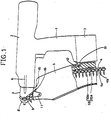
- Fig. 1 is a side view showing a screw tightening machine according to the present invention.
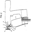
- Fig. 2 is a descriptive drawing of the screw tightening machine in operation.
- Fig. 3 is a side view showing a conventional screw tightening machine.
- the screw tightening machine comprises a main body 2 formed integrally with a grip 1, a nose 3 mounted on the forward part of the main body 2 so as to move relatively with respect to a direction in which a screw is tightened, and a magazine 5 from which a string of screws (chained screws) 4 are fed to the nose 3.
- An inlet 15 for the screws is formed in the lower surface of the nose 3, and an outlet 16 for the screws is formed in the upper surface of the magazine 5.
- the screw set (chained screws) 4 comprises a band 4a and screws 4b evenly spaced in the band 4a.
- the screws 4b are removable from the band 4a.
- the main body 2 has a driver bit 6 and a driving mechanism (not shown) for turning the driver bit 6.
- a driving mechanism (not shown) for turning the driver bit 6.
- the nose 3 is hollow and has a striking part 8 and a passageway 9 for the chained screws 4.
- the striking part 8 is formed on an extension line of an axis of the driver bit 6.
- the passageway 9 passes through the striking part 8 from the lower part to the upper part of the nose 3.
- a feed mechanism (not shown) is provided for conveying the chained screws 4 along the passageway 9 upwards and feeding a screw 4b of the chained screws 4 to the striking part 8.
- the feed mechanism (not shown) is designed to feed a screw 4b to be subsequently driven out to the striking part 8 by conveying the chained screws 4 when the nose 3 moves relatively with the main body 2 of the machine.
- the force of a spring is always applied to the nose 3 in a direction in which the screw 4b is driven out with respect to the main body 2. As a result, the nose 3 is in a state of protrusion from the main body 2.
- the magazine 5 is hollow and, in the hollow part, has a passageway 10 by which the chained screws 4 are kept drawn toward the side of the grip 1 and are guided to the nose 3. Following the passageway 10, the chained screws 4 are fed to the nose 3 through the outlet 16 and the inlet 15.
- the passageway 10 comprises a passage (not shown) for the band 4a, a passage 10a for a head of the screw 4b, and a passage 10b for a thread part of the screw 4b.
- the upper part of the magazine 5 is rotatably fixed to a link 11 mounted on the lower part of the nose 3.
- a slit 12 is formed which elongates in up and down directions.
- a shaft 13 of the grip 1 is inserted into the slit 12 and is relatively slid along the slit 12.
- the driver bit 6 when the end of the nose 3 is pressed against a piece of material 14 into which a screw 4b is screwed and, in addition, the nose 3 is pushed to the main body 2 against the resilient force of the spring, the driver bit 6 relatively approaches the screw 4b situated in the striking part 8 of the nose 3.
- the driver bit 6 By pushing the nose 3 still more, the driver bit 6 is brought into contact with the screw 4b and is turned by the driving mechanism (not shown). With the driver bit 6 engaged with a groove of the head of the screw 4b, the screw 4b is turned. The screw 4b is taken off from the band 4a while turning. The screw 4b is then driven out from the end of the nose 3 and is screwed into the material 14.
- the nose 3 again protrudes from the main body 2 of the machine by means of the resilient force of the spring and returns to its initial position shown in Fig. 1.
- the nose 3 thus moves relatively with the main body 2
- the chained screws 4 in the passageway 9 of the nose 3 are conveyed by the feed mechanism.
- a screw 4b to be subsequently driven out is fed to the striking part 8 for the following tightening operation.
- the chained screws 4 in the magazine 5 are conveyed to the nose 3.
- the nose 3 moves relatively with the main body 2 of the machine whenever the screw tightening operation is carried out.
- the shaft 13 of the grip 1 is slidably inserted in the slit 12 formed in the lower part of the magazine 5, the upper part of the magazine 5 can move in unison with the movement of the nose 3. Therefore, there is not any fear that the chained screws 4 in the magazine 5 unnecessarily move according to the movement of the nose 3.
- the feed mechanism is actuated in response to the relative movement of the nose 3 so that screws 4b are fed to the striking part 8 one by one, but the quantity of movement of the chained screws 4 per screw 4b is utterly negligible in the operation.
Description
Claims (1)
- A screw tightening machine comprising:a main body (2) formed on an upper end of a grip (1) extending downwardly from the main body (2);a nose (3) mounted on a forward part of said main body (2), said nose (3) being capable of moving forwardly and backwardly relative to the main body (2) in longitudinal direction of a screw (4b) which is to be driven out from said nose (3) and tightened; anda magazine (5) for guiding and feeding a band (4a), in which screws are fitted evenly spaced from each other, to said nose (3);
characterized in that:an upper end of said magazine (5) is rotatably connected to said nose (3); andin that a side of a lower part of said magazine (5) is slidably connected to said grip (1) so that the lower part of said magazine (5) can slide upwardly and downwardly along said grip (1) while the upper end of said magazine (5) is moving in unison with the movement of said nose (3).
Applications Claiming Priority (2)
| Application Number | Priority Date | Filing Date | Title |
|---|---|---|---|
| JP7083186A JP2904336B2 (en) | 1995-03-15 | 1995-03-15 | Screw tightening machine |
| JP83186/95 | 1995-03-15 |
Publications (2)
| Publication Number | Publication Date |
|---|---|
| EP0732177A1 EP0732177A1 (en) | 1996-09-18 |
| EP0732177B1 true EP0732177B1 (en) | 1998-09-16 |
Family
ID=13795299
Family Applications (1)
| Application Number | Title | Priority Date | Filing Date |
|---|---|---|---|
| EP96250063A Expired - Lifetime EP0732177B1 (en) | 1995-03-15 | 1996-03-14 | Screw tightening machine |
Country Status (4)
| Country | Link |
|---|---|
| US (1) | US5664468A (en) |
| EP (1) | EP0732177B1 (en) |
| JP (1) | JP2904336B2 (en) |
| DE (1) | DE69600646T2 (en) |
Families Citing this family (4)
| Publication number | Priority date | Publication date | Assignee | Title |
|---|---|---|---|---|
| JP4891061B2 (en) * | 2006-12-28 | 2012-03-07 | 株式会社マキタ | Screw feeder of screw tightening machine |
| US7487699B2 (en) * | 2007-03-06 | 2009-02-10 | Xu Jun-Xiu | Screw fastening device |
| TW201020070A (en) * | 2008-11-20 | 2010-06-01 | chong-yuan He | Assembly of collated screw and screw gun |
| CN106425964B (en) * | 2016-09-30 | 2018-01-19 | 国网山东省电力公司商河县供电公司 | A kind of screwdriver suitable for full material screw with storage staple cartridge |
Family Cites Families (13)
| Publication number | Priority date | Publication date | Assignee | Title |
|---|---|---|---|---|
| US2943652A (en) * | 1955-12-06 | 1960-07-05 | Gen Motors Corp | Power operated tool for feeding and driving headed fasteners |
| GB1206948A (en) * | 1966-12-07 | 1970-09-30 | Gaston E Marbaix Ltd | Improvements in or relating to nail and like magazines for fastener driving tools |
| US3615049A (en) * | 1969-09-15 | 1971-10-26 | Fastener Corp | Fastener driving tool |
| DE2027642A1 (en) * | 1970-06-05 | 1971-12-09 | C.& E. Fein, 7000 Stuttgart | Motor-driven screwdriver hand tool |
| US4014225A (en) * | 1973-02-02 | 1977-03-29 | Bulten-Kanthal Aktiebolag | Power-driven screwdriver |
| GB1430097A (en) * | 1973-03-13 | 1976-03-31 | Gkn Screws Fasteners Ltd | Fastener feed for power tools |
| US4014488A (en) * | 1973-11-05 | 1977-03-29 | Duo-Fast Corporation | Fastener feed apparatus and method |
| US3907014A (en) * | 1974-04-29 | 1975-09-23 | Anthony P Manino | Mechanism for feeding and driving screws |
| US4667545A (en) * | 1985-06-03 | 1987-05-26 | Gould Jr Frederick H | Screw gun automatic feed |
| US4778094A (en) * | 1987-10-02 | 1988-10-18 | The Dimpling Nailing Gun Company | Nail and dimpler driving apparatus for nailing gun |
| JPH02232178A (en) * | 1989-03-06 | 1990-09-14 | Masaki Kawashima | Fastener tightening machine |
| US5101697A (en) * | 1990-03-26 | 1992-04-07 | Plenum Corporation | Drywall screw dispensing and driving gun |
| CA2044088A1 (en) * | 1990-06-18 | 1991-12-19 | Takeo Fujiyama | Screw driving machine with a belt support and guidance mechanism |
-
1995
- 1995-03-15 JP JP7083186A patent/JP2904336B2/en not_active Expired - Lifetime
-
1996
- 1996-03-14 DE DE69600646T patent/DE69600646T2/en not_active Expired - Fee Related
- 1996-03-14 EP EP96250063A patent/EP0732177B1/en not_active Expired - Lifetime
- 1996-03-15 US US08/616,270 patent/US5664468A/en not_active Expired - Fee Related
Also Published As
| Publication number | Publication date |
|---|---|
| US5664468A (en) | 1997-09-09 |
| EP0732177A1 (en) | 1996-09-18 |
| JPH08252777A (en) | 1996-10-01 |
| JP2904336B2 (en) | 1999-06-14 |
| DE69600646T2 (en) | 1999-05-12 |
| DE69600646D1 (en) | 1998-10-22 |
Similar Documents
| Publication | Publication Date | Title |
|---|---|---|
| US5031489A (en) | Control means for fastener driving device | |
| US4428261A (en) | Screw feed apparatus for use with a power screwdriving tool | |
| US4404877A (en) | Power-driven screwdriver | |
| JP4694844B2 (en) | Auto-feed screwdriver for driving connecting screws | |
| US6109144A (en) | Successive screw feeder driver | |
| AU702558B2 (en) | Screwdriver with replaceable nose for collated screws | |
| US5927163A (en) | Screwdriver with slotted nose for collated screws | |
| US6601480B1 (en) | Autofeed screwdriver for screws with flat head bottoms | |
| SE461509B (en) | ENGINE DRIVE SCREW DRIVER WITH SUCCESSIVE FEED | |
| US5870933A (en) | Advance mechanism for collated screwdriver | |
| US3587683A (en) | Automatic screwdriver | |
| US5370290A (en) | Wire feeder allowing for wire slippage without damaging wire | |
| EP0732177B1 (en) | Screw tightening machine | |
| US4667545A (en) | Screw gun automatic feed | |
| US4862928A (en) | Single cable tie loading gate assembly for an automatic cable tie installation tool | |
| CA2172429A1 (en) | Riveting apparatus | |
| US5899126A (en) | Screw tightener | |
| JP3976786B2 (en) | Power drill housing extension coupling | |
| US4969582A (en) | Apparatus for feeding an elongated fastener to a fastening tool, especially for feeding a stud in a stud welder | |
| US5370295A (en) | Feed mechanism for gravity feed tackers | |
| CA2209676C (en) | Successive screw feeder driver | |
| EP0532819B1 (en) | A screw positioning and feeding device | |
| JPH06297350A (en) | Screwing machine for screw retained by belt | |
| US5236271A (en) | Automatic mechanical pencil | |
| EP1401715A4 (en) | System for dispensing plastic fasteners |
Legal Events
| Date | Code | Title | Description |
|---|---|---|---|
| PUAI | Public reference made under article 153(3) epc to a published international application that has entered the european phase |
Free format text: ORIGINAL CODE: 0009012 |
|
| AK | Designated contracting states |
Kind code of ref document: A1 Designated state(s): DE FR GB |
|
| 17P | Request for examination filed |
Effective date: 19960905 |
|
| 17Q | First examination report despatched |
Effective date: 19970507 |
|
| GRAG | Despatch of communication of intention to grant |
Free format text: ORIGINAL CODE: EPIDOS AGRA |
|
| GRAG | Despatch of communication of intention to grant |
Free format text: ORIGINAL CODE: EPIDOS AGRA |
|
| GRAH | Despatch of communication of intention to grant a patent |
Free format text: ORIGINAL CODE: EPIDOS IGRA |
|
| GRAH | Despatch of communication of intention to grant a patent |
Free format text: ORIGINAL CODE: EPIDOS IGRA |
|
| GRAA | (expected) grant |
Free format text: ORIGINAL CODE: 0009210 |
|
| AK | Designated contracting states |
Kind code of ref document: B1 Designated state(s): DE FR GB |
|
| REF | Corresponds to: |
Ref document number: 69600646 Country of ref document: DE Date of ref document: 19981022 |
|
| ET | Fr: translation filed | ||
| PLBE | No opposition filed within time limit |
Free format text: ORIGINAL CODE: 0009261 |
|
| STAA | Information on the status of an ep patent application or granted ep patent |
Free format text: STATUS: NO OPPOSITION FILED WITHIN TIME LIMIT |
|
| 26N | No opposition filed | ||
| REG | Reference to a national code |
Ref country code: GB Ref legal event code: IF02 |
|
| PGFP | Annual fee paid to national office [announced via postgrant information from national office to epo] |
Ref country code: GB Payment date: 20030303 Year of fee payment: 8 |
|
| PGFP | Annual fee paid to national office [announced via postgrant information from national office to epo] |
Ref country code: FR Payment date: 20030326 Year of fee payment: 8 |
|
| PGFP | Annual fee paid to national office [announced via postgrant information from national office to epo] |
Ref country code: DE Payment date: 20030331 Year of fee payment: 8 |
|
| PG25 | Lapsed in a contracting state [announced via postgrant information from national office to epo] |
Ref country code: GB Free format text: LAPSE BECAUSE OF NON-PAYMENT OF DUE FEES Effective date: 20040314 |
|
| PG25 | Lapsed in a contracting state [announced via postgrant information from national office to epo] |
Ref country code: DE Free format text: LAPSE BECAUSE OF NON-PAYMENT OF DUE FEES Effective date: 20041001 |
|
| GBPC | Gb: european patent ceased through non-payment of renewal fee |
Effective date: 20040314 |
|
| PG25 | Lapsed in a contracting state [announced via postgrant information from national office to epo] |
Ref country code: FR Free format text: LAPSE BECAUSE OF NON-PAYMENT OF DUE FEES Effective date: 20041130 |
|
| REG | Reference to a national code |
Ref country code: FR Ref legal event code: ST |