EP0731480A2 - CAM follower assembly for use in a latching switch - Google Patents
CAM follower assembly for use in a latching switch Download PDFInfo
- Publication number
- EP0731480A2 EP0731480A2 EP96300238A EP96300238A EP0731480A2 EP 0731480 A2 EP0731480 A2 EP 0731480A2 EP 96300238 A EP96300238 A EP 96300238A EP 96300238 A EP96300238 A EP 96300238A EP 0731480 A2 EP0731480 A2 EP 0731480A2
- Authority
- EP
- European Patent Office
- Prior art keywords
- cam follower
- cam
- assembly
- spring
- switch
- Prior art date
- Legal status (The legal status is an assumption and is not a legal conclusion. Google has not performed a legal analysis and makes no representation as to the accuracy of the status listed.)
- Granted
Links
Images

Classifications
-
- H—ELECTRICITY
- H01—ELECTRIC ELEMENTS
- H01H—ELECTRIC SWITCHES; RELAYS; SELECTORS; EMERGENCY PROTECTIVE DEVICES
- H01H13/00—Switches having rectilinearly-movable operating part or parts adapted for pushing or pulling in one direction only, e.g. push-button switch
- H01H13/50—Switches having rectilinearly-movable operating part or parts adapted for pushing or pulling in one direction only, e.g. push-button switch having a single operating member
- H01H13/56—Switches having rectilinearly-movable operating part or parts adapted for pushing or pulling in one direction only, e.g. push-button switch having a single operating member the contact returning to its original state upon the next application of operating force
- H01H13/562—Switches having rectilinearly-movable operating part or parts adapted for pushing or pulling in one direction only, e.g. push-button switch having a single operating member the contact returning to its original state upon the next application of operating force making use of a heart shaped cam
Definitions
- the present invention is directed generally to electrical switches and, more specifically, to a cam follower assembly for use in push-push type latching switch assemblies.
- Push-push type latching switches which control actuation of an electrical function are well known in the automotive industry.
- push-push type latching switches could be described as switches in which the switch is normally biased to an "off” position. The switch may be pushed inwardly, and is then returned slightly rearwardly to an “on” position. The switch remains at rest in this "on” position. When one desires to turn the switch back to the “off” position the switch is again pressed inwardly, and at that time the switch returns fully to the “off” position.
- Various methods of achieving this movement have been utilized in the prior art.
- a cam follower rides along a heart-shaped cam surface located in a latching switch assembly.
- the cam follower begins movement along a first face of the cam surface as the switch moves from the "off” position inwardly on a first depression of the switch. Once the switch is fully depressed, the cam follower is at the end of that first surface of the cam surface.
- a spring bias force then forces the cam follower into a trough, where it is retained. The cam follower secures the cam surface, and thus the switch button at this position spaced inwardly from the "off” position. This is the "on” position.
- the cam follower In such prior art assemblies, the cam follower must be spring biased to a particular position relative to the housing which receives the cam follower.
- the cam follower In the prior art, the cam follower has typically been a finger at the end of a torsion spring.
- the torsion spring has been mounted in the housing, and the cam follower has performed its movement along the cam surface.
- the torsion spring biases the cam follower as is required.
- precise positioning and manufacture of the cam follower are required. With any variation in the mounting, positioning or manufacture of the torsion spring and cam follower, the movement of the cam follower along the cam surface will not be as required for operation of the switch.
- the above-described limitations in such push-push type latching switches have, heretofore, not been addressed.
- the invention herein solves the above-identified limitations and provides a superior latching switch assembly.
- a cam follower is disposed in the case and has a shaft movable within the slot.
- a spring disposed in the case adjacent the cam follower biases the cam follower toward a longitudinal axis of the case.
- the present invention improves upon the prior art cam followers by utilizing the slot to guide movement of the cam follower.
- a C-shaped spring having two arms surrounds the cam follower. The two arms bias the cam follower back towards an axis of the housing at which it is desired for the cam follower to rest in a relaxed position. Since the C-shaped spring may be easily positioned within the housing, precise positioning of the cam follower or spring is not required. Moreover, slight manufacturing differences in the spring or cam follower do not affect the operation of the overall system. Also, the slot limits movement of the cam follower relative to the spring along an axial direction. Without the slot, the cam follower would be free to move axially between the two legs of the C-shaped spring.
- the housing which receives the cam follower and the spring is an enclosed housing formed by two opposed walls connected by a living hinge.
- the living hinge housing is easily and quickly assembled by snapping an attachment element on one of the walls into a channel in the other of the two walls.
- a latching switch assembly 20 includes a latching switch button 22, a latching switch body 24, a cam assembly 26 and cam follower assembly 28.
- Switch button 22 has legs 29 received in channel 30 of latching switch body 24, with springs 32 biasing switch button 22 away from latching switch body 24.
- This invention relates to innovations in cam follower assembly 28. Even so, the remainder of one switch embodiment will be described in detail to provide an explanation of the function of the cam follower assembly 28. It should be understood that this invention extends to other switch types, and that the specifically disclosed switch is not limiting on the invention.
- Cam assembly 26 includes electrical connection arms 34 which contact circuit elements on a circuit board (not shown in this figure). Cam assembly 26 is fixed to move with button 22. By depressing switch button 22, cam assembly 26 is moved, thereby sliding electrical connection arms 34 across circuit elements of a circuit board to control an electrical function. Cam follower 38 of cam assembly 28 cooperates with a cam surface 35 of cam assembly 26 to lock cam assembly at "on” and “off” positions and locate electrical connection arms 34 along the circuit board, as will be described below.
- cam follower assembly 28 includes a case 36, a cam follower 38 and a symmetric, C-shaped cam spring 40.
- Case 36 includes opposed walls 42 and 44 connected by a living hinge 46.
- Case 36 is preferably made of known thermosetting plastic material, with living hinge 46 and walls 42 and 44 integrally forming a housing.
- First wall 42 includes a slot 48 which receives and guides shaft 50 of cam follower 38.
- second wall 44 includes attachment elements 52 which are received in channel 54 formed in first wall 42.
- cam follower 38 and cam spring 40 are received within case 36.
- Shaft 50 is received in slot 48 and spring arms 41 and 43 of cam spring 40 are disposed on either side cam follower 38.
- Case 36 is bent at living hinge 46, with attachment elements snapped into channel 54 enclosing the housing of cam follower assembly 38. Shaft 50 extends through slot 48, and beyond wall 42.
- cam spring 40 and cam follower 38 are received in case 36 with shaft 50 of cam follower 38 received in slot 48 and arms 41 and 43 of cam spring 40 adjacent cam follower 38.
- Spring 40 has in a plane perpendicular to post 50 of cam follower 38. Spring 40 is simply snapped over post 39. Thus, it is relatively easy to ensure proper placement of the spring 40, due to post 39.
- Arms 41 and 43 bias cam follower 38 back toward longitudinal axis C should cam follower 38 move away from axis C. With movement in one direction, arm 43 of spring 40 biases cam follower 38 toward axis C. With movement in the other direction, arm 41 of spring 40 biases cam follower 38 toward axis C.
- slot 48 will allow movement of shaft 50 to either lateral side of axis C.
- post 50 would extend from the plane of the paper of this figure, but is shown in the figure for clarity.
- Post 50 of cam follower 38 cooperates with cam surface 35 in a manner which displaces post 50 from longitudinal axis C, as will be described below.
- the arms 41 and 43 bias the cam follower 38 back toward axis C.
- switch button 22 A second depression of switch button 22 displaces switch button 22 a distance Y from second position 22c back to first position 22b.
- springs 32 bias switch button 22 away from latching switch body 24 back to initial position 22a.
- the switch button 22 is displaced a net distance Z.
- cam follower spring 40 biases cam follower 38 and shaft 50 back toward longitudinal axis C. Once reaching position 50e, this bias force returns cam follower 38 to position 50a. Throughout this entire movement, slot 48 guides shaft 50.
- cam follower spring 40 is able to bias cam follower 38 and shaft 50 toward a longitudinal axis C in both lateral directions.
- Slot 48 is preferably between an angle of 0° to about 30°, as measured from an axis perpendicular to the longitudinal axis C. In one preferred embodiment, the slot is at an angle of about 10°. Slot 48 guides movement of shaft 50 of cam follower 38 as it moves along cam surface 35. Slot 48 also limits movement of cam follower 38 relative to spring 40 by preventing cam follower 38 from moving axially between legs 41 and 43 through the housing of cam follower assembly 28.
Landscapes
- Push-Button Switches (AREA)
- Mechanisms For Operating Contacts (AREA)
Abstract
Description
- The present invention is directed generally to electrical switches and, more specifically, to a cam follower assembly for use in push-push type latching switch assemblies.
- Push-push type latching switches which control actuation of an electrical function are well known in the automotive industry. In general, push-push type latching switches could be described as switches in which the switch is normally biased to an "off" position. The switch may be pushed inwardly, and is then returned slightly rearwardly to an "on" position. The switch remains at rest in this "on" position. When one desires to turn the switch back to the "off" position the switch is again pressed inwardly, and at that time the switch returns fully to the "off" position. Various methods of achieving this movement have been utilized in the prior art.
- In one recent latching assembly for latching the switch at the "on" position and allowing it to be released back to the "off" position upon release, a cam follower rides along a heart-shaped cam surface located in a latching switch assembly. The cam follower begins movement along a first face of the cam surface as the switch moves from the "off" position inwardly on a first depression of the switch. Once the switch is fully depressed, the cam follower is at the end of that first surface of the cam surface. A spring bias force then forces the cam follower into a trough, where it is retained. The cam follower secures the cam surface, and thus the switch button at this position spaced inwardly from the "off" position. This is the "on" position. In the "on" position electrical contacts associated with the switch are in a position on a circuit board where an electrical circuit is made and a vehicle function is actuated. When one desires to move the switch back to the "off" position, the switch is again depressed inwardly. The cam follower moves out of the trough and begins movement along a second surface. Eventually, the cam follower returns to its initial position.
- In such prior art assemblies, the cam follower must be spring biased to a particular position relative to the housing which receives the cam follower. In the prior art, the cam follower has typically been a finger at the end of a torsion spring. The torsion spring has been mounted in the housing, and the cam follower has performed its movement along the cam surface. The torsion spring biases the cam follower as is required. However, with this type of prior art system, precise positioning and manufacture of the cam follower are required. With any variation in the mounting, positioning or manufacture of the torsion spring and cam follower, the movement of the cam follower along the cam surface will not be as required for operation of the switch.
- The above-described limitations in such push-push type latching switches have, heretofore, not been addressed. The invention herein solves the above-identified limitations and provides a superior latching switch assembly.
- In a disclosed embodiment of the invention, a cam follower assembly for use in a latching switch assembly comprises a case having at least one wall with a slot in the wall. A cam follower is disposed in the case and has a shaft movable within the slot. A spring disposed in the case adjacent the cam follower biases the cam follower toward a longitudinal axis of the case.
- The present invention improves upon the prior art cam followers by utilizing the slot to guide movement of the cam follower. In addition, a C-shaped spring having two arms surrounds the cam follower. The two arms bias the cam follower back towards an axis of the housing at which it is desired for the cam follower to rest in a relaxed position. Since the C-shaped spring may be easily positioned within the housing, precise positioning of the cam follower or spring is not required. Moreover, slight manufacturing differences in the spring or cam follower do not affect the operation of the overall system. Also, the slot limits movement of the cam follower relative to the spring along an axial direction. Without the slot, the cam follower would be free to move axially between the two legs of the C-shaped spring.
- In a further feature of this invention, the housing which receives the cam follower and the spring is an enclosed housing formed by two opposed walls connected by a living hinge. The living hinge housing is easily and quickly assembled by snapping an attachment element on one of the walls into a channel in the other of the two walls.
- These and other features of the present invention will be best understood from the following specifications and drawings, of which the following is a brief description.
-
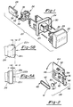
- Figure 1 is an exploded, perspective view of a latching switch assembly including a cam follower assembly in accordance with the invention herein;
- Figure 2 is an exploded, perspective view of the cam follower assembly of Figure 1 ;
- Figure 3 is a partially sectional elevation view of the latching switch assembly of Figure 1;
- Figure 4 is a cross-sectional view of the cam follower assembly of Figure 3 along line 4-4;
- Figures 5A and 5B are side elevational views of the latching switch button of Figure 3; and
- Figure 6 is a cross-sectional view of the cam surface of Figure 3 along line 6-6.
- A
latching switch assembly 20 includes alatching switch button 22, alatching switch body 24, acam assembly 26 andcam follower assembly 28.Switch button 22 haslegs 29 received inchannel 30 oflatching switch body 24, withsprings 32biasing switch button 22 away fromlatching switch body 24. This invention relates to innovations incam follower assembly 28. Even so, the remainder of one switch embodiment will be described in detail to provide an explanation of the function of thecam follower assembly 28. It should be understood that this invention extends to other switch types, and that the specifically disclosed switch is not limiting on the invention. -
Cam assembly 26 includeselectrical connection arms 34 which contact circuit elements on a circuit board (not shown in this figure).Cam assembly 26 is fixed to move withbutton 22. Bydepressing switch button 22,cam assembly 26 is moved, thereby slidingelectrical connection arms 34 across circuit elements of a circuit board to control an electrical function.Cam follower 38 ofcam assembly 28 cooperates with acam surface 35 ofcam assembly 26 to lock cam assembly at "on" and "off" positions and locateelectrical connection arms 34 along the circuit board, as will be described below. - As shown in Figure 2,
cam follower assembly 28 includes acase 36, acam follower 38 and a symmetric, C-shaped cam spring 40.Case 36 includesopposed walls living hinge 46.Case 36 is preferably made of known thermosetting plastic material, withliving hinge 46 andwalls First wall 42 includes aslot 48 which receives and guidesshaft 50 ofcam follower 38. For ease of assembly,second wall 44 includesattachment elements 52 which are received inchannel 54 formed infirst wall 42. When assembled,cam follower 38 andcam spring 40 are received withincase 36. Shaft 50 is received inslot 48 andspring arms cam spring 40 are disposed on eitherside cam follower 38.Case 36 is bent atliving hinge 46, with attachment elements snapped intochannel 54 enclosing the housing ofcam follower assembly 38.Shaft 50 extends throughslot 48, and beyondwall 42. - As shown in Figure 3, post 56 of
cam follower assembly 28 is received inaperture 25, fixing the cam follower assembly to latchingswitch body 24.Shaft 50 ofcam follower 38 is received in a channel formed bycam surface 35 ofcam body 26.Circuit board 57 is shown schematically in this figure. When mounted in a vehicle some structure may be positioned rearwardly ofcam follower assembly 28 holding it against to switchbody 24. An outer surface offirst wall 42 is positioned adjacent anend surface 35x ofcam assembly 26.Shaft 50 moves in a plane parallel to the plane ofcam surface 35x in a two dimensional fashion. As will be explained, successive depressions ofswitch button 22 actuatescam body 26 which moveselectrical connection arms 34 alongcircuit board 57, thereby controlling an electrical switch.Case 36 ofcam follower assembly 28 does not move withswitch button 22 orcam assembly 26, but remains static with latchingswitch body 24. - As shown in Figure 4,
cam spring 40 andcam follower 38 are received incase 36 withshaft 50 ofcam follower 38 received inslot 48 andarms cam spring 40adjacent cam follower 38.Spring 40 has in a plane perpendicular to post 50 ofcam follower 38.Spring 40 is simply snapped overpost 39. Thus, it is relatively easy to ensure proper placement of thespring 40, due to post 39.Arms bias cam follower 38 back toward longitudinal axis C shouldcam follower 38 move away from axis C. With movement in one direction,arm 43 ofspring 40biases cam follower 38 toward axis C. With movement in the other direction,arm 41 ofspring 40biases cam follower 38 toward axis C. As shown,slot 48 will allow movement ofshaft 50 to either lateral side of axis C. In practice, post 50 would extend from the plane of the paper of this figure, but is shown in the figure for clarity.Post 50 ofcam follower 38 cooperates withcam surface 35 in a manner which displaces post 50 from longitudinal axis C, as will be described below. Thearms cam follower 38 back toward axis C. - As shown in Figure 5A, when an operator depresses
switch button 22 from an initial "off"position 22a (shown in phantom), aswitch button 22 is displaced a lateral distance X to a first position 22b (also shown in phantom). Inposition 22a, theelectrical connection arms 34 are not in a position oncircuit board 57 to actuate the controlled function. Upon releasing theswitch button 22, springs 32bias switch button 22 away from latchingswitch body 24, thereby displacingswitch button 22 a distance Y from first position 22b tosecond position 22c. Atposition 22c,push button 22 remains in an "on" position, which is a distance Z from the initial "off"position 22a (see Figure 5B). Inposition 22c, theelectrical connection arms 34 are in a position oncircuit board 57 to actuate some function. As will be explained, thecam follower 38 locks the switch atposition 22c. - A second depression of
switch button 22 displaces switchbutton 22 a distance Y fromsecond position 22c back to first position 22b. Upon releasing the button from position 22b, springs 32bias switch button 22 away from latchingswitch body 24 back toinitial position 22a. As shown in Figure 5B, between the "on" and "off" positions, theswitch button 22 is displaced a net distance Z. - How the
push button 22 is locked at the "on" and "off" positions will now be described in Figure 6.Shaft 50 ofcam follower 38 moves alongcam surface 35 ascam body 26 is actuated with successive depressions ofswitch button 22, as described above. Whenswitch button 22 is at its initial "off"position 22a,cam follower shaft 50 starts atposition 50a in line with longitudinal axis C. Asswitch button 22 is depressed toward position 22b,cam shaft 50 rides along afirst face 35a ofcam surface 35 toposition 50b.Slot 48 guidesshaft 50 during this movement.Cam shaft 50 is displaced from longitudinal axis C atposition 50b, andarm 43 ofcam spring 40 thusbiases cam follower 38 back toward longitudinal axis C. Upon releasingswitch button 22, this bias force drivescam shaft 50 along asecond face 35b ofcam surface 35 to position 50c. This position corresponds to "on"position 22c ofswitch button 22 in Figure 5A. Atposition 50c,arm 43 ofcam spring 40 continues to biascam follower 38 andshaft 50 toward longitudinal axis C, but atrough 35t formed bycam surface 35 maintainsshaft 50 in the "on"position 50c. A second depression ofswitch button 22 displacesshaft 50 fromposition 50c to position 50d, corresponding to the position 22b ofswitch button 22 after movement out ofposition 22c. Upon release ofswitch button 22,shaft 50 is driven alongface 35c ofcam surface 35. Asshaft 50 rides alongface 35c, it passes through longitudinal axis C. After passing axis C, the cam follower is driven alongface 35z, ascam assembly 26 is still to be returned to the right as shown in this figure, and back withswitch button 22 to position 22a. After the crossing of axis C,arm 41 ofcam spring 40biases cam follower 38 andshaft 50 back toward longitudinal axis C. Once reachingposition 50e, this bias force returnscam follower 38 toposition 50a. Throughout this entire movement,slot 48guides shaft 50. Thus,cam follower spring 40 is able to biascam follower 38 andshaft 50 toward a longitudinal axis C in both lateral directions. -
Slot 48 is preferably between an angle of 0° to about 30°, as measured from an axis perpendicular to the longitudinal axis C. In one preferred embodiment, the slot is at an angle of about 10°.Slot 48 guides movement ofshaft 50 ofcam follower 38 as it moves alongcam surface 35.Slot 48 also limits movement ofcam follower 38 relative to spring 40 by preventingcam follower 38 from moving axially betweenlegs cam follower assembly 28. - A preferred description of this invention has been disclosed; however, a worker of ordinary skill in the art would recognize that certain modifications would come within the scope of this invention. For that reason, the following claims should be studied to determine the true scope and content of this invention.
Claims (14)
- A cam follower assembly for an electric switch comprising:a case having at least one wall with a slot, said one wall defining a housing;a cam follower disposed in said housing and having a shaft movable within said slot; anda spring disposed in said housing adjacent said cam follower, said spring being separate from said cam follower, and said cam follower being movable relative to said spring, said spring biasing said cam follower toward a longitudinal axis of said housing.
- A latching switch assembly comprising:a switch button;a cam assembly including a cam surface and at least one electrical connection arm;a cam follower assembly including a case having at least one wall defining a housing, a cam follower disposed in said housing and having a shaft movable within said housing, a C-shaped spring disposed in said housing adjacent said cam follower, said spring being separate from said cam follower, and said cam follower being movable relative to said spring, said spring biasing said cam follower toward a longitudinal axis of said housing, said cam follower being limited in movement along said axis relative to said spring; andwherein said switch button actuates said cam assembly to move said cam follower shaft along said cam surface, said shaft being received in a position with said at least one electrical connection arm in a position to operate an electrical switch.
- The latching switch assembly of claim 2, wherein said cam surface has a heart-shaped configuration including a bottom tip, a left face, a trough and a right face, wherein said trough and bottom tip correspond to on and off positions for said switch button, respectively, and successive depressions of said switch button moves said cam follower shaft between positions adjacent said trough and bottom tip.
- The latching switch assembly of claim 3, further comprising a latching switch body disposed between said cam assembly and said switch button and a plurality of switch button springs which bias said switch button away from said latching switch body, said shaft being received in said trough to prevent movement of said switch button due to said bias of said switch button springs.
- The latching switch assembly of claim 2, wherein said cam surface is disposed in said latching switch assembly in a plane parallel to said longitudinal axis.
- The latching switch assembly of claim 2, wherein a slot is formed in said wall, said slot limiting movement of said cam follower relative to said spring.
- An assembly according to either one of claims 1 and 6, wherein said slot is angled between about 0° and 30° from an axis taken perpendicular to said longitudinal axis.
- The latching switch assembly of claim 2, wherein said C-shaped spring has two arms, said arms disposed adjacent opposite sides of said cam follower.
- A latching switch assembly comprising:a switch button;a cam assembly including a cam surface and at least one electrical connection arm, said cam surface having a heart-shaped configuration including a bottom tip, a left face, a trough and a right face, wherein said trough and bottom tip correspond to on and off positions for said switch button, respectively, and successive depressions of said switch button moves said cam follower shaft between positions adjacent said trough and bottom tip;a latching switch body disposed between said cam assembly and said switch button and a plurality of switch button springs which bias said switch buttons away from said latching switch body;a cam follower assembly including a case having at least one wall and defining a housing, and a slot in said one wall, a cam follower disposed in said housing and having a shaft moveable within said slot, a spring disposed in said housing adjacent said cam follower, said spring being separate from said cam follower, and said cam follower movable relative to said spring, said spring biasing said cam follower toward a longitudinal axis of said housing, said cam follower being limited in movement along said axis relative to said spring; andwherein said switch button actuates said cam assembly to move said cam follower shaft along said cam surface, said shaft being received in a position of said cam surface to secure said cam assembly at a position with said at least one electrical connection arm in a predetermined position to operate an electrical switch.
- An assembly according to any one of the preceding claims wherein there are two walls of said case having a living hinge therebetween.
- An assembly according to claim 10 wherein one of said two walls has attachment elements which snap into a channel formed in the other of said two walls.
- An assembly according to either one of claims 1 and 9 wherein said spring is generally C-shaped and has two arms, said arms disposed adjacent opposite sides of said cam follower.
- An assembly according to claim 12 wherein said slot limits movement of said cam follower relative to said arms.
- An assembly according to any one of claims 1, 2 and 9 wherein said spring is disposed in a plane perpendicular to said shaft.
Applications Claiming Priority (2)
| Application Number | Priority Date | Filing Date | Title |
|---|---|---|---|
| US08/398,972 US5579903A (en) | 1995-03-06 | 1995-03-06 | Cam follower assembly for use in a latching switch |
| US398972 | 1995-03-06 |
Publications (3)
| Publication Number | Publication Date |
|---|---|
| EP0731480A2 true EP0731480A2 (en) | 1996-09-11 |
| EP0731480A3 EP0731480A3 (en) | 1999-09-01 |
| EP0731480B1 EP0731480B1 (en) | 2003-04-02 |
Family
ID=23577577
Family Applications (1)
| Application Number | Title | Priority Date | Filing Date |
|---|---|---|---|
| EP96300238A Expired - Lifetime EP0731480B1 (en) | 1995-03-06 | 1996-01-11 | CAM follower assembly for use in a latching switch |
Country Status (4)
| Country | Link |
|---|---|
| US (1) | US5579903A (en) |
| EP (1) | EP0731480B1 (en) |
| JP (1) | JPH08279315A (en) |
| DE (1) | DE69627067T2 (en) |
Cited By (2)
| Publication number | Priority date | Publication date | Assignee | Title |
|---|---|---|---|---|
| GB2408386A (en) * | 2003-10-21 | 2005-05-25 | Nifco Inc | Latch with switch |
| EP1901327A1 (en) * | 2006-09-18 | 2008-03-19 | Legrand France | Mechanism with two stable positions and electrical control device comprising same |
Families Citing this family (6)
| Publication number | Priority date | Publication date | Assignee | Title |
|---|---|---|---|---|
| JPH08335427A (en) * | 1995-06-07 | 1996-12-17 | Yazaki Corp | Push switch |
| US6218634B1 (en) * | 1999-09-01 | 2001-04-17 | Valeo Electrical Systems, Inc. | Switch with integrated flasher relay |
| DE19960695A1 (en) * | 1999-12-16 | 2001-06-21 | Moeller Gmbh | Pushbutton for click and push button function |
| ITTO20030463A1 (en) * | 2003-06-18 | 2004-12-19 | Olsa Spa | SWITCH FOR CEILING LIGHTS. |
| US6974924B2 (en) * | 2004-04-01 | 2005-12-13 | Itt Manufacturing Enterprises, Inc. | Illuminated pushbutton switch |
| JP4805805B2 (en) * | 2006-12-27 | 2011-11-02 | 株式会社東海理化電機製作所 | Switch device |
Citations (6)
| Publication number | Priority date | Publication date | Assignee | Title |
|---|---|---|---|---|
| FR1583305A (en) * | 1968-08-08 | 1969-10-24 | ||
| FR2089244A5 (en) * | 1970-04-07 | 1972-01-07 | Electronic Components Ab | |
| FR2133125A5 (en) * | 1971-04-08 | 1972-11-24 | Alexander Percy | |
| FR2298869A1 (en) * | 1975-01-23 | 1976-08-20 | Torrix Sa Ets | ELECTRICAL SWITCH CONTROLLED BY PUSH BUTTON, ESPECIALLY FOR MOTOR VEHICLES |
| US4218598A (en) * | 1975-03-04 | 1980-08-19 | Alps Electric Co., Ltd. | Switch-latching mechanism |
| DE3146854A1 (en) * | 1981-02-07 | 1982-08-26 | Alps Electric Co., Ltd., Tokyo | Push-button switch |
Family Cites Families (5)
| Publication number | Priority date | Publication date | Assignee | Title |
|---|---|---|---|---|
| CH607859A5 (en) * | 1976-05-10 | 1978-11-30 | Siemens Ag Albis | Latching device on a push-button switch having two fixed switching positions |
| DE3331987A1 (en) * | 1982-12-03 | 1984-01-26 | Alps Electric Co., Ltd., Tokyo | PUSH BUTTON WITH LOCKING PIN AND HEART-SHAPED LOCKING NUT |
| US4762967A (en) * | 1987-07-02 | 1988-08-09 | United Technologies Automotive, Inc. | Modular push type latching and cross cancelling switches |
| US4769518A (en) * | 1987-07-02 | 1988-09-06 | United Technologies Automotive, Inc. | Latching switch operated by sequential push motions |
| DE4202214A1 (en) * | 1992-01-28 | 1993-07-29 | Marquardt Gmbh | ELECTRIC SWITCH |
-
1995
- 1995-03-06 US US08/398,972 patent/US5579903A/en not_active Expired - Fee Related
-
1996
- 1996-01-11 DE DE69627067T patent/DE69627067T2/en not_active Expired - Fee Related
- 1996-01-11 EP EP96300238A patent/EP0731480B1/en not_active Expired - Lifetime
- 1996-03-04 JP JP8045731A patent/JPH08279315A/en active Pending
Patent Citations (6)
| Publication number | Priority date | Publication date | Assignee | Title |
|---|---|---|---|---|
| FR1583305A (en) * | 1968-08-08 | 1969-10-24 | ||
| FR2089244A5 (en) * | 1970-04-07 | 1972-01-07 | Electronic Components Ab | |
| FR2133125A5 (en) * | 1971-04-08 | 1972-11-24 | Alexander Percy | |
| FR2298869A1 (en) * | 1975-01-23 | 1976-08-20 | Torrix Sa Ets | ELECTRICAL SWITCH CONTROLLED BY PUSH BUTTON, ESPECIALLY FOR MOTOR VEHICLES |
| US4218598A (en) * | 1975-03-04 | 1980-08-19 | Alps Electric Co., Ltd. | Switch-latching mechanism |
| DE3146854A1 (en) * | 1981-02-07 | 1982-08-26 | Alps Electric Co., Ltd., Tokyo | Push-button switch |
Cited By (6)
| Publication number | Priority date | Publication date | Assignee | Title |
|---|---|---|---|---|
| GB2408386A (en) * | 2003-10-21 | 2005-05-25 | Nifco Inc | Latch with switch |
| US7002092B2 (en) | 2003-10-21 | 2006-02-21 | Nifco Inc. | Latch with switch |
| EP1901327A1 (en) * | 2006-09-18 | 2008-03-19 | Legrand France | Mechanism with two stable positions and electrical control device comprising same |
| FR2906075A1 (en) * | 2006-09-18 | 2008-03-21 | Legrand France | MECHANISM WITH TWO STABLE POSITIONS AND DEVICE |
| CN101246774B (en) * | 2006-09-18 | 2012-01-25 | 罗格朗法国公司 | Mechanism with two stable positions and electrical control device comprising same |
| RU2444079C2 (en) * | 2006-09-18 | 2012-02-27 | Легран Франс | Mechanism with two fixed positions and electric control device comprising this mechanism |
Also Published As
| Publication number | Publication date |
|---|---|
| JPH08279315A (en) | 1996-10-22 |
| DE69627067D1 (en) | 2003-05-08 |
| EP0731480B1 (en) | 2003-04-02 |
| EP0731480A3 (en) | 1999-09-01 |
| US5579903A (en) | 1996-12-03 |
| DE69627067T2 (en) | 2004-01-29 |
Similar Documents
| Publication | Publication Date | Title |
|---|---|---|
| US4467160A (en) | Low profile switch | |
| US4153829A (en) | Pushbutton switch assembly | |
| US5950813A (en) | Electrical switch | |
| EP1310968B2 (en) | Switch apparatus | |
| EP2093781B1 (en) | Slide switch | |
| US6222144B1 (en) | Pushbutton switch | |
| CA2307918A1 (en) | Toggle mechanism for toggle switches | |
| US5579903A (en) | Cam follower assembly for use in a latching switch | |
| US5015811A (en) | Snap-action pushbutton switch with click sound | |
| US5803240A (en) | Electric push-button switch | |
| CA1160273A (en) | Cam operated dual switch assembly | |
| CZ20013001A3 (en) | Push-key with lock-in and touch function | |
| US4404436A (en) | Push-push mechanism of pushbutton operating shaft | |
| GB2066578A (en) | Pushbutton switches | |
| JPH0526652Y2 (en) | ||
| CA1312896C (en) | Pushbutton switch, particularly key switch | |
| US5597990A (en) | Electrical switch | |
| JP2002216587A (en) | Slider activating switch | |
| US5735391A (en) | Dual slide three-position switch | |
| EP3850648B1 (en) | Key module for a keyboard, keyboard, and method for detecting the actuation of a key module of a keyboard | |
| US5233140A (en) | Multiple switch assembly with interlock | |
| KR920010443B1 (en) | Clicked key board switch | |
| EP1678731B1 (en) | Plunger contact assembly for an automobile control stalk | |
| JPH08161967A (en) | Switch | |
| JP3767996B2 (en) | Push switch device |
Legal Events
| Date | Code | Title | Description |
|---|---|---|---|
| PUAI | Public reference made under article 153(3) epc to a published international application that has entered the european phase |
Free format text: ORIGINAL CODE: 0009012 |
|
| AK | Designated contracting states |
Kind code of ref document: A2 Designated state(s): DE ES FR GB IT |
|
| RAP1 | Party data changed (applicant data changed or rights of an application transferred) |
Owner name: UT AUTOMOTIVE DEARBORN, INC. |
|
| PUAL | Search report despatched |
Free format text: ORIGINAL CODE: 0009013 |
|
| AK | Designated contracting states |
Kind code of ref document: A3 Designated state(s): DE ES FR GB IT |
|
| RAP1 | Party data changed (applicant data changed or rights of an application transferred) |
Owner name: LEAR AUTOMOTIVE DEARBORN, INC. |
|
| 17P | Request for examination filed |
Effective date: 20000224 |
|
| 17Q | First examination report despatched |
Effective date: 20011009 |
|
| GRAG | Despatch of communication of intention to grant |
Free format text: ORIGINAL CODE: EPIDOS AGRA |
|
| GRAG | Despatch of communication of intention to grant |
Free format text: ORIGINAL CODE: EPIDOS AGRA |
|
| GRAG | Despatch of communication of intention to grant |
Free format text: ORIGINAL CODE: EPIDOS AGRA |
|
| GRAH | Despatch of communication of intention to grant a patent |
Free format text: ORIGINAL CODE: EPIDOS IGRA |
|
| GRAH | Despatch of communication of intention to grant a patent |
Free format text: ORIGINAL CODE: EPIDOS IGRA |
|
| GRAA | (expected) grant |
Free format text: ORIGINAL CODE: 0009210 |
|
| AK | Designated contracting states |
Designated state(s): DE ES FR GB IT |
|
| PG25 | Lapsed in a contracting state [announced via postgrant information from national office to epo] |
Ref country code: IT Free format text: LAPSE BECAUSE OF FAILURE TO SUBMIT A TRANSLATION OF THE DESCRIPTION OR TO PAY THE FEE WITHIN THE PRESCRIBED TIME-LIMIT;WARNING: LAPSES OF ITALIAN PATENTS WITH EFFECTIVE DATE BEFORE 2007 MAY HAVE OCCURRED AT ANY TIME BEFORE 2007. THE CORRECT EFFECTIVE DATE MAY BE DIFFERENT FROM THE ONE RECORDED. Effective date: 20030402 Ref country code: FR Free format text: LAPSE BECAUSE OF FAILURE TO SUBMIT A TRANSLATION OF THE DESCRIPTION OR TO PAY THE FEE WITHIN THE PRESCRIBED TIME-LIMIT Effective date: 20030402 |
|
| REG | Reference to a national code |
Ref country code: GB Ref legal event code: FG4D |
|
| REF | Corresponds to: |
Ref document number: 69627067 Country of ref document: DE Date of ref document: 20030508 Kind code of ref document: P |
|
| PG25 | Lapsed in a contracting state [announced via postgrant information from national office to epo] |
Ref country code: ES Free format text: LAPSE BECAUSE OF FAILURE TO SUBMIT A TRANSLATION OF THE DESCRIPTION OR TO PAY THE FEE WITHIN THE PRESCRIBED TIME-LIMIT Effective date: 20031030 |
|
| PG25 | Lapsed in a contracting state [announced via postgrant information from national office to epo] |
Ref country code: GB Free format text: LAPSE BECAUSE OF NON-PAYMENT OF DUE FEES Effective date: 20040111 |
|
| PLBE | No opposition filed within time limit |
Free format text: ORIGINAL CODE: 0009261 |
|
| STAA | Information on the status of an ep patent application or granted ep patent |
Free format text: STATUS: NO OPPOSITION FILED WITHIN TIME LIMIT |
|
| EN | Fr: translation not filed | ||
| 26N | No opposition filed |
Effective date: 20040105 |
|
| PG25 | Lapsed in a contracting state [announced via postgrant information from national office to epo] |
Ref country code: DE Free format text: LAPSE BECAUSE OF NON-PAYMENT OF DUE FEES Effective date: 20040803 |
|
| GBPC | Gb: european patent ceased through non-payment of renewal fee |
Effective date: 20040111 |