EP0731395A2 - Watch band attachment mechanism - Google Patents
Watch band attachment mechanism Download PDFInfo
- Publication number
- EP0731395A2 EP0731395A2 EP96103498A EP96103498A EP0731395A2 EP 0731395 A2 EP0731395 A2 EP 0731395A2 EP 96103498 A EP96103498 A EP 96103498A EP 96103498 A EP96103498 A EP 96103498A EP 0731395 A2 EP0731395 A2 EP 0731395A2
- Authority
- EP
- European Patent Office
- Prior art keywords
- band
- watch
- holding members
- watch case
- pair
- Prior art date
- Legal status (The legal status is an assumption and is not a legal conclusion. Google has not performed a legal analysis and makes no representation as to the accuracy of the status listed.)
- Granted
Links
- 238000003780 insertion Methods 0.000 claims abstract description 22
- 230000037431 insertion Effects 0.000 claims abstract description 22
- 230000002093 peripheral effect Effects 0.000 claims description 9
- 239000011359 shock absorbing material Substances 0.000 claims 2
- 229920003002 synthetic resin Polymers 0.000 claims 1
- 239000000057 synthetic resin Substances 0.000 claims 1
- 210000000707 wrist Anatomy 0.000 description 38
- 239000000463 material Substances 0.000 description 4
- 239000011347 resin Substances 0.000 description 4
- 229920005989 resin Polymers 0.000 description 4
- 229920002803 thermoplastic polyurethane Polymers 0.000 description 2
- 239000003086 colorant Substances 0.000 description 1
- 239000011521 glass Substances 0.000 description 1
Images




Classifications
-
- G—PHYSICS
- G04—HOROLOGY
- G04B—MECHANICALLY-DRIVEN CLOCKS OR WATCHES; MECHANICAL PARTS OF CLOCKS OR WATCHES IN GENERAL; TIME PIECES USING THE POSITION OF THE SUN, MOON OR STARS
- G04B37/00—Cases
- G04B37/14—Suspending devices, supports or stands for time-pieces insofar as they form part of the case
- G04B37/1486—Arrangements for fixing to a bracelet
-
- A—HUMAN NECESSITIES
- A44—HABERDASHERY; JEWELLERY
- A44C—PERSONAL ADORNMENTS, e.g. JEWELLERY; COINS
- A44C5/00—Bracelets; Wrist-watch straps; Fastenings for bracelets or wrist-watch straps
-
- A—HUMAN NECESSITIES
- A44—HABERDASHERY; JEWELLERY
- A44C—PERSONAL ADORNMENTS, e.g. JEWELLERY; COINS
- A44C5/00—Bracelets; Wrist-watch straps; Fastenings for bracelets or wrist-watch straps
- A44C5/18—Fasteners for straps, chains or the like
Definitions
- This invention relates to a watch band attachment mechanism for attaching a watch band to a case of a wrist watch.
- Conventional wrist watches are usually provided with a pair of band attachment portions formed on an outer peripheral surface of the watch case at positions of, for example, 12 o'clock and 6 o'clock of a dial.
- Each of the band attachment portions includes a pair of supporting projections projecting from the outer peripheral surface of the watch case and a spring rod both ends of which are supported by the supporting projections.
- the watch band consists of a pair of band pieces
- base end portions of the band pieces are attached to the band attachment portions by passing the spring rods of the band attachment portions through connecting holes of the base end portions of the band pieces.
- the watch band consists of one band piece at both ends of which connecting holes are formed, the both ends of one band piece are attached to the band attachment portions by passing the spring rods of the band attachment portions through the connecting holes of the both ends of one band piece.
- a watch band consisting of one band piece the both ends of which have no connecting hole is attached to the pair of band attachment portions.
- the one band piece When such a one band piece is attached to the pair of band attachment portions of the conventional wrist watch, the one band piece is inserted into a gap between the spring rod of one of the band attachment portions and the outer peripheral surface of the watch case from a front side to a back side of the wrist watch with one end portion of the band piece being positioned at a leading side. Then, the one band piece is pulled along a back surface of the watch case until the one end portion of the one band piece reaches the other band attachment portion, and the one band piece is inserted into a gap between the spring rod of the other band attachment portion and the outer peripheral surface of the watch case from the back side to the front side of the watch case.
- the one band piece attached as described above to the pair of band attachment portions of the watch case extends a middle portion thereof along the back surface of the watch case and projects the both end portions thereof to the front side from the back side of the watch case through the band attachment portions.
- the watch band consisting of one band piece having no connecting holes at its both ends is attached to the pair of band attachment portions of the above described conventional wrist watch
- the one end portion of the one band piece must be inserted firstly into one of the band attachment portions from the front side to the back side of the watch case, and, then, it must be inserted into the other band attachment portion from the back side to the front side of the watch case. Therefore, the band attachment operation is troublesome. Likewise, a band detachment operation is also troublesome.
- the watch band consisting of one band piece having no connecting holes at the both ends thereof is attached to the pair of band attachment portions of the above described conventional wrist watch and the both end portions of the one band piece are wrapped around a wrist of a user using the wrist watch and are fastened together, the both end portions of the one band piece can not fit on the user's wrist at positions near around the pair of the band attachment portions and the fitness of the both end portions of the one band piece to the user's wrist is not so good because the both end portions of the one band piece are projected from the back side of the watch case to the front side through the pair of band attachment portions.
- the spring rods of the paired band attachment portions of the wrist watch are subjected to a load directed from the front side toward the back side of the watch case when the both end portions of the one band piece is wrapped around the user's wrist and are fastened together.
- one or both of the spring rods is or are rarely released from the corresponding supporting projections and consequently the watch case is disengaged from the watch band and falls down on a floor or a road.
- the object of the present invention is to provide a band attachment mechanism by which the band attaching and detaching operations of the watch band, the watch band consisting of the one band piece having no connecting holes at the both ends thereof, to the pair of band attachment portions of the wrist watch becomes easy, possibility of detaching of the watch band from the paired band attachment portions becomes actually zero, and fitness of the watch band on the user's wrist is improved.
- a watch band attachment mechanism comprising: a watch case provided with a pair of band attachment portions on an outer peripheral surface thereof; and a pair of band holding members detachably attached to the band attachment portions, each extending from a back surface of the watch case in a direction opposite to a front surface of the watch case, and each having a watch band insertion slot extending from a first position which is positioned at or away from the back surface of the watch case in the opposite direction, to a second position which is positioned further away from the back surface of the watch case in the opposite direction than the first position, the watch band insertion slot opened at the first and second positions, wherein both end portions of a watch band consisting of one band piece are inserted into the band insertion slots of the band holding members to project the both end portions from the openings of the second positions of the watch band insertion slots of the band holding members toward out sides of the band holding members and to extend along the back surface of the watch case between the openings of the first positions of the watch band
- the both end portions of the watch band are lead by the corresponding watch band insertion slots to be extended from the fist openings to the second openings respectively.
- the whole of the both end portions of the watch band can fit intimately on the user's wrist even at the pair of the band attachment portions when the both end portions of the watch band are wrapped around the user's wrist and are fixed together.
- each of the band attachment portions on the outer peripheral surface of the watch case is structured as the above described conventional one, the load applied to each of the spring rods of the band attachment portions of the wrist watch by the both end portions of the one band piece of the watch band and directed from the front side toward the back side of the watch case when the both end portions of the one band piece are wrapped around the user's wrist and are fixed together, is reduced by the band holding members so that the possibility of accidental detaching of one or both of the spring rods from the corresponding supporting projections becomes actually zero and consequently disengagement of the watch case from the watch band to allow the wrist watch to fall down on the floor or the road also actually becomes zero.
- each of the band attachment portions on the outer peripheral surface of the watch case is structured as the above described conventional one, the band holding members can be attached on and detached from the corresponding band attachment portions easily by the spring rods. And, since each of the watch band insertion slots of the band holding members extends from the first portion to the second position, the both end portions of the watch band can be inserted into the corresponding band insertion slots easily, the watch band consisting of one band piece. Therefore, the attachment and detachment operations of the watch band of the one band piece on and from the pair of the band attachment portions of the watch case can be performed easily.
- FIGS. 1 through 5 show a first embodiment of the invention.
- the first embodiment comprises a watch case 1 of a wrist watch being provided with a pair of band attachment portions on an outer peripheral surface of the watch case, a pair of band holding members 10 detachably attached to the band attachment portions of the watch case 1 and a watch band 2 of one band piece detachably held by the band holding members 10.
- the watch case 1 houses a watch module 3, a front side thereof is provided with a watch glass 4 and a back side thereof is provided with a back cover 5.
- the watch case 1 is structured by a resin-made inner case 6 and a resin-made outer case 7 covering the inner case 6.
- the inner case 6 is formed of a hard resin material such as ABS and the outer case 7 is formed of a soft resin material such as urethane resin.
- the outer case 7 formed of a soft resin material can absorb any external impact applied to the watch case 1 to protect the watch module 3 from the impact.
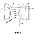
- the pair of band attachment portions 8 are arranged on the watch case 1 at positions of 12 o'clock and 6 o'clock of a dial in the watch case 1. As shown in FIG. 4, a recess 13 is formed at each of the band attachment portions 8 in an edge of the back surface of the watch case 1, and each of a pair of band holding members 10 is engaged in and fixed to the recess 13 of the corresponding one of the band attachment portions 8. The fixation of the band holding member 10 to the recess 13 of the corresponding one of the band attachment portions 8 by a joint pin 9 provided with a spring (See FIG. 2).
- a pin hole 11 through which the joint pin 9 is to be passed is formed in a base end portion of the corresponding band holding member 10, and a pair of connecting holes 12 for receiving the both ends of the corresponding joint pin 9 are formed at both sides of the recess 13 of each of the band attachment portions 8.
- FIGS. 3 and 4 shows a back surface of the band holding member 10.
- the band holding member 10 includes a main body 14 and an engaging portion 15 integrally formed at a base end of the main body 14.
- the engaging portion 15 has an abutting tab 16 designed to abut an edge of the back cover 5 of the watch case 1 as shown in FIG. 2 and a pin hole 11 for receiving the corresponding joint pin 9.
- the engaging portion 15 is engaged in the corresponding recess 13 of the watch case 1 and is fixed to the corresponding band attachment portion 8 of the watch case 1 by the joint pin 9.
- the abutting tab 16 abuts the edge of the back surface of the back cover 5 of the watch case 1, the corresponding band holding member 10 is prevented from freely rotating relative to the watch case 1 and, thus, it is supported to extend in an obliquely and outwardly from the back surface of the watch case 1 in a direction opposite to the front surface thereof.
- a band insertion slot 17 through which the watch band 2 is passed is formed in the main body 14.
- the band insertion slot 17 extends along the extending direction of the main body 14 from a first position which is positioned at or away from the back surface of the watch case 1 in the opposite direction to a second position which is positioned further away from the back surface in the opposite direction than the first position, and is opened at the first and second positions.
- one end of the watch band 2 is inserted firstly into the second or outer opening of the watch band insertion slot 17 of one of the band holding members 10 so that the one end of the watch band 2 is guided at the first or inner opening of the watch band insertion slot 17 by the abutting tab 16 to move along the back surface of the watch case 1 and the one end of the watch band 2 can be introduced easily into the first or inner opening of the watch band insertion slot 17 of the other band holding member 10 to be passed therethrough.
- the watch band 2 when the both end portions of the watch band 2 is wrapped on the user's wrist, the watch band 2 will not apply a large load to the joint pins 9 to detach the joint pins 9 easily and accidentally from the corresponding band attachment portions 8 and then to detach the watch case 1 from the watch band 2. Additionally, the attachment and detachment of the watch band 2 to and from the pair of the band holding members 10, that is of the band attachment portions 8 of the watch case 1, can be easily performed, and the watch band 2, together with the back surfaces of the watch case 1 and the band holding members 10, can be fitted intimately on the user's wrist.
- the band holding members 10 are formed entirely of a soft resin material such as urethane resin so that the band holding members 10 can absorb any external impact applied to the watch case 1.
- the band holding members 10 and the watch band 2 can be colored in any colors to improve an appearance of the wrist watch.
- the both ends of the watch band 2 are provided with detachable fixing means, and, as shown in FIG. 2, in this embodiment a buckle 20 and a band keeper 21 attached at one end of the watch band 2 and punch holes formed at the other end are the fixing means.
- FIG. 5 is a bottom view showing one of the band attachment portions 8 of the watch case 1 of FIG. 4 and one of a pair of band pieces 23 as a watch band which is to be attached to the corresponding one of the band attachment portions 8 without using the band holding members 10 of the first embodiment of the band attachment mechanism.
- the band pieces 23 are well known, a connecting tab 24 is formed at a base end of each of the band pieces 23, and a pin hole 25 is formed in the connecting tab 24.
- the connecting tab 24 is engaged in the recess 13 of the corresponding band attachment portions 8 with the joint pin 9 (see FIG.
- the watch band 2 consisting of one band piece shown in FIG. 2 and the watch band 2 consisting of the pair of band pieces shown in FIG. 5 can be used in accordance with user's choice.
- FIGS. 6 and 7 show a second embodiment of the band attachment mechanism of the invention.
- structural elements of the second embodiment that are the same or similar to those of the first embodiment are denoted by the same reference numerals as those denoting the same or similar structural elements of the first embodiment, and detailed descriptions for them are omitted.
- a slit 25 is formed in a front wall of the main body 14 of each of the band holding members 10 at a position near to the extending end thereof.
- the slit 25 provides a further flexibility to the band holding member 10 so that it may be further curved along the user's wrist to improve the fitness of the band holding member 10, or the watch band, to the user's wrist. Additionally, the slit 25 provides variable design to the watch band, or the wrist watch.
Landscapes
- Physics & Mathematics (AREA)
- General Physics & Mathematics (AREA)
- Electric Clocks (AREA)
- Casings For Electric Apparatus (AREA)
- Professional, Industrial, Or Sporting Protective Garments (AREA)
Abstract
Description
- This invention relates to a watch band attachment mechanism for attaching a watch band to a case of a wrist watch.
- Conventional wrist watches are usually provided with a pair of band attachment portions formed on an outer peripheral surface of the watch case at positions of, for example, 12 o'clock and 6 o'clock of a dial. Each of the band attachment portions includes a pair of supporting projections projecting from the outer peripheral surface of the watch case and a spring rod both ends of which are supported by the supporting projections.
- If the watch band consists of a pair of band pieces, base end portions of the band pieces are attached to the band attachment portions by passing the spring rods of the band attachment portions through connecting holes of the base end portions of the band pieces. If the watch band consists of one band piece at both ends of which connecting holes are formed, the both ends of one band piece are attached to the band attachment portions by passing the spring rods of the band attachment portions through the connecting holes of the both ends of one band piece. There is a case that a watch band consisting of one band piece the both ends of which have no connecting hole is attached to the pair of band attachment portions. When such a one band piece is attached to the pair of band attachment portions of the conventional wrist watch, the one band piece is inserted into a gap between the spring rod of one of the band attachment portions and the outer peripheral surface of the watch case from a front side to a back side of the wrist watch with one end portion of the band piece being positioned at a leading side. Then, the one band piece is pulled along a back surface of the watch case until the one end portion of the one band piece reaches the other band attachment portion, and the one band piece is inserted into a gap between the spring rod of the other band attachment portion and the outer peripheral surface of the watch case from the back side to the front side of the watch case. Thus, the one band piece attached as described above to the pair of band attachment portions of the watch case extends a middle portion thereof along the back surface of the watch case and projects the both end portions thereof to the front side from the back side of the watch case through the band attachment portions.
- Therefore, when the watch band consisting of one band piece having no connecting holes at its both ends is attached to the pair of band attachment portions of the above described conventional wrist watch, the one end portion of the one band piece must be inserted firstly into one of the band attachment portions from the front side to the back side of the watch case, and, then, it must be inserted into the other band attachment portion from the back side to the front side of the watch case. Therefore, the band attachment operation is troublesome. Likewise, a band detachment operation is also troublesome.
- Additionally, when the watch band consisting of one band piece having no connecting holes at the both ends thereof is attached to the pair of band attachment portions of the above described conventional wrist watch and the both end portions of the one band piece are wrapped around a wrist of a user using the wrist watch and are fastened together, the both end portions of the one band piece can not fit on the user's wrist at positions near around the pair of the band attachment portions and the fitness of the both end portions of the one band piece to the user's wrist is not so good because the both end portions of the one band piece are projected from the back side of the watch case to the front side through the pair of band attachment portions.
- Finally, by the above described conventional watch band attachment mechanism, the spring rods of the paired band attachment portions of the wrist watch are subjected to a load directed from the front side toward the back side of the watch case when the both end portions of the one band piece is wrapped around the user's wrist and are fastened together. In this condition, one or both of the spring rods is or are rarely released from the corresponding supporting projections and consequently the watch case is disengaged from the watch band and falls down on a floor or a road.
- In view of the above circumstances, the object of the present invention is to provide a band attachment mechanism by which the band attaching and detaching operations of the watch band, the watch band consisting of the one band piece having no connecting holes at the both ends thereof, to the pair of band attachment portions of the wrist watch becomes easy, possibility of detaching of the watch band from the paired band attachment portions becomes actually zero, and fitness of the watch band on the user's wrist is improved.
- In order to achieve the above object, a watch band attachment mechanism according to the present invention, comprising: a watch case provided with a pair of band attachment portions on an outer peripheral surface thereof; and a pair of band holding members detachably attached to the band attachment portions, each extending from a back surface of the watch case in a direction opposite to a front surface of the watch case, and each having a watch band insertion slot extending from a first position which is positioned at or away from the back surface of the watch case in the opposite direction, to a second position which is positioned further away from the back surface of the watch case in the opposite direction than the first position, the watch band insertion slot opened at the first and second positions, wherein both end portions of a watch band consisting of one band piece are inserted into the band insertion slots of the band holding members to project the both end portions from the openings of the second positions of the watch band insertion slots of the band holding members toward out sides of the band holding members and to extend along the back surface of the watch case between the openings of the first positions of the watch band insertion slots of the band holding members while the band holding members are detachably attached to the band attachment portions of the watch case.
- With the above described arrangement, since the opening of the first position of the watch band insertion slot of each of the pair of band holding members is positioned at or away from the back surface of the watch case in a direction opposite to the front surface of the watch case, and the opening of the second position of the watch band insertion slot of each of the band holding members is positioned further away from the back surface of the watch case in the opposite direction than the first opening, the both end portions of the watch band are lead by the corresponding watch band insertion slots to be extended from the fist openings to the second openings respectively. Thus, the whole of the both end portions of the watch band can fit intimately on the user's wrist even at the pair of the band attachment portions when the both end portions of the watch band are wrapped around the user's wrist and are fixed together.
- Additionally, if each of the band attachment portions on the outer peripheral surface of the watch case is structured as the above described conventional one, the load applied to each of the spring rods of the band attachment portions of the wrist watch by the both end portions of the one band piece of the watch band and directed from the front side toward the back side of the watch case when the both end portions of the one band piece are wrapped around the user's wrist and are fixed together, is reduced by the band holding members so that the possibility of accidental detaching of one or both of the spring rods from the corresponding supporting projections becomes actually zero and consequently disengagement of the watch case from the watch band to allow the wrist watch to fall down on the floor or the road also actually becomes zero.
- Finally, if each of the band attachment portions on the outer peripheral surface of the watch case is structured as the above described conventional one, the band holding members can be attached on and detached from the corresponding band attachment portions easily by the spring rods. And, since each of the watch band insertion slots of the band holding members extends from the first portion to the second position, the both end portions of the watch band can be inserted into the corresponding band insertion slots easily, the watch band consisting of one band piece. Therefore, the attachment and detachment operations of the watch band of the one band piece on and from the pair of the band attachment portions of the watch case can be performed easily.
- This invention can be more fully understood from the following detailed description when taken in conjunction with the accompanying drawings, in which:
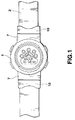
- FIG. 1 is a plan view showing a wrist watch provided with a first embodiment of a band attachment mechanism according to the invention and a watch band consisting of one band piece and attached on the wrist watch by the band attachment mechanism;
- FIG. 2 is a side view of the wrist watch provided with the first embodiment of the band attachment mechanism of FIG. 1, a main portion of the wrist watch being cut-away;
- FIG. 3 is a perspective view showing a back surface of one of band holding members of the first embodiment of the band attachment mechanism of FIG. 1;
- FIG. 4 is a bottom view showing one of the band holding members of the first embodiment of the band attachment mechanism of FIG. 1 and one of band attachment portions of the wrist watch to which the band holding member is to be attached;
- FIG. 5 is a bottom view showing one of the band attachment portions of the watch case of FIG. 4 and one of a pair of band pieces as a watch band which is to be attached to the corresponding one of the band attachment portions without using the band holding members of the first embodiment of the band attachment mechanism;
- FIG. 6 is a plan view showing a wrist watch provided with a second embodiment of the band attachment mechanism according to the invention and a watch band consisting of one band piece and attached on the wrist watch by the band attachment mechanism; and
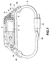
- FIG. 7 is a side view of the wrist watch provided with the second embodiment of the band attachment mechanism of FIG. 6, a main portion of the wrist watch being cut-away.
- FIGS. 1 through 5 show a first embodiment of the invention. Referring to FIG. 1, the first embodiment comprises a
watch case 1 of a wrist watch being provided with a pair of band attachment portions on an outer peripheral surface of the watch case, a pair ofband holding members 10 detachably attached to the band attachment portions of thewatch case 1 and awatch band 2 of one band piece detachably held by theband holding members 10. As shown in FIG. 2, thewatch case 1 houses awatch module 3, a front side thereof is provided with awatch glass 4 and a back side thereof is provided with aback cover 5. Thewatch case 1 is structured by a resin-madeinner case 6 and a resin-madeouter case 7 covering theinner case 6. In this embodiment, theinner case 6 is formed of a hard resin material such as ABS and theouter case 7 is formed of a soft resin material such as urethane resin. Theouter case 7 formed of a soft resin material can absorb any external impact applied to thewatch case 1 to protect thewatch module 3 from the impact. - The pair of
band attachment portions 8 are arranged on thewatch case 1 at positions of 12 o'clock and 6 o'clock of a dial in thewatch case 1. As shown in FIG. 4, arecess 13 is formed at each of theband attachment portions 8 in an edge of the back surface of thewatch case 1, and each of a pair ofband holding members 10 is engaged in and fixed to therecess 13 of the corresponding one of theband attachment portions 8. The fixation of theband holding member 10 to therecess 13 of the corresponding one of theband attachment portions 8 by ajoint pin 9 provided with a spring (See FIG. 2). For the fixation, apin hole 11 through which thejoint pin 9 is to be passed is formed in a base end portion of the correspondingband holding member 10, and a pair of connectingholes 12 for receiving the both ends of thecorresponding joint pin 9 are formed at both sides of therecess 13 of each of theband attachment portions 8. - FIGS. 3 and 4 shows a back surface of the
band holding member 10. Theband holding member 10 includes amain body 14 and anengaging portion 15 integrally formed at a base end of themain body 14. Theengaging portion 15 has anabutting tab 16 designed to abut an edge of theback cover 5 of thewatch case 1 as shown in FIG. 2 and apin hole 11 for receiving thecorresponding joint pin 9. Theengaging portion 15 is engaged in thecorresponding recess 13 of thewatch case 1 and is fixed to the correspondingband attachment portion 8 of thewatch case 1 by thejoint pin 9. - Since the
abutting tab 16 abuts the edge of the back surface of theback cover 5 of thewatch case 1, the correspondingband holding member 10 is prevented from freely rotating relative to thewatch case 1 and, thus, it is supported to extend in an obliquely and outwardly from the back surface of thewatch case 1 in a direction opposite to the front surface thereof. - Since whole of the
band holding member 10 extends obliquely and outwardly from the back surface of thewatch case 1 in the above described direction, the back surfaces of theband holding members 10, together with that of thewatch case 1, intimately fit on a user's wrist so that fitness of the wrist watch to the user's wrist is improved. - A
band insertion slot 17 through which thewatch band 2 is passed is formed in themain body 14. Theband insertion slot 17 extends along the extending direction of themain body 14 from a first position which is positioned at or away from the back surface of thewatch case 1 in the opposite direction to a second position which is positioned further away from the back surface in the opposite direction than the first position, and is opened at the first and second positions. To attach thewatch band 2 consisting of one band piece and having no connecting hole at both ends thereof to the pair ofband attachment portions 8 of thewatch case 1, one end of thewatch band 2 is inserted firstly into the second or outer opening of the watchband insertion slot 17 of one of theband holding members 10 so that the one end of thewatch band 2 is guided at the first or inner opening of the watchband insertion slot 17 by theabutting tab 16 to move along the back surface of thewatch case 1 and the one end of thewatch band 2 can be introduced easily into the first or inner opening of the watchband insertion slot 17 of the otherband holding member 10 to be passed therethrough. With such a structure, when the both end portions of thewatch band 2 is wrapped on the user's wrist, thewatch band 2 will not apply a large load to thejoint pins 9 to detach thejoint pins 9 easily and accidentally from the correspondingband attachment portions 8 and then to detach thewatch case 1 from thewatch band 2. Additionally, the attachment and detachment of thewatch band 2 to and from the pair of theband holding members 10, that is of theband attachment portions 8 of thewatch case 1, can be easily performed, and thewatch band 2, together with the back surfaces of thewatch case 1 and theband holding members 10, can be fitted intimately on the user's wrist. - In this embodiment, the
band holding members 10 are formed entirely of a soft resin material such as urethane resin so that theband holding members 10 can absorb any external impact applied to thewatch case 1. Theband holding members 10 and thewatch band 2 can be colored in any colors to improve an appearance of the wrist watch. - The both ends of the
watch band 2 are provided with detachable fixing means, and, as shown in FIG. 2, in this embodiment abuckle 20 and aband keeper 21 attached at one end of thewatch band 2 and punch holes formed at the other end are the fixing means. - FIG. 5 is a bottom view showing one of the
band attachment portions 8 of thewatch case 1 of FIG. 4 and one of a pair ofband pieces 23 as a watch band which is to be attached to the corresponding one of theband attachment portions 8 without using theband holding members 10 of the first embodiment of the band attachment mechanism. Theband pieces 23 are well known, a connectingtab 24 is formed at a base end of each of theband pieces 23, and apin hole 25 is formed in the connectingtab 24. In order to attach the conventional watch band to theband attachment portions 8 of thewatch case 1, the connectingtab 24 is engaged in therecess 13 of the correspondingband attachment portions 8 with the joint pin 9 (see FIG. 4) being received in thepin hole 25, and then the both ends of thejoin pin 9 are inserted into the pair of the connectingholes 12 of thecorresponding recess 13. With this embodiment, thewatch band 2 consisting of one band piece shown in FIG. 2 and thewatch band 2 consisting of the pair of band pieces shown in FIG. 5 can be used in accordance with user's choice. - FIGS. 6 and 7 show a second embodiment of the band attachment mechanism of the invention. In FIGS. 6 and 7, structural elements of the second embodiment that are the same or similar to those of the first embodiment are denoted by the same reference numerals as those denoting the same or similar structural elements of the first embodiment, and detailed descriptions for them are omitted. In this embodiment, a
slit 25 is formed in a front wall of themain body 14 of each of theband holding members 10 at a position near to the extending end thereof. Theslit 25 provides a further flexibility to theband holding member 10 so that it may be further curved along the user's wrist to improve the fitness of theband holding member 10, or the watch band, to the user's wrist. Additionally, theslit 25 provides variable design to the watch band, or the wrist watch.
Claims (7)
- A band attachment mechanism comprising a watch case (1) provided with a pair of band attachment portions (8) on an outer peripheral surface thereof,
and characterized by further comprising
a pair of band holding members (10) detachably attached to the band attachment portions (8), each extending from a back surface of the watch case (1) in a direction opposite to a front surface of the watch case, and each having a watch band insertion slot (17) extending from a first position which is positioned at or away from the back surface of the watch case (1) in the opposite direction, to a second position which is positioned further away from the back surface of the watch case (1) in the opposite direction than the first position, the band insertion slot (17) opened at the first and second positions, wherein both end portions of a watch band (2) consisting of one band piece are inserted into the band insertion slots (17) of the band holding members (10) to project the both end portions from the openings of the second positions of the watch band insertion slots (17) of the band holding-members (10) toward outsides of the band holding members (10) and to extend along the back surface of the watch case (1) between the openings of the first positions of the watch band insertion slots (17) of the band holding members (10) while the band holding members (10) are detachably attached to the band attachment portions (8) of the watch case (1). - A band attachment mechanism according to claim 1, characterized in that the bond holding members (10) are formed of a shock absorbing material.
- A band attachment mechanism according to claim 2, characterized in that the shock absorbing material is synthetic resin.
- A band attachment mechanism according to claim 1, characterized in that the pair of band holding members (10) are attached to the pair of band attachment portions (8) of the watch case (1) to extend obliquely and outwardly from the back surface of the watch case (1).
- A band attachment mechanism according to claim 1, characterized in that each of the pair of band holding members (10) has an abutment tab (16) which abuts the back surface of the watch case (1) while the band holding members (10) are attached to the band attachment portions (8) of the watch case (1).
- A band attachment mechanism according to claim 1, characterized in that an opening (25) is formed in each of the band holding members (10) at a position near to the extending end of each of the band holding members (10).
- A band attachment mechanism according to claim 1, characterized by further comprising a pair of band pieces (23) which are detachably attached to the band attachment portions (8) of the watch case (1) in place of the pair of band holding members (10) and the watch band (2) consisting of one band piece.
Applications Claiming Priority (3)
| Application Number | Priority Date | Filing Date | Title |
|---|---|---|---|
| JP4741795 | 1995-03-07 | ||
| JP7047417A JPH08238116A (en) | 1995-03-07 | 1995-03-07 | Band mounting structure |
| JP47417/95 | 1995-03-07 |
Publications (3)
| Publication Number | Publication Date |
|---|---|
| EP0731395A2 true EP0731395A2 (en) | 1996-09-11 |
| EP0731395A3 EP0731395A3 (en) | 1999-09-01 |
| EP0731395B1 EP0731395B1 (en) | 2006-05-17 |
Family
ID=12774586
Family Applications (1)
| Application Number | Title | Priority Date | Filing Date |
|---|---|---|---|
| EP96103498A Expired - Lifetime EP0731395B1 (en) | 1995-03-07 | 1996-03-06 | Watch band attachment mechanism |
Country Status (6)
| Country | Link |
|---|---|
| US (1) | US5668784A (en) |
| EP (1) | EP0731395B1 (en) |
| JP (1) | JPH08238116A (en) |
| KR (1) | KR0141000B1 (en) |
| CN (1) | CN1111292C (en) |
| DE (1) | DE69636132T2 (en) |
Cited By (8)
| Publication number | Priority date | Publication date | Assignee | Title |
|---|---|---|---|---|
| FR2748373A1 (en) * | 1996-05-10 | 1997-11-14 | Bouveret Gerard | Detachable connection of watch-case to watch-strap |
| EP0945083A4 (en) * | 1997-03-26 | 2000-05-24 | Citizen Watch Co Ltd | Wrist watch |
| FR2811208A1 (en) * | 2000-07-04 | 2002-01-11 | Hovel Chenorhokian | Wrist watch bracelet blocking/attachment mechanism has end prisms and matching bevelled watch end section with bracelet running through gap/blocked. |
| EP2789254A1 (en) * | 2013-04-12 | 2014-10-15 | Montres Jaquet Droz SA | Ergonomic bracelet for watch or jewel |
| CN105901849A (en) * | 2015-02-20 | 2016-08-31 | 斯沃奇股份公司 | Watch with extending watchband |
| WO2017026728A1 (en) | 2015-08-13 | 2017-02-16 | Samsung Electronics Co., Ltd. | Coupling member and electronic device including the same |
| EP3335080A4 (en) * | 2015-08-13 | 2018-09-05 | Samsung Electronics Co., Ltd. | Coupling member and electronic device including the same |
| EP3918945A1 (en) | 2020-06-05 | 2021-12-08 | Richemont International S.A. | Watch strap and device for attaching such a strap |
Families Citing this family (26)
| Publication number | Priority date | Publication date | Assignee | Title |
|---|---|---|---|---|
| JP2003052422A (en) * | 2001-08-20 | 2003-02-25 | Seiko Instruments Inc | Case, watchband and watch |
| US7303576B2 (en) * | 2004-12-15 | 2007-12-04 | Paul Peters | Vein stabilizer |
| US7628530B2 (en) * | 2007-03-14 | 2009-12-08 | Nike, Inc. | Watch casing construction incorporating watch band lugs |
| US20080310260A1 (en) | 2007-06-07 | 2008-12-18 | Ofer Segal | Modular watch and device for securing a watch strap to a watch casing |
| JP5397286B2 (en) * | 2010-03-23 | 2014-01-22 | カシオ計算機株式会社 | Watches |
| USD672265S1 (en) * | 2012-07-06 | 2012-12-11 | Brett Pulli | Adaptor for receiving the head of a watch |
| JP6400669B2 (en) | 2013-03-15 | 2018-10-03 | アップル インコーポレイテッドApple Inc. | Mounting device and related methods of use and manufacturing |
| JP6020970B2 (en) * | 2013-08-20 | 2016-11-02 | カシオ計算機株式会社 | Watches |
| CH708815B1 (en) * | 2013-11-06 | 2017-12-29 | The Swatch Group Man Services Ag | Cladding element for a middle part of a wristwatch. |
| WO2015107523A1 (en) * | 2014-01-16 | 2015-07-23 | Eran Reuveni | A watch band |
| KR102201921B1 (en) * | 2014-04-11 | 2021-01-12 | 삼성전자주식회사 | Wearable electronic device with buckle |
| US10016029B2 (en) | 2014-08-09 | 2018-07-10 | Apple Inc. | Attachment systems for electronic devices |
| US10182623B2 (en) | 2014-08-11 | 2019-01-22 | Apple Inc. | Consumer product attachment systems having locking or expansion characteristics |
| US10184506B2 (en) | 2014-08-11 | 2019-01-22 | Apple Inc. | Captive elements of an attachment system |
| US10085523B2 (en) | 2014-08-11 | 2018-10-02 | Apple Inc. | Attachment system for an electronic device |
| US9949537B2 (en) | 2015-03-06 | 2018-04-24 | Apple Inc. | Clasp mechanism for wrist-worn devices |
| US10064460B2 (en) | 2015-09-30 | 2018-09-04 | Apple Inc. | Frictional stabilization of band and securement mechanism |
| US10219591B2 (en) | 2016-03-21 | 2019-03-05 | Apple Inc. | Attachment system for an electronic device |
| US10149518B1 (en) | 2016-08-08 | 2018-12-11 | Apple Inc. | Clasp assembly for a wearable device |
| US10149519B2 (en) * | 2016-11-07 | 2018-12-11 | James Giles | Dual engagement watch strap connector |
| CN107367924B (en) * | 2017-05-27 | 2019-11-22 | 江苏金钿实业有限公司 | A kind of application method of watch bracelet drilling equipment |
| CN109799691B (en) * | 2019-03-31 | 2021-03-16 | 翁琦 | Watch capable of realizing watchband replacement based on track splicing |
| CN111552168A (en) * | 2020-04-22 | 2020-08-18 | 深圳五洲无线股份有限公司 | a watch |
| CN116249462B (en) | 2020-06-16 | 2026-04-14 | 汤姆福特国际有限责任公司 | Single watchband |
| CN113229812A (en) * | 2021-06-15 | 2021-08-10 | 深圳叩鼎科技有限责任公司 | Intelligent watch capable of accurately detecting blood oxygen |
| JP2024126645A (en) * | 2023-03-08 | 2024-09-20 | カシオ計算機株式会社 | Wearable band, wearable device, and method for wearing the wearable band |
Family Cites Families (9)
| Publication number | Priority date | Publication date | Assignee | Title |
|---|---|---|---|---|
| DE1066776B (en) * | 1959-10-08 | Konstanz Karl H. Heinz | Bracelet attachment for wristwatch | |
| GB117331A (en) * | 1917-08-23 | 1918-07-18 | Joseph Arkinstall | Improvements in and relating to Watch Wristlets. |
| GB117061A (en) * | 1918-05-03 | 1918-07-04 | Samuel Simon Speyer | Improvements in or relating to Wristlet-watches. |
| US1849482A (en) * | 1928-04-25 | 1932-03-15 | George P Dike | Wrist watch |
| US1760689A (en) * | 1929-07-30 | 1930-05-27 | Hadley Company Inc | Bracelet for watches or the like |
| US4639144A (en) * | 1982-07-01 | 1987-01-27 | Big Time, Inc. | Novelty wrist watch |
| GB2163038A (en) * | 1984-08-17 | 1986-02-19 | Citizen Watch Co Ltd | Structure for securing a band to a watchcase |
| US5363351A (en) * | 1993-06-29 | 1994-11-08 | Chisco, Inc. | Watchband adaptor fitting for a wristwatch casing |
| US5442602A (en) * | 1993-08-25 | 1995-08-15 | Casio Computer Co., Ltd. | Wristwatch case with shock absorbing members on the rear side thereof |
-
1995
- 1995-03-07 JP JP7047417A patent/JPH08238116A/en active Pending
-
1996
- 1996-03-05 US US08/611,243 patent/US5668784A/en not_active Expired - Lifetime
- 1996-03-06 CN CN96103282A patent/CN1111292C/en not_active Expired - Lifetime
- 1996-03-06 DE DE69636132T patent/DE69636132T2/en not_active Expired - Lifetime
- 1996-03-06 EP EP96103498A patent/EP0731395B1/en not_active Expired - Lifetime
- 1996-03-06 KR KR1019960005859A patent/KR0141000B1/en not_active Expired - Fee Related
Cited By (11)
| Publication number | Priority date | Publication date | Assignee | Title |
|---|---|---|---|---|
| FR2748373A1 (en) * | 1996-05-10 | 1997-11-14 | Bouveret Gerard | Detachable connection of watch-case to watch-strap |
| EP0945083A4 (en) * | 1997-03-26 | 2000-05-24 | Citizen Watch Co Ltd | Wrist watch |
| FR2811208A1 (en) * | 2000-07-04 | 2002-01-11 | Hovel Chenorhokian | Wrist watch bracelet blocking/attachment mechanism has end prisms and matching bevelled watch end section with bracelet running through gap/blocked. |
| EP2789254A1 (en) * | 2013-04-12 | 2014-10-15 | Montres Jaquet Droz SA | Ergonomic bracelet for watch or jewel |
| CN105901849A (en) * | 2015-02-20 | 2016-08-31 | 斯沃奇股份公司 | Watch with extending watchband |
| CN105901849B (en) * | 2015-02-20 | 2018-05-29 | 斯沃奇股份公司 | Wrist-watch with expansion table band |
| WO2017026728A1 (en) | 2015-08-13 | 2017-02-16 | Samsung Electronics Co., Ltd. | Coupling member and electronic device including the same |
| EP3335080A4 (en) * | 2015-08-13 | 2018-09-05 | Samsung Electronics Co., Ltd. | Coupling member and electronic device including the same |
| US10168736B2 (en) | 2015-08-13 | 2019-01-01 | Samsung Electronics Co., Ltd. | Coupling member and electronic device including the same |
| EP3918945A1 (en) | 2020-06-05 | 2021-12-08 | Richemont International S.A. | Watch strap and device for attaching such a strap |
| CH717498A1 (en) * | 2020-06-05 | 2021-12-15 | Richemont Int Sa | Watch strap and attachment device for such a strap. |
Also Published As
| Publication number | Publication date |
|---|---|
| KR960033339A (en) | 1996-10-22 |
| DE69636132T2 (en) | 2006-09-14 |
| EP0731395B1 (en) | 2006-05-17 |
| JPH08238116A (en) | 1996-09-17 |
| DE69636132D1 (en) | 2006-06-22 |
| KR0141000B1 (en) | 1998-07-01 |
| CN1138972A (en) | 1997-01-01 |
| US5668784A (en) | 1997-09-16 |
| EP0731395A3 (en) | 1999-09-01 |
| HK1013447A1 (en) | 1999-08-27 |
| CN1111292C (en) | 2003-06-11 |
Similar Documents
| Publication | Publication Date | Title |
|---|---|---|
| EP0731395B1 (en) | Watch band attachment mechanism | |
| US4217681A (en) | Releasable and adjustable end attachment for watchband and the like | |
| KR100523657B1 (en) | Device for attaching a bracelet to a watchcase | |
| US5244134A (en) | Strap attachment for a wrist instrument | |
| US4712826A (en) | Automotive window and molding assembly having a device for mounting a corner joint | |
| EP0474937A1 (en) | Helmet | |
| US4432476A (en) | Band attachment assembly for attaching a watchband to a watchcase | |
| US3929265A (en) | Watch strap with plastic clip | |
| EP0067524B1 (en) | Fastener for assembling two hollow members | |
| EP0123862B1 (en) | Crash helmet | |
| GB2158145A (en) | Watch band fastener | |
| US4266326A (en) | Watchband connector | |
| CN100370374C (en) | Cases and straps and timepieces | |
| JPH0634769A (en) | End-section connecting structure of band for wrist watch | |
| EP0288663A1 (en) | Glove holder | |
| HK1013447B (en) | Watch band attachment mechanism | |
| KR100288958B1 (en) | Removable Floor Stop Assembly for Slide Fasteners | |
| JP3964492B2 (en) | Watch band mounting structure | |
| GB2129280A (en) | Watchband attachment structure | |
| US5090094A (en) | End connector with integral pivotal clam shell | |
| KR100364049B1 (en) | A buckle for band | |
| CN216255797U (en) | Watchband buckle | |
| KR200193507Y1 (en) | A band for watch | |
| JPH0537766Y2 (en) | ||
| JPH0527048Y2 (en) |
Legal Events
| Date | Code | Title | Description |
|---|---|---|---|
| PUAI | Public reference made under article 153(3) epc to a published international application that has entered the european phase |
Free format text: ORIGINAL CODE: 0009012 |
|
| 17P | Request for examination filed |
Effective date: 19960306 |
|
| AK | Designated contracting states |
Kind code of ref document: A2 Designated state(s): DE FR GB |
|
| RAP1 | Party data changed (applicant data changed or rights of an application transferred) |
Owner name: CASIO COMPUTER CO., LTD. |
|
| PUAL | Search report despatched |
Free format text: ORIGINAL CODE: 0009013 |
|
| AK | Designated contracting states |
Kind code of ref document: A3 Designated state(s): DE FR GB |
|
| 17Q | First examination report despatched |
Effective date: 20041004 |
|
| GRAP | Despatch of communication of intention to grant a patent |
Free format text: ORIGINAL CODE: EPIDOSNIGR1 |
|
| GRAS | Grant fee paid |
Free format text: ORIGINAL CODE: EPIDOSNIGR3 |
|
| GRAA | (expected) grant |
Free format text: ORIGINAL CODE: 0009210 |
|
| AK | Designated contracting states |
Kind code of ref document: B1 Designated state(s): DE FR GB |
|
| REG | Reference to a national code |
Ref country code: GB Ref legal event code: FG4D |
|
| REF | Corresponds to: |
Ref document number: 69636132 Country of ref document: DE Date of ref document: 20060622 Kind code of ref document: P |
|
| REG | Reference to a national code |
Ref country code: HK Ref legal event code: GR Ref document number: 1013447 Country of ref document: HK |
|
| ET | Fr: translation filed | ||
| PLBE | No opposition filed within time limit |
Free format text: ORIGINAL CODE: 0009261 |
|
| STAA | Information on the status of an ep patent application or granted ep patent |
Free format text: STATUS: NO OPPOSITION FILED WITHIN TIME LIMIT |
|
| 26N | No opposition filed |
Effective date: 20070220 |
|
| PGFP | Annual fee paid to national office [announced via postgrant information from national office to epo] |
Ref country code: DE Payment date: 20140328 Year of fee payment: 19 |
|
| PGFP | Annual fee paid to national office [announced via postgrant information from national office to epo] |
Ref country code: FR Payment date: 20140319 Year of fee payment: 19 |
|
| PGFP | Annual fee paid to national office [announced via postgrant information from national office to epo] |
Ref country code: GB Payment date: 20140319 Year of fee payment: 19 |
|
| REG | Reference to a national code |
Ref country code: DE Ref legal event code: R119 Ref document number: 69636132 Country of ref document: DE |
|
| GBPC | Gb: european patent ceased through non-payment of renewal fee |
Effective date: 20150306 |
|
| REG | Reference to a national code |
Ref country code: FR Ref legal event code: ST Effective date: 20151130 |
|
| PG25 | Lapsed in a contracting state [announced via postgrant information from national office to epo] |
Ref country code: DE Free format text: LAPSE BECAUSE OF NON-PAYMENT OF DUE FEES Effective date: 20151001 Ref country code: GB Free format text: LAPSE BECAUSE OF NON-PAYMENT OF DUE FEES Effective date: 20150306 |
|
| PG25 | Lapsed in a contracting state [announced via postgrant information from national office to epo] |
Ref country code: FR Free format text: LAPSE BECAUSE OF NON-PAYMENT OF DUE FEES Effective date: 20150331 |