EP0731336A2 - Method and apparatus for measuring the dynamic camber of vehicle tyres - Google Patents
Method and apparatus for measuring the dynamic camber of vehicle tyres Download PDFInfo
- Publication number
- EP0731336A2 EP0731336A2 EP96102952A EP96102952A EP0731336A2 EP 0731336 A2 EP0731336 A2 EP 0731336A2 EP 96102952 A EP96102952 A EP 96102952A EP 96102952 A EP96102952 A EP 96102952A EP 0731336 A2 EP0731336 A2 EP 0731336A2
- Authority
- EP
- European Patent Office
- Prior art keywords
- tire
- road surface
- camber
- vehicle
- energy
- Prior art date
- Legal status (The legal status is an assumption and is not a legal conclusion. Google has not performed a legal analysis and makes no representation as to the accuracy of the status listed.)
- Granted
Links
Images

Classifications
-
- G—PHYSICS
- G01—MEASURING; TESTING
- G01B—MEASURING LENGTH, THICKNESS OR SIMILAR LINEAR DIMENSIONS; MEASURING ANGLES; MEASURING AREAS; MEASURING IRREGULARITIES OF SURFACES OR CONTOURS
- G01B11/00—Measuring arrangements characterised by the use of optical techniques
- G01B11/26—Measuring arrangements characterised by the use of optical techniques for measuring angles or tapers; for testing the alignment of axes
- G01B11/275—Measuring arrangements characterised by the use of optical techniques for measuring angles or tapers; for testing the alignment of axes for testing wheel alignment
-
- B—PERFORMING OPERATIONS; TRANSPORTING
- B60—VEHICLES IN GENERAL
- B60G—VEHICLE SUSPENSION ARRANGEMENTS
- B60G2200/00—Indexing codes relating to suspension types
- B60G2200/40—Indexing codes relating to the wheels in the suspensions
- B60G2200/46—Indexing codes relating to the wheels in the suspensions camber angle
-
- B—PERFORMING OPERATIONS; TRANSPORTING
- B60—VEHICLES IN GENERAL
- B60G—VEHICLE SUSPENSION ARRANGEMENTS
- B60G2204/00—Indexing codes related to suspensions per se or to auxiliary parts
- B60G2204/10—Mounting of suspension elements
- B60G2204/11—Mounting of sensors thereon
-
- B—PERFORMING OPERATIONS; TRANSPORTING
- B60—VEHICLES IN GENERAL
- B60G—VEHICLE SUSPENSION ARRANGEMENTS
- B60G2204/00—Indexing codes related to suspensions per se or to auxiliary parts
- B60G2204/10—Mounting of suspension elements
- B60G2204/11—Mounting of sensors thereon
- B60G2204/113—Tyre related sensors
-
- B—PERFORMING OPERATIONS; TRANSPORTING
- B60—VEHICLES IN GENERAL
- B60G—VEHICLE SUSPENSION ARRANGEMENTS
- B60G2401/00—Indexing codes relating to the type of sensors based on the principle of their operation
- B60G2401/21—Laser
-
- B—PERFORMING OPERATIONS; TRANSPORTING
- B60—VEHICLES IN GENERAL
- B60G—VEHICLE SUSPENSION ARRANGEMENTS
- B60G2600/00—Indexing codes relating to particular elements, systems or processes used on suspension systems or suspension control systems
- B60G2600/04—Means for informing, instructing or displaying
- B60G2600/042—Monitoring means
-
- G—PHYSICS
- G01—MEASURING; TESTING
- G01B—MEASURING LENGTH, THICKNESS OR SIMILAR LINEAR DIMENSIONS; MEASURING ANGLES; MEASURING AREAS; MEASURING IRREGULARITIES OF SURFACES OR CONTOURS
- G01B2210/00—Aspects not specifically covered by any group under G01B, e.g. of wheel alignment, caliper-like sensors
- G01B2210/10—Wheel alignment
- G01B2210/20—Vehicle in a state of translatory motion
-
- G—PHYSICS
- G01—MEASURING; TESTING
- G01B—MEASURING LENGTH, THICKNESS OR SIMILAR LINEAR DIMENSIONS; MEASURING ANGLES; MEASURING AREAS; MEASURING IRREGULARITIES OF SURFACES OR CONTOURS
- G01B2210/00—Aspects not specifically covered by any group under G01B, e.g. of wheel alignment, caliper-like sensors
- G01B2210/10—Wheel alignment
- G01B2210/26—Algorithms, instructions, databases, computerized methods and graphical user interfaces employed by a user in conjunction with the wheel aligner
-
- G—PHYSICS
- G01—MEASURING; TESTING
- G01B—MEASURING LENGTH, THICKNESS OR SIMILAR LINEAR DIMENSIONS; MEASURING ANGLES; MEASURING AREAS; MEASURING IRREGULARITIES OF SURFACES OR CONTOURS
- G01B2210/00—Aspects not specifically covered by any group under G01B, e.g. of wheel alignment, caliper-like sensors
- G01B2210/10—Wheel alignment
- G01B2210/28—Beam projector and related sensors, camera, inclinometer or other active sensing or projecting device
Definitions
- the invention relates to an apparatus and to a method for determining the dynamic camber of vehicle tires. More particularly, the invention relates to such an apparatus and method which measure the dynamic camber on a vehicle tire in an actual operating road environment, wherein changes in road surface and inclination affect the camber. Even more particularly, the invention relates to such an apparatus and method in which the camber angles measured throughout a particular road surface are stored in a computer and reused at a test facility for testing other tires in a controlled environment while impressing on the subsequent test tires actual cambers which the tires would experience under actual road operating conditions and when used with a particular vehicle.
- camber on a tire and its effect on the wear and ride characteristics thereof is only one of a number of tests performed on tires to ensure that the tire performs satisfactorily, and in particular, that the tire performs satisfactorily on specific vehicles.
- U. S. Patent No. 4,898,464 discloses a method and apparatus for determining the position of an object so that the steerable wheels of the vehicle may be aligned.
- the mechanism includes a microcomputer, a laser, mirror and phototransistor laser ray.
- the laser light is both emitted and received to provide the information needed to align the steerable wheels of the vehicle.
- U. S. Patent No. 2,077,082 discloses a device that measures both the camber and caster in wheel mechanisms.
- the measuring device is installed on a shaft of a spindle to allow the camber and caster readings to be taken with the vehicle resting on the floor.
- the weight distribution for the vehicle will go up upon all the wheels, attempting to simulate actual road conditions.
- U. S. Patent No. 3,963,352 discloses a wheel alignment apparatus wherein a sensor unit is provided which includes a casing, mirror and magnet. The sensor unit is secured to the axle housing of the wheel by use of the magnet. The sensing unit includes a light source and light-sensitive devices. The light is directed to and reflected back from the mirror to provide the measurement necessary to determine the caster and camber of the wheels.
- U. S. Patent No. 4,578,870 discloses a selectable beam/plane-projecting laser and alignment system for a vehicle body and frame.
- a laser is attached to the vehicle through a carrier bar, and a switching mechanism has a holder member and slide member that is utilized to alternate between a beam of light or plane of light.
- the plane of light may be projected in any direction orthogonal to the mounting bars.
- U. S. Patent No. 4,454,659 discloses an adjustable carriage assembly utilized in a body alignment device.
- the adjustable carriage assembly is provided with a measurement bar which is secured to the vehicle, and has a laser sighting instrument attached thereto.
- Objectives of the invention include providing a unique apparatus which is of a relatively lightweight and inexpensive construction, and which may be readily mounted on a test vehicle at a vehicle test site for measuring, obtaining and storing data collected of the angles of camber applied to the tire as the tire moves along an actual road surface under actual driving conditions.
- a further objective of the invention is to provide such an apparatus and method wherein a pair of lasers or other type transducers are mounted on a bracket which extends perpendicularly outwardly from a non-rotating hub mounted on the actual vehicle tire/wheel assembly; and in which associated equipment instantaneously measures the distance of the lasers from the ground, from which can be calculated the camber angles on the tire as the tire moves along an actual road surface.
- Another objective of the invention is to provide such an apparatus and method which converts detected analog signals into digital signals which are stored in a computer or other memory device along with other measured data including time, tire revolutions, forces and moments, which computer will be on-board the vehicle as it moves along the road surface, and which stored information then is applied to tire test equipment at a remote facility, subjecting later developed tires to the same camber angles to which the initial test tire experienced in order to develop the most satisfactory tire for use on the particular vehicle on which the initial tire was tested at a test track.
- a still further objective of the invention is to provide such a method and apparatus which measures the angle between the tire/wheel plane and the plane of the road surface directly below the tire in order to provide a meaningful measurement for characterizing the real world environment in which a tire must operate, and which measures the vehicle camber, dynamic camber changes, as well as tilt in the road surfaces, to completely capture a tire's operating camber angles with respect to an actual road surface, thereby measuring the true camber angles that a tire experiences in a working environment.
- Another objective of the invention is to provide such an apparatus and method which is considerably simpler and lower cost than prior art camber measurement apparatus and methods, and which is easily and rapidly installed on a test vehicle which then can be driven, even on public roads, in order to quantify the distribution of the camber angles for a particular vehicle/tire/driver/road course system.
- the apparatus of the present invention for measuring the dynamic angles of camber of a tire of a moving vehicle, wherein said apparatus includes a bracket; non-rotating hub means for mounting the bracket on a hub of a tire/wheel assembly of the vehicle, said bracket adapted to extend outwardly from the tire/wheel assembly above a road surface; a pair of transducers mounted in a predetermined spaced relationship on the bracket above the road surface for directing beams of energy against the road surface; detector means for detecting the magnitude of energy reflected off the road surface from the beams of energy, said detector means producing signals, the magnitudes of which represent the distances between the transducers and the road surface at a specific instance of time; signal processing means coupled with the detector means for receiving the signals from the detector means and converting said signals into output data representing the angles of camber of the tire for specific instances of time; and memory means for storing the output data.
- the method of the present invention for measuring the dynamic camber of vehicle tires, wherein said method includes the steps of providing at least a pair of energy sources for producing beams of energy; providing detector means for each of said energy sources; mounting said energy sources and detector means on a wheel assembly of the vehicle at a predetermined position above the road surface and at a predetermined spaced relationship with respect to each other; directing an energy beam from each energy source against the road surface; detecting and measuring the reflected energy of each energy beam from the road surface by a detector means as the vehicle moves along the road surface; converting the detected and measured reflected energy into signals; processing the signals in a signal processor to determine the distances of the detectors from the road surface; calculating the angle of camber which the tire experiences at any particular instant of time based on the calculated distances; and storing the calculated angle of camber at a particular instant of time in a memory device.
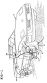
- FIG. 1 is a diagrammatic perspective view showing a usual motor vehicle 1 having a tire/wheel assembly 2 mounted thereon, which consists of a wheel 3 and a tire 4.
- the apparatus of the present invention for measuring the dynamic angles of camber of tire/wheel assembly 2 is shown mounted thereon, and is indicated generally at 5.
- Apparatus 5 is mounted on a non-rotating hub assembly, indicated generally at 6, which is mounted on rotating wheel 3 of tire/wheel assembly 2.
- Hub assembly 6 is a commercially available device presently being used for performing various load tests on vehicle tires. These devices are referred to as load cell assemblies, and may consist of an adapter hub, transducer and slip ring assembly, which is mounted on wheel 3, and which may contain various internal load cells 7 and associated amplifiers for determining various forces exerted on the tire/wheel assembly.
- load cell assemblies may consist of an adapter hub, transducer and slip ring assembly, which is mounted on wheel 3, and which may contain various internal load cells 7 and associated amplifiers for determining various forces exerted on the tire/wheel assembly.
- One example of a non-rotating hub assembly 6 which may be used with the apparatus of the present invention is a Model 242 Transducer Interface Assembly manufactured and distributed by GSE, Inc. of Farmington Hills, Michigan.
- GSE GSE, Inc. of Farmington Hills, Michigan.
- other types of non-rotating hub assemblies can be utilized for mounting of apparatus 5 on the tire/wheel assembly 2 and for carrying out the method steps of the present invention without affecting the concept thereof.
- Apparatus 5 includes a bracket 10 (FIG. 2), having an angular leg 11, a horizontal lower cross member 12, a pair of vertical legs 13 and 14, and an upper horizontal leg 15. Bracket 10 is mounted by a plate 16 to hub assembly 6 and extends in a horizontal cantilever fashion therefrom.
- the particular construction of bracket 10 can vary from that shown in the drawings and described above without affecting the concept of the invention.
- transducers 19 and 20 are mounted on bracket 10, preferably at the junction of legs 13 and 14 with lower cross member 12.
- transducers 19 and 20 are laser units, each of which includes an emitter 25 for emitting beams of energy, indicated at 23 and 23a, respectively, and a sensor 26 for detecting the reflected beams 24 and 24a, respectively.
- the particular type of laser units 19 and 20 may vary, but preferably are relatively high speed in order to obtain the desired results.
- One type of laser unit found suitable for the present invention is a Model LB-70/LB-11 or LB-72/LB-12 being sold and distributed by Keyence Corporation of America.
- This particular laser unit preferably is mounted with a standoff distance of 100 mm (indicated at 28 in FIG. 2), and will have a measurement range of ⁇ 40 mm.
- the laser is a semiconductor laser having a wave length of 780 nm, 3mW, Class IIIb pulse duration: 70 ⁇ . It will have a spot diameter at the 100 mm distance of 1.0 x 2.0 mm, and a linearity of 1.6% of the measurement range of 80 mm.
- laser units can be used without affecting the concept of the invention.
- other types of transducers for producing various beams of energy such as sonic devices, infrared devices, or the like, could also be utilized, and the invention need not be limited to laser units, as described in the preferred embodiment.
- laser units such as described above have been found to be the most satisfactory to date for accomplishing the desired results.
- a non-rotating hub assembly 6 may be mounted on both the front and rear tire/wheel assemblies 2 and are connected by a stabilizing beam 8, with the test apparatus 5 of the present invention being shown mounted only on the front tire/wheel assembly.
- the reflected energy beams 24 and 24a are detected and measured by sensors 26, usually in a DC voltage, which is fed through control cables 31 and 32 to a computer 34 located within the vehicle.
- Computer 34 also may be connected through other electric cables 35 and 36 to the strain gauges or load cells 7 of hub assemblies 6 mounted on the front and rear tire wheel assemblies for gathering additional tire test data. Readily available software easily converts the DC analog voltage signals supplied by the sensors into digital signals or data which is then stored in the memory of computer 34.
- bracket 11 tilting with respect to its normal horizontal position which is represented by horizontal line 37, providing two different vertical distances 28a and 28b between laser units 19 and 20, respectively, and the road surface 38.
- These differences in distance will affect the positions of the reflected energy beams 24 and 24a measured by sensors 26 and 26a, providing different detected DC voltages which are transmitted to the computer through cables 31 and 32 and converted into the stored data, usually in digital form.
- the computer by simple mathematical calculations, can determine distance to the road surface and the angle of camber exerted on tire 4 at any instant in time, as indicated at 44 in FIG. 2A.
- the DC voltage readings represent the distances of the lasers from road surface 38 at any instant of time.
- the distance to the road surface as a function of distance travelled is saved in the computer memory. Since the horizontal separation, indicated at 39, between the two spaced lasers and, correspondingly, between the two sensors, is known, simple calculations will determine the angle of cross members 12 and 15 which are perpendicular to the vertical plane 45 of tire 4, and, correspondingly, the angle of camber of tire 4. Again, anyone skilled in the art can use standard software, or easily derive the angle of camber, upon knowing the vertical distances between the two laser beams and the road surface, and the horizontal separation therebetween, which in the preferred embodiment is approximately 13 inches.
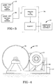
- Tire test equipment 40 includes a load or road wheel 41 which is rotated at various speeds, and is in engagement with a test tire 42.
- Tire 42 is mounted on various control devices 43 for moving tire 42 against road wheel 41 with various applied loads and moments, including various camber angles.
- the stored data of computer 34 which includes instantaneously recorded times, tire revolutions, force and moment measurements as well as camber angle measurements, is fed into the appropriate control panel, computer or other mechanism, indicated at 47, for supplying the commands to the control system for continuously adjusting the angles of camber between test tire 42 and road wheel 41 in the same manner as the previously tested tire 4 experienced as it moved along actual road surface 38.
- various test tires 42 can be placed on test equipment 40 and the same dynamic conditions, including dynamic angles of camber, which the actually tested tire 4 experienced, will be experienced on tires 42, exactly as if the test tire 42 had been driven along the same course by the same driver on the same vehicle as was tire 4.
- this stored data of actual dynamic camber angles enables the tire designers to continually redesign certain features of the tire in order to provide a final production tire which provides the best wear and ride characteristics by using actually measured dynamic camber angles, which is a significant improvement over the camber angles determined by the prior art laboratory test methods.
- This can be determined by tire test equipment 40 in a conveniently located laboratory and in a controlled environment, but provides results as if the tire were tested on the actual vehicle 1, on which the final production tire is intended for use, without the expensive, time-consuming procedure of going to a vehicle test site and mounting the various test tires on the actual vehicle.
- the method of the present invention is shown in generally block diagram form in FIG. 3, in which the two laser units, each having an emitter and sensor, provide the analog signals to computer 34, which will convert the analog signals to digital signals and store the same in the memory, which is then used with the laboratory tire test equipment 40 repeatedly for performing numerous tests on additional test tires 42.
- computer 34 which will convert the analog signals to digital signals and store the same in the memory, which is then used with the laboratory tire test equipment 40 repeatedly for performing numerous tests on additional test tires 42.
- the method and apparatus for measuring the dynamic camber of vehicle tires is simplified, provides an effective, safe, inexpensive, and efficient method and apparatus which achieves all the enumerated objectives, provides for eliminating difficulties encountered with prior methods and apparatus, and solves problems and obtains new results in the art.
Landscapes
- Physics & Mathematics (AREA)
- General Physics & Mathematics (AREA)
- Length Measuring Devices By Optical Means (AREA)
- Length Measuring Devices With Unspecified Measuring Means (AREA)
- Body Structure For Vehicles (AREA)
Abstract
Description
- The invention relates to an apparatus and to a method for determining the dynamic camber of vehicle tires. More particularly, the invention relates to such an apparatus and method which measure the dynamic camber on a vehicle tire in an actual operating road environment, wherein changes in road surface and inclination affect the camber. Even more particularly, the invention relates to such an apparatus and method in which the camber angles measured throughout a particular road surface are stored in a computer and reused at a test facility for testing other tires in a controlled environment while impressing on the subsequent test tires actual cambers which the tires would experience under actual road operating conditions and when used with a particular vehicle.
- Various complicated, bulky and expensive equipment has been developed for statically measuring camber on a tire, which is one of the factors tested to determine tire wear and ride characteristics. These prior art systems and equipment are expensive and difficult to operate for performing repeated tests on numerous tires in order to gather sufficient data for determining the effects of camber on a particular tire.
- The measurement of camber on a tire and its effect on the wear and ride characteristics thereof, is only one of a number of tests performed on tires to ensure that the tire performs satisfactorily, and in particular, that the tire performs satisfactorily on specific vehicles.
- The trend in the tire and automobile industry today is to closely match and design a particular tire as original equipment for a particular vehicle. Thus, automobile manufacturers, in selling the vehicle, will have mounted thereon a particular tire which has been found to provide the most desirable wear and ride characteristics for that particular vehicle and tire.
- In order to ensure that the tire provided for a particular vehicle provides the desired results, various tests are performed on prototypes of such tires on the actual vehicle. However, it is difficult for a tire manufacturer to obtain the actual vehicle intended for future production for a sufficient length of time in order to perform all of the tests desired and then repeat the tests on various tires and modifications thereto, in order to arrive at the optimum tire design. The automobile manufacturers usually permit the tire manufacturers to use one of its prototype vehicles for a relatively short period of time and at a facility remote from the tire manufacturer's laboratory to test its prototype tire intended for use on that vehicle when it becomes a future production model.
- Heretofore, the effect of camber on a vehicle tire was obtained in a laboratory tire test facility, wherein a road or load wheel is engaged with a test tire and the angle of inclination or camber of the test tire with the road wheel is varied during test cycles. However, such a test does not provide for a real-world environment, nor account for the effect that the structure of a particular vehicle, such as its suspension system, weight and driving characteristics, have on the camber angle which is impressed upon the tire, which then affects the wear characteristics of the tire.
- Various prior art devices, some of which use lasers, have been utilized for alignment and for statically measuring both camber and caster in wheel mechanisms, as shown in the following patents.
- U. S. Patent No. 4,898,464 discloses a method and apparatus for determining the position of an object so that the steerable wheels of the vehicle may be aligned. The mechanism includes a microcomputer, a laser, mirror and phototransistor laser ray. The laser light is both emitted and received to provide the information needed to align the steerable wheels of the vehicle.
- U. S. Patent No. 2,077,082 discloses a device that measures both the camber and caster in wheel mechanisms. The measuring device is installed on a shaft of a spindle to allow the camber and caster readings to be taken with the vehicle resting on the floor. The weight distribution for the vehicle will go up upon all the wheels, attempting to simulate actual road conditions.
- U. S. Patent No. 3,963,352 discloses a wheel alignment apparatus wherein a sensor unit is provided which includes a casing, mirror and magnet. The sensor unit is secured to the axle housing of the wheel by use of the magnet. The sensing unit includes a light source and light-sensitive devices. The light is directed to and reflected back from the mirror to provide the measurement necessary to determine the caster and camber of the wheels.
- U. S. Patent No. 4,578,870 discloses a selectable beam/plane-projecting laser and alignment system for a vehicle body and frame. A laser is attached to the vehicle through a carrier bar, and a switching mechanism has a holder member and slide member that is utilized to alternate between a beam of light or plane of light. The plane of light may be projected in any direction orthogonal to the mounting bars.
- U. S. Patent No. 4,454,659 discloses an adjustable carriage assembly utilized in a body alignment device. The adjustable carriage assembly is provided with a measurement bar which is secured to the vehicle, and has a laser sighting instrument attached thereto.
- Although certain of these prior art alignment systems use lasers to enable the camber of the vehicle tires to be determined, none of these prior art patents, nor other known prior art devices, provide a device which is attached to a moving vehicle in order to obtain the dynamic angles of camber which the tire experiences as it moves along an actual road surface on a particular moving vehicle.
- Therefore, the need exists for an improved apparatus and method for determination of the dynamic camber on a vehicle tire, performed while the tire is moving along an actual road surface and mounted on an actual vehicle of the type on which the tire will be used, which data can then be used at a tire test facility on other test tires in order to test various modifications and changes to a tire in order to arrive at the optimum tire design for a particular vehicle.
- Objectives of the invention include providing a unique apparatus which is of a relatively lightweight and inexpensive construction, and which may be readily mounted on a test vehicle at a vehicle test site for measuring, obtaining and storing data collected of the angles of camber applied to the tire as the tire moves along an actual road surface under actual driving conditions.
- A further objective of the invention is to provide such an apparatus and method wherein a pair of lasers or other type transducers are mounted on a bracket which extends perpendicularly outwardly from a non-rotating hub mounted on the actual vehicle tire/wheel assembly; and in which associated equipment instantaneously measures the distance of the lasers from the ground, from which can be calculated the camber angles on the tire as the tire moves along an actual road surface.
- Another objective of the invention is to provide such an apparatus and method which converts detected analog signals into digital signals which are stored in a computer or other memory device along with other measured data including time, tire revolutions, forces and moments, which computer will be on-board the vehicle as it moves along the road surface, and which stored information then is applied to tire test equipment at a remote facility, subjecting later developed tires to the same camber angles to which the initial test tire experienced in order to develop the most satisfactory tire for use on the particular vehicle on which the initial tire was tested at a test track.
- A still further objective of the invention is to provide such a method and apparatus which measures the angle between the tire/wheel plane and the plane of the road surface directly below the tire in order to provide a meaningful measurement for characterizing the real world environment in which a tire must operate, and which measures the vehicle camber, dynamic camber changes, as well as tilt in the road surfaces, to completely capture a tire's operating camber angles with respect to an actual road surface, thereby measuring the true camber angles that a tire experiences in a working environment.
- Another objective of the invention is to provide such an apparatus and method which is considerably simpler and lower cost than prior art camber measurement apparatus and methods, and which is easily and rapidly installed on a test vehicle which then can be driven, even on public roads, in order to quantify the distribution of the camber angles for a particular vehicle/tire/driver/road course system.
- These objectives and advantages are obtained by the apparatus of the present invention for measuring the dynamic angles of camber of a tire of a moving vehicle, wherein said apparatus includes a bracket; non-rotating hub means for mounting the bracket on a hub of a tire/wheel assembly of the vehicle, said bracket adapted to extend outwardly from the tire/wheel assembly above a road surface; a pair of transducers mounted in a predetermined spaced relationship on the bracket above the road surface for directing beams of energy against the road surface; detector means for detecting the magnitude of energy reflected off the road surface from the beams of energy, said detector means producing signals, the magnitudes of which represent the distances between the transducers and the road surface at a specific instance of time; signal processing means coupled with the detector means for receiving the signals from the detector means and converting said signals into output data representing the angles of camber of the tire for specific instances of time; and memory means for storing the output data.
- These objectives and advantages are further obtained by the method of the present invention for measuring the dynamic camber of vehicle tires, wherein said method includes the steps of providing at least a pair of energy sources for producing beams of energy; providing detector means for each of said energy sources; mounting said energy sources and detector means on a wheel assembly of the vehicle at a predetermined position above the road surface and at a predetermined spaced relationship with respect to each other; directing an energy beam from each energy source against the road surface; detecting and measuring the reflected energy of each energy beam from the road surface by a detector means as the vehicle moves along the road surface; converting the detected and measured reflected energy into signals; processing the signals in a signal processor to determine the distances of the detectors from the road surface; calculating the angle of camber which the tire experiences at any particular instant of time based on the calculated distances; and storing the calculated angle of camber at a particular instant of time in a memory device.
- A preferred embodiment of the invention, illustrative of the best mode in which applicants have contemplated applying the principles, is set forth in the following description and is shown in the drawings and is particularly and distinctly pointed out and set forth in the appended claims.
- FIG. 1 is a diagrammatic perspective view showing the apparatus of the present invention for determining tire camber, mounted on the front wheel of the tire/wheel assembly of a vehicle;
- FIG. 2 is a fragmentary front elevational view of the apparatus of FIG. 1, shown mounted on the tire/wheel assembly, with negligible camber angle being experienced by the vehicle tire;
- FIG. 2A is a view similar to FIG. 2 showing the tire experiencing an angle of camber which is being measured by the apparatus of the present invention mounted thereon;
- FIG. 3 is a block diagram showing the determination of the angle of camber and it subsequent use; and
- FIG. 4 is a diagrammatic side elevational view of laboratory tire test equipment which uses the determined angles of camber obtained by the apparatus and method of FIGS. 1-3.
- Similar numerals refer to similar parts throughout the drawings.
- FIG. 1 is a diagrammatic perspective view showing a
usual motor vehicle 1 having a tire/wheel assembly 2 mounted thereon, which consists of awheel 3 and atire 4. The apparatus of the present invention for measuring the dynamic angles of camber of tire/wheel assembly 2 is shown mounted thereon, and is indicated generally at 5.Apparatus 5 is mounted on a non-rotating hub assembly, indicated generally at 6, which is mounted on rotatingwheel 3 of tire/wheel assembly 2. -
Hub assembly 6 is a commercially available device presently being used for performing various load tests on vehicle tires. These devices are referred to as load cell assemblies, and may consist of an adapter hub, transducer and slip ring assembly, which is mounted onwheel 3, and which may contain variousinternal load cells 7 and associated amplifiers for determining various forces exerted on the tire/wheel assembly. One example of anon-rotating hub assembly 6 which may be used with the apparatus of the present invention is a Model 242 Transducer Interface Assembly manufactured and distributed by GSE, Inc. of Farmington Hills, Michigan. However, other types of non-rotating hub assemblies can be utilized for mounting ofapparatus 5 on the tire/wheel assembly 2 and for carrying out the method steps of the present invention without affecting the concept thereof. -
Apparatus 5 includes a bracket 10 (FIG. 2), having anangular leg 11, a horizontallower cross member 12, a pair ofvertical legs horizontal leg 15.Bracket 10 is mounted by aplate 16 tohub assembly 6 and extends in a horizontal cantilever fashion therefrom. The particular construction ofbracket 10 can vary from that shown in the drawings and described above without affecting the concept of the invention. - In further accordance with the invention, a pair of
transducers bracket 10, preferably at the junction oflegs lower cross member 12. In the preferred embodiment,transducers emitter 25 for emitting beams of energy, indicated at 23 and 23a, respectively, and asensor 26 for detecting thereflected beams - The particular type of
laser units - However, it is readily understood that other types of laser units can be used without affecting the concept of the invention. Likewise, other types of transducers for producing various beams of energy, such as sonic devices, infrared devices, or the like, could also be utilized, and the invention need not be limited to laser units, as described in the preferred embodiment. However, laser units such as described above have been found to be the most satisfactory to date for accomplishing the desired results.
- As shown in FIG. 1, a
non-rotating hub assembly 6 may be mounted on both the front and rear tire/wheel assemblies 2 and are connected by a stabilizingbeam 8, with thetest apparatus 5 of the present invention being shown mounted only on the front tire/wheel assembly. The reflectedenergy beams sensors 26, usually in a DC voltage, which is fed throughcontrol cables computer 34 located within the vehicle.Computer 34 also may be connected through otherelectric cables load cells 7 ofhub assemblies 6 mounted on the front and rear tire wheel assemblies for gathering additional tire test data. Readily available software easily converts the DC analog voltage signals supplied by the sensors into digital signals or data which is then stored in the memory ofcomputer 34. - As shown in FIG. 2A, upon the tire/
wheel assembly 2, and in particular,tire 4 experiencing an angle of camber, it will result inbracket 11 tilting with respect to its normal horizontal position, which is represented byhorizontal line 37, providing two differentvertical distances laser units road surface 38. These differences in distance will affect the positions of the reflectedenergy beams sensors cables tire 4 at any instant in time, as indicated at 44 in FIG. 2A. The DC voltage readings represent the distances of the lasers fromroad surface 38 at any instant of time. The distance to the road surface as a function of distance travelled is saved in the computer memory. Since the horizontal separation, indicated at 39, between the two spaced lasers and, correspondingly, between the two sensors, is known, simple calculations will determine the angle ofcross members vertical plane 45 oftire 4, and, correspondingly, the angle of camber oftire 4. Again, anyone skilled in the art can use standard software, or easily derive the angle of camber, upon knowing the vertical distances between the two laser beams and the road surface, and the horizontal separation therebetween, which in the preferred embodiment is approximately 13 inches. - In accordance with another feature of the invention, this stored data is then used in usual laboratory tire test equipment, which is indicated at 40 and shown in FIG. 4. Examples of such equipment are shown in U. S. Patent Nos. 4,856,324 and 3,927,561.
Tire test equipment 40 includes a load orroad wheel 41 which is rotated at various speeds, and is in engagement with atest tire 42.Tire 42 is mounted onvarious control devices 43 for movingtire 42 againstroad wheel 41 with various applied loads and moments, including various camber angles. The stored data ofcomputer 34, which includes instantaneously recorded times, tire revolutions, force and moment measurements as well as camber angle measurements, is fed into the appropriate control panel, computer or other mechanism, indicated at 47, for supplying the commands to the control system for continuously adjusting the angles of camber betweentest tire 42 androad wheel 41 in the same manner as the previously testedtire 4 experienced as it moved alongactual road surface 38. Thus,various test tires 42 can be placed ontest equipment 40 and the same dynamic conditions, including dynamic angles of camber, which the actually testedtire 4 experienced, will be experienced ontires 42, exactly as if thetest tire 42 had been driven along the same course by the same driver on the same vehicle as wastire 4. - Thus, this stored data of actual dynamic camber angles enables the tire designers to continually redesign certain features of the tire in order to provide a final production tire which provides the best wear and ride characteristics by using actually measured dynamic camber angles, which is a significant improvement over the camber angles determined by the prior art laboratory test methods. This can be determined by
tire test equipment 40 in a conveniently located laboratory and in a controlled environment, but provides results as if the tire were tested on theactual vehicle 1, on which the final production tire is intended for use, without the expensive, time-consuming procedure of going to a vehicle test site and mounting the various test tires on the actual vehicle. - The method of the present invention is shown in generally block diagram form in FIG. 3, in which the two laser units, each having an emitter and sensor, provide the analog signals to
computer 34, which will convert the analog signals to digital signals and store the same in the memory, which is then used with the laboratorytire test equipment 40 repeatedly for performing numerous tests onadditional test tires 42. Thus, actual road environment, and, in particular, the camber experienced by a tire being mounted on a particular vehicle as it is driven along a test track, can be continuously applied to test tires in a remote laboratory until the most satisfactory tire is developed for use on a particular future vehicle without the need of additional expensive field testing of the tire on the actual vehicle. - Accordingly, the method and apparatus for measuring the dynamic camber of vehicle tires is simplified, provides an effective, safe, inexpensive, and efficient method and apparatus which achieves all the enumerated objectives, provides for eliminating difficulties encountered with prior methods and apparatus, and solves problems and obtains new results in the art.
- In the foregoing description, certain terms have been used for brevity, clearness and understanding; but no unnecessary limitations are to be implied therefrom beyond the requirement of the prior art, because such terms are used for descriptive purposes and are intended to be broadly construed.
- Moreover, the description and illustration of the invention is by way of example, and the scope of the invention is not limited to the exact details shown or described.
- Having now described the features, discoveries and principles of the invention, the manner in which the method and apparatus for measuring the dynamic camber of vehicle tires is constructed and used, the characteristics of the construction, and the advantageous, new and useful results obtained; the new and useful structures, devices, elements, arrangements, parts and combinations, and method steps are set forth in the appended claims.
Claims (10)
- In an apparatus for measuring the dynamic angle of camber of a tire (4) of a moving vehicle (1), said apparatus being of the type having a bracket (10) and a non-rotating hub (6) mounting the bracket on a hub of a tire/wheel assembly (2) of the vehicle, characterized in that the bracket extends substantially perpendicularly outwardly from the tire/wheel assembly above a road surface (38); a pair of transducers (19, 20) is mounted in a predetermined transversely spaced relationship on the bracket above the road surface for transmitting beams of energy (23, 23a) against the road surface; detector means (26, 26a) is mounted on the bracket for detecting energy (24, 24a) reflected off the road surface from the transmitted beams of energy, said detector means producing signals, the magnitudes of said signals representing the distances (28a, 28b) between the transducers and the road surface at a specific instance of time; signal processing means is coupled with the detector means for receiving the signals from the detector means and converting said signals into output data representing the angles of camber (44) of the tire for specific instances of time; and memory means (34) stores the output data from the signal processing means.
- The apparatus as defined in Claim 1 characterized in that the transducers are laser units, each having an emitter; and that the beams of energy are laser beams.
- The apparatus as defined in Claim 2 characterized in that the detector means is a laser beam sensor located adjacent the emitter of each of the laser units.
- The apparatus as defined in Claim 1 characterized in that the memory means includes a computer.
- The apparatus as defined in Claim 1 characterized in that the bracket extends substantially perpendicularly outwardly with respect to a vertical plane of the tire.
- In a method of measuring a camber of a vehicle tire mounted on a wheel assembly of a particular vehicle as the vehicle moves along a road surface, characterized by the steps of: providing at least a pair of energy sources (19, 20) for producing beams (23, 23a) of energy; providing a detector means (26, 26a) for each of said energy sources; mounting said energy sources and detector means at a predetermined position on the wheel assembly (2) above the road surface (38) and at a predetermined spaced relationship (39) with respect to each other; transmitting at least two of the energy beams against the road surface; detecting and measuring the reflected energy (24, 24a) of each transmitted energy beam from the road surface by each detector means as the vehicle moves along the road surface, and converting the reflected energy into signals which represent a distance (28a, 28b) to the road surface for each energy beam; calculating the angles of camber (44) which the tire experiences for particular instances of time from the signals which represent the distance to the road surface for each energy beam; and storing the calculated angles of camber in a memory device (34).
- In the method according to Claim 6, characterized by the step of applying the stored angles of camber from the memory device to tire tent equipment (40) at a facility remote from the road surface to simulate the camber angles on another test tire (42) mounted on the tire test equipment.
- In the method according to Claim 6, characterized by the step of storing the determined angles of camber for progressive instances of time as the vehicle tire/wheel assembly moves along the road surface.
- In the method according to Claim 6, characterized by the energy sources being laser units; and by the step of mounting the laser units in the spaced relationship generally perpendicularly outwardly of a vertical plane of the tire/wheel assembly.
- In the method according to Claim 6, characterized by the detected reflected energies providing analog signals; converting the analog signals into digital signals; and storing the digital signals in the memory device.
Applications Claiming Priority (2)
| Application Number | Priority Date | Filing Date | Title |
|---|---|---|---|
| US402247 | 1995-03-10 | ||
| US08/402,247 US5561244A (en) | 1995-03-10 | 1995-03-10 | Method and apparatus for measuring the dynamic camber of vehicle tires |
Publications (3)
| Publication Number | Publication Date |
|---|---|
| EP0731336A2 true EP0731336A2 (en) | 1996-09-11 |
| EP0731336A3 EP0731336A3 (en) | 1998-05-20 |
| EP0731336B1 EP0731336B1 (en) | 2001-06-13 |
Family
ID=23591140
Family Applications (1)
| Application Number | Title | Priority Date | Filing Date |
|---|---|---|---|
| EP96102952A Expired - Lifetime EP0731336B1 (en) | 1995-03-10 | 1996-02-28 | Method and apparatus for measuring the dynamic camber of vehicle tyres |
Country Status (6)
| Country | Link |
|---|---|
| US (1) | US5561244A (en) |
| EP (1) | EP0731336B1 (en) |
| JP (1) | JP3989567B2 (en) |
| CA (1) | CA2171352A1 (en) |
| DE (1) | DE69613259T2 (en) |
| ES (1) | ES2158163T3 (en) |
Families Citing this family (26)
| Publication number | Priority date | Publication date | Assignee | Title |
|---|---|---|---|---|
| EP0774646B1 (en) * | 1995-11-14 | 2002-02-13 | Knestel Elektronik GmbH | Procedure and device to assess the axes and the wheel positions on cars |
| DE19613916C2 (en) * | 1996-04-06 | 2001-12-06 | Daimler Chrysler Ag | Method and device for tire monitoring in a vehicle |
| EP0816799A3 (en) * | 1996-07-04 | 1998-01-28 | Sun Electric UK Ltd. | Tyre condition assessment |
| US6233837B1 (en) | 1999-05-28 | 2001-05-22 | Meritor Heavy Vehicle Systems, Llc | Axle alignment using a reflected signal |
| JP3357893B2 (en) * | 1999-12-24 | 2002-12-16 | 独立行政法人 航空宇宙技術研究所 | Road surface friction measuring method and device |
| DE10009786B4 (en) * | 2000-03-01 | 2006-01-26 | Adam Opel Ag | motor vehicle |
| US6545750B2 (en) | 2001-01-11 | 2003-04-08 | Bridgestone/Firestone North American Tire, Llc | System for determining the dynamic orientation of a vehicle wheel plane |
| EP2267426B1 (en) | 2001-01-26 | 2017-01-04 | Bridgestone/Firestone North American Tire LLC | A method of wear testing a tire |
| US6532811B2 (en) | 2001-01-26 | 2003-03-18 | Bridgestone/Firestone North American Tire, Llc | Method of wear testing a tire |
| US7228732B2 (en) * | 2001-01-26 | 2007-06-12 | Bridgestone Firestone North American Tire, Llc | Tire wear analysis method |
| DE10135920C1 (en) * | 2001-07-24 | 2002-08-29 | Hayes Lemmerz Holding Gmbh | Vehicle testing frame control method for testing vehicle wheels, tires, wheel hubs, wheel bearings or wheel screws uses a C-shaped swiveling on-load hoop, a drum, a drum-turning device, axial/radial on-load devices and a stop/start ring. |
| ES2212726B1 (en) * | 2002-07-29 | 2005-10-16 | Idiada Automotive Techonology,S.A | DYNAMIC MEASUREMENT DEVICE OF THE RELATIVE POSITION OF AN OBJECT. |
| US6840098B2 (en) * | 2003-01-27 | 2005-01-11 | Donald R. Halliday | Roadway friction tester and method |
| US7509847B2 (en) * | 2006-01-11 | 2009-03-31 | Halliday Donald R | Roadway grip tester and method |
| US8803673B2 (en) * | 2009-06-29 | 2014-08-12 | Michelin Recherche Et Technique S.A. | System and method for evaluating surface finish of tire retread |
| WO2012177385A2 (en) | 2011-06-24 | 2012-12-27 | Bridgestone Americas Tire Operations, Llc | Wheel measurement apparatus |
| CZ2011826A3 (en) * | 2011-12-15 | 2013-06-26 | Centrum dopravního výzkumu v.v.i. | Setting device |
| US9464892B2 (en) * | 2012-01-21 | 2016-10-11 | Harrill Mitchell C | Vehicle integrated wheel alignment monitoring system |
| US9428018B2 (en) | 2012-12-28 | 2016-08-30 | Bridgestone Americas Tire Operations, Llc | Scalable vehicle models for indoor tire testing |
| US20140278226A1 (en) * | 2013-03-12 | 2014-09-18 | Hunter Engineering Company | Method for Characterization of Vehicle Support Surfaces |
| KR102299086B1 (en) * | 2015-01-07 | 2021-09-08 | 스냅-온 인코포레이티드 | Rolling virtual wheel spindle calibration |
| US10960716B2 (en) * | 2015-07-14 | 2021-03-30 | Bridgestone Americas Tire Operations, Llc | Method of generating tire load histories and testing tires |
| JP6304849B1 (en) * | 2017-10-30 | 2018-04-04 | 賢治 猿田 | Jack stand and method of using the same |
| JP2023074814A (en) | 2021-11-18 | 2023-05-30 | Tdk株式会社 | Estimation system, estimation method, and estimation program |
| CN114427981B (en) * | 2022-01-18 | 2023-06-16 | 三一汽车制造有限公司 | Tire lift detection method and device for working machine and working machine |
| IT202200024318A1 (en) * | 2022-11-25 | 2024-05-25 | Carlos Sebastian Nerini | DYNAMIC MEASUREMENT DEVICE FOR THE ALIGNMENT OF A VEHICLE |
Family Cites Families (15)
| Publication number | Priority date | Publication date | Assignee | Title |
|---|---|---|---|---|
| US2077082A (en) * | 1934-01-25 | 1937-04-13 | Armin F Wedlake | Device for measuring camber and caster in wheel and axle mechanisms |
| US3963352A (en) * | 1971-12-27 | 1976-06-15 | Royal Industries, Inc. | Wheel alignment apparatus |
| DE2326046C2 (en) * | 1973-05-22 | 1974-08-29 | Gebr. Hofmann Kg Maschinenfabrik, 6100 Darmstadt | Method and device for checking the quality of tires, in particular motor vehicle tires |
| US4238954A (en) * | 1979-02-23 | 1980-12-16 | Mts Systems Corporation | Flat belt tire tester |
| US4454659A (en) * | 1982-06-07 | 1984-06-19 | Kansas Jack, Inc. | Adjustable bar carriage for an alignment apparatus |
| DE3432781A1 (en) * | 1984-09-06 | 1986-03-13 | Bayerische Motoren Werke AG, 8000 München | Measuring device, in particular for determining the wheel positions of a motor vehicle in driving mode |
| US4578870A (en) * | 1985-02-14 | 1986-04-01 | C R Laser Corporation | Selectible beam/plane projecting laser and alignment system |
| JPS62211503A (en) * | 1986-03-13 | 1987-09-17 | Hitachi Ltd | Step measuring device |
| JPS6395307A (en) * | 1986-10-10 | 1988-04-26 | Tokyo Keiki Co Ltd | Apparatus for measuring unevenness of road surface |
| US4898464A (en) * | 1987-08-31 | 1990-02-06 | Bee Line Company | Method and apparatus for determining the position of an object |
| US4856324A (en) * | 1988-03-21 | 1989-08-15 | Potts Gerald R | High speed tire testing device with compensated linkages |
| DE4121655A1 (en) * | 1991-06-29 | 1993-01-07 | Hofmann Werkstatt Technik | WHEEL POSITION MEASURING DEVICE |
| US5329452A (en) * | 1991-08-23 | 1994-07-12 | Spx Corporation | Crosstalk compensation in wheel alignment system |
| US5268731A (en) * | 1992-08-04 | 1993-12-07 | Chuo Electronic Measurement Co., Ltd. | Wheel alignment measuring apparatus |
| US5323647A (en) * | 1993-01-05 | 1994-06-28 | Pave Tech Inc. | Apparatus and method for measuring height variations in a surface |
-
1995
- 1995-03-10 US US08/402,247 patent/US5561244A/en not_active Expired - Lifetime
- 1995-12-06 JP JP34435195A patent/JP3989567B2/en not_active Expired - Fee Related
-
1996
- 1996-02-28 EP EP96102952A patent/EP0731336B1/en not_active Expired - Lifetime
- 1996-02-28 DE DE69613259T patent/DE69613259T2/en not_active Expired - Fee Related
- 1996-02-28 ES ES96102952T patent/ES2158163T3/en not_active Expired - Lifetime
- 1996-03-08 CA CA002171352A patent/CA2171352A1/en not_active Abandoned
Also Published As
| Publication number | Publication date |
|---|---|
| EP0731336A3 (en) | 1998-05-20 |
| CA2171352A1 (en) | 1996-09-11 |
| ES2158163T3 (en) | 2001-09-01 |
| DE69613259T2 (en) | 2001-10-11 |
| US5561244A (en) | 1996-10-01 |
| JP3989567B2 (en) | 2007-10-10 |
| DE69613259D1 (en) | 2001-07-19 |
| JPH08247745A (en) | 1996-09-27 |
| EP0731336B1 (en) | 2001-06-13 |
Similar Documents
| Publication | Publication Date | Title |
|---|---|---|
| EP0731336B1 (en) | Method and apparatus for measuring the dynamic camber of vehicle tyres | |
| US6545750B2 (en) | System for determining the dynamic orientation of a vehicle wheel plane | |
| US6427528B1 (en) | Apparatus for the method of testing vehicle | |
| US4615618A (en) | Apparatus for determining the relationship of vehicle thrust line, and body center line for use in wheel alignment | |
| US6257054B1 (en) | Portable roller dynamometer and vehicle testing method | |
| US7841232B2 (en) | Method of dynamically measuring stiffness of a wheel and tire assembly | |
| WO1997009583A2 (en) | Apparatus and method for wheel alignment, suspension diagnosis and chassis measurement of vehicles | |
| US10337936B2 (en) | Dynamometer having a chassis to chassis load measurement device | |
| JPH11326141A (en) | Measuring instrument for diagnosing vehicle | |
| US4003241A (en) | Accelerometer method of indicating rolling resistance of a vehicle | |
| CN103048147B (en) | General portable four-wheel aligner calibration device | |
| US6859700B2 (en) | Method for functional testing of a lateral-acceleration sensor | |
| CN103293007B (en) | A kind of agricultural vehicle performance detection method and detecting instrument thereof | |
| SE542499C2 (en) | Method and apparatus for dynamometer testing of a motor vehicle | |
| US20240264124A1 (en) | Deflection calibration apparatus and method for laser type high-speed deflection tester | |
| CN202274994U (en) | Universal portable four-wheel positioning instrument detection device | |
| JP2000501843A (en) | A method for detecting axle geometry in vehicles with independent wheel suspension | |
| AU752315B2 (en) | Method and apparatus for measuring the load bearing capacity of a platform | |
| CA1334252C (en) | Method and apparatus for testing shock absorbers and/or suspension systems in motor vehicles | |
| Ellis et al. | Paper 9: Measurement of Vehicle Characteristics for Ride and Handling | |
| JPH0559366B2 (en) | ||
| RU2713688C1 (en) | System for remote telemetry measurement of coefficient of resistance to tire treads of support rollers of caterpillar vehicles | |
| CN120344819A (en) | Dynamic vehicle posture measurement device | |
| JPH04177116A (en) | Apparatus for measuring wheel alignment | |
| Hopkins et al. | Methods for Measuring Load Transfer Through Vehicle Tires to the Road Surface |
Legal Events
| Date | Code | Title | Description |
|---|---|---|---|
| PUAI | Public reference made under article 153(3) epc to a published international application that has entered the european phase |
Free format text: ORIGINAL CODE: 0009012 |
|
| AK | Designated contracting states |
Kind code of ref document: A2 Designated state(s): DE ES FR GB IT |
|
| PUAL | Search report despatched |
Free format text: ORIGINAL CODE: 0009013 |
|
| AK | Designated contracting states |
Kind code of ref document: A3 Designated state(s): DE ES FR GB IT |
|
| 17P | Request for examination filed |
Effective date: 19980511 |
|
| GRAG | Despatch of communication of intention to grant |
Free format text: ORIGINAL CODE: EPIDOS AGRA |
|
| GRAG | Despatch of communication of intention to grant |
Free format text: ORIGINAL CODE: EPIDOS AGRA |
|
| GRAH | Despatch of communication of intention to grant a patent |
Free format text: ORIGINAL CODE: EPIDOS IGRA |
|
| 17Q | First examination report despatched |
Effective date: 20001103 |
|
| GRAH | Despatch of communication of intention to grant a patent |
Free format text: ORIGINAL CODE: EPIDOS IGRA |
|
| GRAA | (expected) grant |
Free format text: ORIGINAL CODE: 0009210 |
|
| AK | Designated contracting states |
Kind code of ref document: B1 Designated state(s): DE ES FR GB IT |
|
| REF | Corresponds to: |
Ref document number: 69613259 Country of ref document: DE Date of ref document: 20010719 |
|
| ET | Fr: translation filed | ||
| ITF | It: translation for a ep patent filed | ||
| REG | Reference to a national code |
Ref country code: ES Ref legal event code: FG2A Ref document number: 2158163 Country of ref document: ES Kind code of ref document: T3 |
|
| REG | Reference to a national code |
Ref country code: GB Ref legal event code: IF02 |
|
| PLBE | No opposition filed within time limit |
Free format text: ORIGINAL CODE: 0009261 |
|
| STAA | Information on the status of an ep patent application or granted ep patent |
Free format text: STATUS: NO OPPOSITION FILED WITHIN TIME LIMIT |
|
| 26N | No opposition filed | ||
| PGFP | Annual fee paid to national office [announced via postgrant information from national office to epo] |
Ref country code: ES Payment date: 20060214 Year of fee payment: 11 |
|
| REG | Reference to a national code |
Ref country code: ES Ref legal event code: FD2A Effective date: 20070301 |
|
| PG25 | Lapsed in a contracting state [announced via postgrant information from national office to epo] |
Ref country code: ES Free format text: LAPSE BECAUSE OF NON-PAYMENT OF DUE FEES Effective date: 20070301 |
|
| PGFP | Annual fee paid to national office [announced via postgrant information from national office to epo] |
Ref country code: DE Payment date: 20090227 Year of fee payment: 14 |
|
| PGFP | Annual fee paid to national office [announced via postgrant information from national office to epo] |
Ref country code: GB Payment date: 20090106 Year of fee payment: 14 |
|
| PGFP | Annual fee paid to national office [announced via postgrant information from national office to epo] |
Ref country code: IT Payment date: 20090213 Year of fee payment: 14 |
|
| PGFP | Annual fee paid to national office [announced via postgrant information from national office to epo] |
Ref country code: FR Payment date: 20090206 Year of fee payment: 14 |
|
| GBPC | Gb: european patent ceased through non-payment of renewal fee |
Effective date: 20100228 |
|
| REG | Reference to a national code |
Ref country code: FR Ref legal event code: ST Effective date: 20101029 |
|
| PG25 | Lapsed in a contracting state [announced via postgrant information from national office to epo] |
Ref country code: FR Free format text: LAPSE BECAUSE OF NON-PAYMENT OF DUE FEES Effective date: 20100301 |
|
| PG25 | Lapsed in a contracting state [announced via postgrant information from national office to epo] |
Ref country code: DE Free format text: LAPSE BECAUSE OF NON-PAYMENT OF DUE FEES Effective date: 20100901 |
|
| PG25 | Lapsed in a contracting state [announced via postgrant information from national office to epo] |
Ref country code: GB Free format text: LAPSE BECAUSE OF NON-PAYMENT OF DUE FEES Effective date: 20100228 Ref country code: IT Free format text: LAPSE BECAUSE OF NON-PAYMENT OF DUE FEES Effective date: 20100228 |