EP0731235A1 - Mounting device for a shading apparatus - Google Patents
Mounting device for a shading apparatus Download PDFInfo
- Publication number
- EP0731235A1 EP0731235A1 EP96103020A EP96103020A EP0731235A1 EP 0731235 A1 EP0731235 A1 EP 0731235A1 EP 96103020 A EP96103020 A EP 96103020A EP 96103020 A EP96103020 A EP 96103020A EP 0731235 A1 EP0731235 A1 EP 0731235A1
- Authority
- EP
- European Patent Office
- Prior art keywords
- intermediate piece
- holder
- mounting
- shoe
- clamping
- Prior art date
- Legal status (The legal status is an assumption and is not a legal conclusion. Google has not performed a legal analysis and makes no representation as to the accuracy of the status listed.)
- Withdrawn
Links
- 125000006850 spacer group Chemical group 0.000 claims abstract description 11
- 230000037072 sun protection Effects 0.000 claims description 5
- 229910052751 metal Inorganic materials 0.000 claims description 2
- 239000002184 metal Substances 0.000 claims description 2
- 238000010276 construction Methods 0.000 description 14
- 210000002414 leg Anatomy 0.000 description 10
- 238000009434 installation Methods 0.000 description 8
- 238000013461 design Methods 0.000 description 6
- 230000007246 mechanism Effects 0.000 description 4
- 238000000034 method Methods 0.000 description 4
- 230000008569 process Effects 0.000 description 3
- 230000003313 weakening effect Effects 0.000 description 3
- 101100498160 Mus musculus Dach1 gene Proteins 0.000 description 2
- 229910052782 aluminium Inorganic materials 0.000 description 2
- XAGFODPZIPBFFR-UHFFFAOYSA-N aluminium Chemical compound [Al] XAGFODPZIPBFFR-UHFFFAOYSA-N 0.000 description 2
- 238000005553 drilling Methods 0.000 description 2
- 244000089486 Phragmites australis subsp australis Species 0.000 description 1
- 229910000831 Steel Inorganic materials 0.000 description 1
- 230000009471 action Effects 0.000 description 1
- 230000006978 adaptation Effects 0.000 description 1
- 230000000712 assembly Effects 0.000 description 1
- 238000000429 assembly Methods 0.000 description 1
- 230000008859 change Effects 0.000 description 1
- 238000012937 correction Methods 0.000 description 1
- 230000001419 dependent effect Effects 0.000 description 1
- 238000006073 displacement reaction Methods 0.000 description 1
- 238000009826 distribution Methods 0.000 description 1
- 230000002349 favourable effect Effects 0.000 description 1
- 238000003780 insertion Methods 0.000 description 1
- 230000037431 insertion Effects 0.000 description 1
- 238000004519 manufacturing process Methods 0.000 description 1
- 239000000463 material Substances 0.000 description 1
- 238000013208 measuring procedure Methods 0.000 description 1
- 230000003287 optical effect Effects 0.000 description 1
- 230000035515 penetration Effects 0.000 description 1
- 238000004904 shortening Methods 0.000 description 1
- 230000007480 spreading Effects 0.000 description 1
- 238000003892 spreading Methods 0.000 description 1
- 239000010959 steel Substances 0.000 description 1
- 239000003351 stiffener Substances 0.000 description 1
- 238000012549 training Methods 0.000 description 1
- 210000000689 upper leg Anatomy 0.000 description 1
- XLYOFNOQVPJJNP-UHFFFAOYSA-N water Substances O XLYOFNOQVPJJNP-UHFFFAOYSA-N 0.000 description 1
- 239000002023 wood Substances 0.000 description 1
Images


Classifications
-
- E—FIXED CONSTRUCTIONS
- E04—BUILDING
- E04F—FINISHING WORK ON BUILDINGS, e.g. STAIRS, FLOORS
- E04F10/00—Sunshades, e.g. Florentine blinds or jalousies; Outside screens; Awnings or baldachins
- E04F10/02—Sunshades, e.g. Florentine blinds or jalousies; Outside screens; Awnings or baldachins of flexible canopy materials, e.g. canvas ; Baldachins
- E04F10/06—Sunshades, e.g. Florentine blinds or jalousies; Outside screens; Awnings or baldachins of flexible canopy materials, e.g. canvas ; Baldachins comprising a roller-blind with means for holding the end away from a building
- E04F10/0662—Sunshades, e.g. Florentine blinds or jalousies; Outside screens; Awnings or baldachins of flexible canopy materials, e.g. canvas ; Baldachins comprising a roller-blind with means for holding the end away from a building with arrangements for fastening the blind to the building
-
- E—FIXED CONSTRUCTIONS
- E04—BUILDING
- E04F—FINISHING WORK ON BUILDINGS, e.g. STAIRS, FLOORS
- E04F10/00—Sunshades, e.g. Florentine blinds or jalousies; Outside screens; Awnings or baldachins
- E04F10/02—Sunshades, e.g. Florentine blinds or jalousies; Outside screens; Awnings or baldachins of flexible canopy materials, e.g. canvas ; Baldachins
- E04F10/06—Sunshades, e.g. Florentine blinds or jalousies; Outside screens; Awnings or baldachins of flexible canopy materials, e.g. canvas ; Baldachins comprising a roller-blind with means for holding the end away from a building
- E04F10/0611—Sunshades, e.g. Florentine blinds or jalousies; Outside screens; Awnings or baldachins of flexible canopy materials, e.g. canvas ; Baldachins comprising a roller-blind with means for holding the end away from a building with articulated arms supporting the movable end of the blind for deployment of the blind
- E04F10/0618—Sunshades, e.g. Florentine blinds or jalousies; Outside screens; Awnings or baldachins of flexible canopy materials, e.g. canvas ; Baldachins comprising a roller-blind with means for holding the end away from a building with articulated arms supporting the movable end of the blind for deployment of the blind whereby the pivot axis of the articulation is perpendicular to the roller
Definitions
- the invention relates to a mounting device for sun protection, in particular for an awning.
- Sun protection in the sense of the invention is to be understood as devices which are extended or retracted depending on weather conditions or depending on the wishes of the respective user. In particular, this also includes awnings as they are known in various forms worldwide.
- Conventional wall or ceiling brackets for awnings are components that hold a mounting tube of the awning, the mounting tube supporting the mechanism of the awning, have a flat mounting surface that can be attached to walls or ceilings by means of screws, so that the mounting tube and So that the awning is rigidly held at a certain distance from the wall or ceiling.
- a wall or ceiling bracket can therefore not be easily fitted, as this causes the mounting tube and thus the entire awning to match the roof or Rafter pitch receives an unsuitable inclination.
- the Given the relatively small distance between the mounting surface of the wall or ceiling bracket and the awning there is a space problem in the roof area, which means that the awning cannot be extended.
- the rafters of the "Royal" awning from Reflexa is an L-shaped elbow that can be screwed to the side of a rafters with its vertical leg, while a ceiling bracket with its mounting surface can be screwed onto its horizontal leg.
- the inclination of the awning in relation to the rafters can be selected by screwing the vertical leg onto the rafters in different positions.
- Another rafter bracket also offers a rigid angle construction for attachment, for lateral attachment to the rafter, using a ceiling bracket.
- this mounting device has an additional feature:
- the mounting tube held in the ceiling bracket can be moved laterally in the horizontal.
- An adaptation to height conditions is also possible with this assembly only under the same problem load as with the previously described constructions.
- this structure has the disadvantage that an assembly tube must be used.
- the task of the invention is now an assembly device to create that can be assembled with little effort and in the assembled state with which adjustments or corrections can be made with little effort.
- An elongated intermediate piece is to be understood as a rod-shaped component, for example a mounting tube or the like, which can be fastened at one end to the component - in the case described as an example, the rafters - and in the area of the other end accommodates the wall bracket in a continuously adjustable form.
- the embodiment according to claim 2 enables simple assembly, in such a way that the clamping plate is pre-fastened to the holder at a sufficiently large distance so that the awning together with the holder and clamping plate can be pushed onto pre-fastened intermediate pieces and then tightened thereon.
- the variant according to claim 3 ensures a good distribution of force when tightening the tensioning screws, so that overexertion of the intermediate piece due to excessive clamping pressure is avoided.
- the fuse according to claim 4 can be produced inexpensively by setting a threaded hole only per wall bracket or clamping plate after the installation has been completed into which an additional locking screw is screwed. Such locking screws are particularly recommended where strong wind loads or vibrations can be expected.
- the variant according to claim 5 is a safer variant in that it takes into account that rafters, for example, have a reduced material strength, so that the screwing of mounting screws is unsafe or leads to an undesired weakening of the rafters. This weakening can be optimally compensated for by the measures of claim 5.
- the variant according to claim 6 facilitates assembly insofar as the angular adjustment of the intermediate piece with respect to the roof pitch can only be made after the awning has been installed or can be changed again at any time.
- the mounting screw serves as a pivot bearing or as a pivot bearing for the intermediate piece and the awning.
- the assembly shoe according to the invention, with the intermediate piece held therein in a pivotable and fixable manner can also be used independently of the other features of the invention and, for example, according to a further embodiment can also be used for changing the awning inclination at different times, for example by a mechanism (not shown in more detail) that it provides The user is allowed to loosen the second mounting screw and tighten it again after changing the inclination.
- the embodiment according to claim 8 allows a variant in which, in addition to attaching the awning to the vertical intermediate piece, it is also possible to attach horizontal mounting tubes or the like or stiffening pieces which contribute to improved rigidity.
- the design according to claim 9 helps to achieve a particularly stable attachment to two intermediate pieces in the rafters assembly, which bring a corresponding increase in tensile strength and vibration resistance.
- the design according to claim 10 increases the stability of the entire awning construction as a whole and reduces any possible movement thereof with regard to unintentional movements of the rafters with one another. (Such movements can be temperature or humidity-induced.)
- claim 11 describes an easy to manufacture assembly shoe with good assembly properties
- claim 12 discloses a variant of the assembly shoe, which is particularly suitable for attachment to the underside of a component, for example a rafters, but also for attachment to the roof .
- the variant according to claim 13 increases the holding force on the rafters when a mounting shoe is attached to the underside of a rafters.
- the variant according to claim 14 also serves to increase the awning rigidity after assembly and in particular offers the possibility of also supporting the awning in areas where rafters are not available.
- the detailed variant according to claim 15 enables the stepless adjustment of the angle between the intermediate piece and the roof pitch.
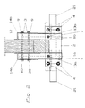
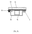
- Fig. 16 shows one of the essential features of the invention:
- An intermediate piece 1d which can be fastened to a rafters 12 carries, by means of a clamping action, a holder 10a to which an awning 6 is fastened in a manner known per se and a clamping plate 2a which is clamped to the wall holder 10a by means of clamping screws 4 via the intermediate piece 1d. Loosening these screws 4 allows the wall holder 10a and thus the awning 6 to be displaced vertically without any particular effort.
- a securing screw 13 is provided as a fuse, which is screwed through the clamping plate 2a into the intermediate piece 1d after completion of the assembly.
- an assembly screw 18 is shown, on which the intermediate piece 1d initially hangs in the course of assembly.
- a second mounting screw 20 is screwed into the rafters 12 through a second hole in the intermediate piece 1d.
- the relative angular position of the intermediate piece 1 to the roof pitch is determined by the screws 18 and 20. If necessary, the intermediate piece 1d could be pivoted about the mounting screw 18 to change this angle, it then being possible to lock it in this pivoting position by screwing the second mounting screw 20 into the rafters 12 again.
- this structure is not suitable for frequent swivel position adjustment, since loosening and tightening the mounting screw 20 or the correspondingly required bores in the rafters 12 weaken the same.
- the second mounting screw 20 can also be screwed into the rafters 12, but alternatively also by tightening a thread or a nut in or on the intermediate piece 1, tightening and fixing the swivel angle position, allowed without additional weakening of the rafters 12.
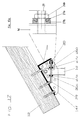
- the rafters 12 is also reinforced in the area of the awning mounting device by a specially designed mounting shoe 14a, which has two mounting surfaces 15, in which a plurality of bores 8a are arranged. Through these holes, the mounting shoe 14a can be screwed onto the side of a rafter or the like.
- a holding surface 16 of the shoe 14 has bores 8b of the same type which allow additional fastening to the rafters, but do not necessarily have to be provided.
- a pivot groove 19 is also formed in the holding surface 16, in which the second mounting screw 20 can pivot about the mounting screw 18.
- the mounting screw 18 passes through a bore 17 in the holding surface 16, the intermediate piece 1 and the rafters 12.
- a nut may be screwed to the mounting screw 18.
- the mounting screw 18 can also be a wood screw.
- the hatched part in the area of the clamping plate 2 shows washers 3, the clamping screws 4 and spacer sleeves 5, the elongated extent of which is somewhat smaller than the clamping width K of the intermediate piece 1.
- the spacer sleeves 5 avoid the risk of overstressing the intermediate piece 1 due to excessive clamping the clamping screws 4.
- the intermediate piece 1 is closed off by an optionally provided end wall 7, which is provided for optical reasons, but also leads to an additional stiffening of the intermediate piece 1 in the clamping area.
- the structure according to FIG. 2 shows a double assembly of two intermediate pieces 1a and 1b on the side of a rafter 12 using two identical assembly shoes 14a and 14b by means of two continuous assembly screws 18 and 20, which are secured by nuts.
- the clamping plate 2 is so wide that both spacers can be clamped between it and the wall bracket.
- the clamping screws 4 are so far apart from each other that a stiffening piece 21, for example a mounting tube of an awning, can be pushed between them, which is also clamped after tightening the screws 4.
- a stiffening piece 21 for example a mounting tube of an awning
- Two securing screws 13a and 13b secure the position of the components relative to one another after assembly is complete.
- FIG. 4 also shows a further auxiliary construction possibility, in which a stiffening piece - which can also be continuous - between a narrow clamping plate 2b with a clamping screw 4b and a continuous one Holder 10 can be clamped, while the stiffening piece 21 is also clamped at its other end in the region of an intermediate piece 1.
- the assembly process according to FIG. 5 with an assembly shoe 14a can, as mentioned, be modified by shortening the assembly screw 20 and only passing through the holding surface 16 and a side wall of the intermediate piece 1.
- a thread or a nut, not shown, is fastened in or on the latter in order to allow the screw 20 to be tightened.
- the assembly shoe 14c shown in FIGS. 8 and 9 has a base leg 22 and two lateral leg surfaces 23, in which the bores 17 and the recesses 19 are provided.
- this shoe 14c In order to increase the strength of this shoe 14c, it can be closed on its front and on its back, if not shown in more detail. It can also have stiffening ribs.
- This component is preferably made of cast aluminum or the like.
- FIGS. 10a to 10c show possibilities resulting from the shoe 14c for pivoting the intermediate piece relative to the roof pitch.
- FIG. 11 A further shoe variant results from FIG. 11, in which an angle piece comprises a rafters from below and from the side.
- This angle piece or this assembly shoe 14d has the comparable possibilities as the assembly shoe 14a and 14b, it being able to be attached to the rafters 12 both laterally and from below.
- the intermediate piece 1 is enlarged by a widening contact surface 25, which also optionally has the possibility of screwing a locking screw 13 into the shoe 14d.
- FIG. 12 A further special assembly shoe 14e is shown in FIG. 12, which, based on the assembly shoe 14f in FIG. 17, has an adjustment rod 29 which has a thread or adjustment nuts 26 which pivotally adjust between the lower region of the assembly shoe 14e and the intermediate piece 1d allow.
- the mounting shoe 14e can, as shown in FIG. 12, be designed as a pure L-shaped angle, or also, for example in FIG. 17 (14f), essentially correspond to a structure comparable to an mounting shoe 14c according to FIGS. 8 and 9.
- the fastening of the adjusting rod 29 in or on the shoe 14e or 14f must be rotatable, the intermediate piece 1d preferably having elongated holes in the region of the adjusting rod 29.
- FIG. 13 refers to a completely different variant of the invention, in which a mounting shoe 14g is mounted on a rafter both laterally and from below.
- a clamping tab 30 is provided, which can be screwed onto the shoe by means of screws 31 and, if appropriate, simultaneously on the rafters 12.
- the clamping tab 30 allows vertical play of an intermediate piece 1e, which can be fixed in the clamping tab 30 by a mounting screw 18.
- a pressure screw (not shown) is also conceivable, which, guided in a thread in the clamping tab, only presses on the side wall of the intermediate piece 1e.
- FIG. 14 shows a variant for fastening the clamping plate, in which a clamping plate 2 has an abutment 32, in which an opposing engagement piece 33 of a mounting bracket 2e engages. Between the components 2e and 2c, the intermediate piece 1a is clamped in a known manner.
- FIG. 15 shows an additional possibility of stiffening a mounting shoe 14c on the side of a rafters 12.
- a stiffening plate 24 in this case angled at an angle, is provided, which is fastened both to the mounting shoe 14c and to the side wall of the rafter 12.
- Fig. 18 symbolically shows two different awning assemblies, the lower assembly being carried out using two assembly shoes 14c, which in this case lie on the same level as the awnings previously installed or shown.
- an awning construction is preferably selected which has a mounting tube which is clamped between the clamping plates on the intermediate pieces 1.
- the awning itself is only dashed, its possible left or right end indicated by two angled brackets.
- a second awning installation option on a roof can also be seen from FIG. 18, an assembly shoe 14c being mounted there open upwards, so that the intermediate piece 1 projects vertically upwards.
- the intermediate piece 1 is in any case provided with an end wall 7 in this embodiment.
- a seal 34 is also provided, which protects against water ingress below the roof tiles.
- FIG. 19 The fact that the invention also enables the installation of an awning through a hollow roof or through a suspended ceiling 35 is shown in FIG. 19.
- FIG. 20 shows a variant of the infinitely variable adjustability of an awning 6 along an intermediate piece 1, a clamping sleeve 36 being provided here instead of clamping plates and being displaceably mounted on the intermediate piece 1.
- Two clamping screws 4b which are screwed into a threaded bore in a reinforced side wall of the clamping sleeve 36, press on a side wall of the intermediate piece 1 in order to fix the clamping sleeve thereon.
- the clamping sleeve 36 has a connecting piece 37 which is connected directly to the wall bracket 10 via an inverted wall bracket 38 or in a constructionally modified manner.
- the connection is provided by a connecting screw 39 which, on the one hand, allows lateral displacement, but on the other hand also allows the wall bracket 10 and thus the awning 6 to pivot slightly relative to the intermediate piece 1.
- telescopic intermediate pieces 1g, h telescopic intermediate pieces 1g, h.
- the clamping mechanism for mutually clamping the two telescopic parts or intermediate piece parts 1g or 1h functions as follows, for example:
- the intermediate piece 1g is closed at an open end by means of a plug 52 which serves a bore 56 for supporting a screw head of a screw 53.
- the intermediate piece 1g is slotted in a cross shape, the slots 54 serving to spread the intermediate piece in this area, while the other slot-like recesses 55 serve to enable the penetration of screws which either attach the intermediate piece to a component 12 or to a holder 10 fasten.
- the recesses 55 or the bore 56 are laterally offset from the center, since the screw 53 is inserted through the bore 56, which cooperates at its screw end with a threaded bore 57 in a wedge-shaped block 51.
- the block 51 has wedge-shaped clamping or spreading pins which engage in the slots 54 and spread them apart depending on the rotational position of the screw 53.
- a security screw 13 can enforce both the intermediate piece 1h and 1g for additional security.
Abstract
Description
Die Erfindung betrifft eine Montagevorrichtung für einen Sonnenschutz, insbesondere für eine Markise. Unter Sonnenschutz im Sinne der Erfindung sind Vorrichtungen zu verstehen, die in Abhängigkeit von Wetterbedingungen bzw. in Abhängigkeit von Wünschen der jeweiligen Anwender ausgefahren oder eingezogen werden. Insbesondere sind darunter auch Markisen zu verstehen, wie sie weltweit in den verschiedensten Formen bekannt sind.The invention relates to a mounting device for sun protection, in particular for an awning. Sun protection in the sense of the invention is to be understood as devices which are extended or retracted depending on weather conditions or depending on the wishes of the respective user. In particular, this also includes awnings as they are known in various forms worldwide.
Im folgenden wird beispielhaft insbesondere auf solche Markisen eingegangen, wobei dadurch der Schutzumfang der Patentansprüche nicht eingeschränkt ist. Weiters wird im besonderen auf die Problematik der Montage derartiger Markisen an Dächern eingegangen, wobei auch dieses nicht einschränkend ist, insofern als die Erfindung für die Montage von Sonnenschutzeinrichtungen an beliebigen Orten bzw. Bauteilen möglich ist. Dem Fachmann sind an den verschiedensten Orten bzw. Bauteilen entsprechende Probleme bekannt, die vergleichbar den angeführten Problemen bei der Dachmontage durch die Erfindung bestens gelöst werden können.In the following, examples of such awnings will be dealt with in particular, the scope of protection of the claims not being restricted thereby. Furthermore, the problem of installing such awnings on roofs is dealt with in particular, although this is also not restrictive insofar as the invention is possible for the installation of sun protection devices at any desired location or component. Corresponding problems are known to the person skilled in the art in a wide variety of locations or components, which can be solved by the invention in the best way, comparable to the problems mentioned for roof assembly.
Bei dem Versuch, Markisen an Dachsparren zu montieren, sind bisher folgende Probleme aufgetaucht:So far, the following problems have arisen when trying to mount awnings on rafters:
Herkömmliche Wand- oder Deckenhalter für Markisen, das sind Bauteile, die ein Montagerohr der Markise aufnehmen, wobei das Montagerohr die Mechanik der Markise trägt, verfügen über eine ebene Montagefläche, die mittels Schrauben an Wänden oder Decken befestigt werden kann, so dass das Montagerohr und damit die Markise in einem gewissen Abstand von der Wand bzw. Decke starr gehalten ist Bei Dachschrägen bzw. geneigten Dachsparren kann ein Wand- bzw. Deckenhalter dementsprechend nicht problemlos montiert werden, da dadurch das Montagerohr und damit die gesamte Markise entsprechend der Dach- bzw. Dachsparrenneigung eine ungeeignete Schieflage erhält. Ausserdem ist durch den relativ geringen Abstand der Montagefläche des Wand- bzw. Deckenhalters von der Markise ein Platzproblem im Dachbereich gegeben, das dazu führt, dass die Markise nicht ausgefahren werden kann.Conventional wall or ceiling brackets for awnings, these are components that hold a mounting tube of the awning, the mounting tube supporting the mechanism of the awning, have a flat mounting surface that can be attached to walls or ceilings by means of screws, so that the mounting tube and So that the awning is rigidly held at a certain distance from the wall or ceiling. In the case of sloping ceilings or inclined rafters, a wall or ceiling bracket can therefore not be easily fitted, as this causes the mounting tube and thus the entire awning to match the roof or Rafter pitch receives an unsuitable inclination. In addition, the Given the relatively small distance between the mounting surface of the wall or ceiling bracket and the awning, there is a space problem in the roof area, which means that the awning cannot be extended.
Um dieses Problem zu lösen, sind der Fachwelt verschiedene Methoden bekannt:Various methods are known to experts in order to solve this problem:
Die Dachsparrenbefestigung der Markise "Royal" der Firma Reflexa (eingetragenes Warenzeichen) ist ein L-förmiges Winkelstück, das mit seinem senkrechten Schenkel an einem Dachsparren seitlich angeschraubt werden kann, während an seinem horizontalen Schenkel ein Deckenhalter mit seiner Montagefläche angeschraubt werden kann. Die Neigung der Markise in bezug auf den Dachsparren kann dadurch gewählt werden, dass der vertikale Schenkel in unterschiedlichen Positionen am Dachsparren angeschraubt wird.The rafters of the "Royal" awning from Reflexa (registered trademark) is an L-shaped elbow that can be screwed to the side of a rafters with its vertical leg, while a ceiling bracket with its mounting surface can be screwed onto its horizontal leg. The inclination of the awning in relation to the rafters can be selected by screwing the vertical leg onto the rafters in different positions.
Der Nachteil dieser Variante ist, dass nach einmaliger Montage eine Höhenverstellung der Markise relativ zum Dach nicht mehr möglich ist. Würde eine Höhenverstellung gewünscht, müsste der L-förmige Schenkel vom Dachsparren losgeschraubt und tiefer versetzt werden. Da der Dachsparren nur eine beschränkte, eigene Höhe hat, ist dies nur mit einem gleichzeitigen Nach-vorn-rücken in Richtung des freiragenden Endes des Dachsparrens möglich, was möglicherweise aus architektonischen Gründen unerwünscht ist.The disadvantage of this variant is that after a single installation, it is no longer possible to adjust the height of the awning relative to the roof. If height adjustment were desired, the L-shaped leg would have to be unscrewed from the rafters and moved deeper. Since the rafters only have a limited height of their own, this is only possible by simultaneously moving forward towards the cantilevered end of the rafters, which may be undesirable for architectural reasons.
Eine vergleichbare Konstruktion mit den gleichen Nachteilen ist unter dem Handelsnamen "Markilux" bekannt geworden. Auch bei dieser Konstruktion ist lediglich ein Verschieben parallel zur Erstreckungsrichtung des Dachsparrens möglich, nicht jedoch ein Verschieben in der Senkrechten.A comparable construction with the same disadvantages has become known under the trade name "Markilux". With this construction too, only a movement parallel to the direction of extension of the rafters is possible, but not a movement in the vertical direction.
Eine andere Dachsparrenhalterung bietet ebenso eine starre Winkelkonstruktion zur Befestigung, zur seitlichen Befestigung am Dachsparren, unter Anwendung eines Deckenhalters.Another rafter bracket also offers a rigid angle construction for attachment, for lateral attachment to the rafter, using a ceiling bracket.
Gegenüber den vorbeschriebenen bekannten Ausführungen hat diese Montagevorrichtung eine zusätzliches Merkmal:Compared to the known designs described above, this mounting device has an additional feature:
Das im Deckenhalter gehaltene Montagerohr ist seitlich in der Horizontalen verschiebbar. Eine Adaption an Höhenverhältnisse ist aber auch bei dieser Montage nur unter der gleichen Problembelastung wie bei der vorbeschriebenen Konstruktionen möglich. Umgekehrt bringt dieser Aufbau den Nachteil mit sich, dass ein Montagerohr benutzt werden muss.The mounting tube held in the ceiling bracket can be moved laterally in the horizontal. An adaptation to height conditions is also possible with this assembly only under the same problem load as with the previously described constructions. Conversely, this structure has the disadvantage that an assembly tube must be used.
Dem gegenüber gibt es eine Konstruktion der Firma "Weinor", bei der, bei geeigneten Wandhaltern, auf ein Montagerohr verzichtet werden kann. Die erwähnte Konstruktion verfügt über einen L-förmigen Profilwinkel, der im Schnitt mit seinem normalerweise vertikalen Schenkel in die Waagrechte geschwenkt ist, so dass bei Montage dieses Schenkels seitlich an einem Dachsparren der normalerweise waagrechte Schenkel in Form einer vertikalen Platte etwa rechtwinkelig von der Seite des Dachsparrens abragt. Dieser Bauteil verfügt über eine gewisse Länge, entlang welcher der Wandhalter angeschraubt werden kann. Gemäss diesem Stand der Technik wird der Wandhalter nun dadurch angeschraubt, dass in die senkrechte Platte Löcher gebohrt werden, durch die die Befestigungsschrauben in den Wandhalter eingedreht werden.In contrast, there is a construction from the "Weinor" company, which, with suitable wall brackets, can do without an assembly tube. The construction mentioned has an L-shaped profile angle, which is pivoted on average with its normally vertical leg into the horizontal, so that when this leg is mounted on the side of a rafter, the normally horizontal leg in the form of a vertical plate is approximately at right angles from the side of the Rafters protrudes. This component has a certain length along which the wall bracket can be screwed on. According to this prior art, the wall bracket is now screwed on by drilling holes in the vertical plate through which the fastening screws are screwed into the wall bracket.
Alle diese Aufbauten bedingte als Nachteil, dass an der Baustelle in relativ aufwendigen Messverfahren zunächst bestimmt werden muss, wo der L-förmige Winkel und alle anderen Dachsparrenhalter seitlich am Dachsparren befestigt werden können und wo die Bohrungen zum Anschrauben des Wandhalters gesetzt werden müssen. Kommt es hierbei zu geringen Montageverfehlungen, führt dies zu einer schiefen Montage der Markise.All of these structures had the disadvantage that it must first be determined at the construction site in relatively complex measuring procedures where the L-shaped bracket and all other rafter brackets can be attached to the side of the rafters and where the holes for screwing on the wall bracket must be made. If there are minor assembly failures, this leads to an inclined installation of the awning.
Von den beschriebenen Konstruktionsarten ausgehend stellt sich der Erfindung nun die Aufgabe, eine Montagevorrichtung zu schaffen, die mit wenig Aufwand zu montieren ist und bei der im montierten Zustand mit wenig Aufwand Justierungen bzw. Korrekturen vorgenommen werden können.Starting from the types of construction described, the task of the invention is now an assembly device to create that can be assembled with little effort and in the assembled state with which adjustments or corrections can be made with little effort.
Gelöst wird diese Aufgabe durch die Kombination der Merkmale des Anspruches 1.This object is achieved by the combination of the features of
Unter länglichem Zwischenstück ist ein stangenförmiger Bauteil, zum Beispiel ein Montagerohr oder dergleichen zu verstehen, das an einem Ende an dem Bauteil - im beispielhaft beschriebenen Fall dem Dachsparren - befestigbar ist und im Bereich des anderen Endes den Wandhalter in stufenlos höhenverstellbarer Form aufnimmt.An elongated intermediate piece is to be understood as a rod-shaped component, for example a mounting tube or the like, which can be fastened at one end to the component - in the case described as an example, the rafters - and in the area of the other end accommodates the wall bracket in a continuously adjustable form.
Für die stufenlose Höhenverstellung gemäss vorliegender Erfindung sind dem Fachmann verschiedene Varianten vorstellbar, von denen einige im folgenden beispielhaft herausgegriffen beschrieben werden.Various variants are conceivable for the person skilled in the art for the infinitely variable height adjustment according to the present invention, some of which are described below by way of example.
In den abhängigen Patentansprüchen sind besondere Ausbildungsformen der Erfindung beschrieben bzw. gekennzeichnet, aus denen sich folgende Vorteile ergeben:In the dependent claims, special forms of training of the invention are described or characterized, from which the following advantages result:
Die Ausbildung nach Anspruch 2 ermöglicht eine einfache Montage, derart, dass die Klemmplatte zum Halter in einem genügend grossen Abstand vorbefestigt wird, so dass die Markise zusammen mit Halter und Klemmplatte an vorbefestigte Zwischenstücke aufgeschoben und anschliessend daran festgezogen werden kann.The embodiment according to
Die Variante nach Anspruch 3 sichert eine gute Kraftverteilung beim Anspannen der Spannschrauben, so dass eine Überanstrengung des Zwischenstückes durch zu hohen Einspanndruck vermieden wird.The variant according to
Die Sicherung gemäss Anspruch 4 ist kostengünstig herstellbar, indem nach vollbrachter Montage lediglich pro Wandhalter bzw. Klemmplatte vor Ort eine Gewindebohrung gesetzt wird, in die eine zusätzliche Sicherungsschraube eingeschraubt wird. Solche Sicherungsschrauben empfehlen sich vor allem dort, wo mit starken Windbelastungen bzw. Vibrationen zu rechnen ist.The fuse according to
Die Variante nach Anspruch 5 ist insofern eine montagesicherere Variante, als sie darauf Rücksicht nimmt, dass Dachsparren beispielsweise über eine verringerte Materialfestigkeit verfügen, so dass das Einschrauben von Montageschrauben unsicher ist bzw. zu einer unerwünschten Schwächung des Dachsparrens führt. Durch die Massnahmen des Anspruches 5 kann diese Schwächung optimal ausgeglichen werden.The variant according to
Die Variante nach Anspruch 6 erleichtert die Montage insofern, als die Winkeleinstellung des Zwischenstückes in bezug auf die Dachneigung erst nach der Montage der Markise vorgenommen werden kann bzw. jederzeit auch wieder verändert werden kann. Die Montageschraube dient dabei als Drehlager bzw. als Schwenklager für das Zwischenstück und die Markise. Der erfindungsgemässe Montageschuh mit dem darin schwenk- und fixierbar gehaltenen Zwischenstück ist auch unabhängig von den übrigen Erfindungsmerkmalen verwendbar und kann beispielsweise nach einer weiteren Ausgestaltung auch für das Verändern der Markisenneigung zu unterschiedlichen Zeiten herangezogen werden, etwa durch eine nicht näher dargestellt Mechanik, die es einem Anwender erlaubt, die zweite Montageschraube zu lockern und nach einer Neigungsveränderung wieder anzuziehen.The variant according to
Dies trifft insbesondere auf die bevorzugte Ausführung gemäss Anspruch 7 zu.This applies in particular to the preferred embodiment according to
Die Ausbildung gemäss Anspruch 8 erlaubt eine Variante, bei der zusätzlich zum Befestigen der Markise an dem senkrechten Zwischenstück das Befestigen von waagrechten Montagerohren oder dergleichen bzw. Versteifungsstücken, die zur verbesserten Steifigkeit beitragen, möglich ist.The embodiment according to claim 8 allows a variant in which, in addition to attaching the awning to the vertical intermediate piece, it is also possible to attach horizontal mounting tubes or the like or stiffening pieces which contribute to improved rigidity.
Die Ausbildung gemäss Anspruch 9 hilft, bei der Dachsparrenmontage eine besonders stabile Befestigung an zwei Zwischenstücken, die eine entsprechende Erhöhung der Zugfestigkeit und Rüttelsicherheit mitsichbringen, zu erreichen.The design according to
Die Ausbildung nach Anspruch 10 erhöht die Stabilität der gesamten Markisenkonstruktion insgesamt und reduziert allfällige Bewegungsmöglichkeiten derselben im Hinblick auf unbeabsichtigt auftretende Bewegungen der Dachsparren untereinander. (Solche Bewegungen können temperatur- oder feuchtigkeitsinduziert sein.)The design according to
Belastungen der übrigen Markisenkonstruktion werden dadurch reduziert.This reduces loads on the rest of the awning construction.
Die Ausbildung nach Anspruch 11 beschreibt einen einfach herzustellenden Montageschuh mit guten Montageeigenschaften, während Anspruch 12 eine Variante des Montageschuhs offenbart, die vor allem für die Befestigung an der Unterseite eines Bauteils, zum Beispiel eines Dachsparrens, aber auch für die Befestigung auf dem Dach geeignet ist.The design according to
Die Variante nach Anspruch 13 erhöht bei einem an der Unterseite eines Dachsparrens befestigten Montageschuh die Haltekraft am Dachsparren.The variant according to
Die Variante gemäss Anspruch 14 dient ebenso der Erhöhung der Markisensteifigkeit nach Montage und bietet insbesondere die Möglichkeit, auch in Bereichen, bei denen keine Dachsparren zur Verfügung stehen, einer unterstützenden Befestigung der Markise.The variant according to
Die Detailvariante nach Anspruch 15 ermöglicht das stufenlose Einstellen des Winkels zwischen Zwischenstück und Dachneigung.The detailed variant according to
Anhand von beispielhaften Figuren werden das Wesen der Erfindung sowie weitere spezielle Ausführungsformen beschrieben.The essence of the invention and further special embodiments are described on the basis of exemplary figures.
Es zeigen dabei:
- Fig.1
- einen Dachsparren mit erfindungsgemässem Montageschuh und montierter Markise;
- Fig.2
- eine Ansicht mit breiter Klemmplatte bzw. mit Halter und beidseitiger Montage an einem Dachsparren;
- Fig.3
- eine Ansicht von zwei Dachsparren mit daran montierten erfindungsgemässen Montagevorrichtungen;
- Fig.4
- einen vergleichbaren Aufbau zu Fig.3 in der Draufsicht mit im Unterschied dazu durchgehendem Wandhalter, an dem auch zwischen zwei Dachsparren mittels Klemmplatte eine Befestigung an einem Versteifungsstück vorgenommen ist, das einerends zwischen einer doppelt verwendeten Klemmplatte und dem Wandhalter eingeklemmt ist. Diese Klemmplatte ist nämlich gleichzeitig mit dem Zwischenstück, das am Dachsparren befestigt ist, verspannt. Die in dieser Figur dargestellte Ausführung kann auch auf einen durchgehenden Wandhalter verzichten, sofern im Bereich der zusätzlichen Klemmplatte ein eigener Wandhalter vorgesehen ist;
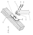
- Fig.5
- zeigt einen Dachsparren mit explosionsartig dargestelltem Montagevorgang des Zwischenstückes im Montageschuh;
- Fig.6
und 10 - zeigen mögliche Schwenkpositionen von Zwischenstücken bei unterschiedlichen Montageschuhen;
- Fig.7
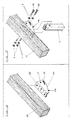
- zeigt einen einstückig aus abgekantetem Blech hergestellten Montageschuh in Schrägansicht;
- Fig.8
- einen anderen Montageschuh, der beispielsweise auch aus Aluguss oder dergleichen hergestellt sein kann;
- Fig.9
- den explosionsartig dargestellten Montagevorgang mit einem Montageschuh gemäss Fig.8;
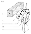
- Fig.11
- eine weitere Variante eines Montageschuhs, der eine seitliche Montage eines Zwischenstückes erlaubt;
- Fig.12
- eine weitere Variante eines Montageschuhs mit stufenloser Verstellbarkeit des Schwenkwinkels zwischen Dachneigung und Zwischenstück;
- Fig.13
- eine weitere Variante eines Montageschuhs mit Führungslasche und darin stufenlos höhenverstellbarem Zwischenstück;
- Fig.14
- eine weitere Variante mit nur einseitiger Klemmschraubverbindung;
- Fig.15
- einen Aufbau mit zusätzlicher Montageversteifung eines Montageschuhs;
- Fig.16
- eine Seitenrissansicht durch ein Dach mit montiertem Zwischenstück und daran stufenlos höhenverstellbarer Markise;
- Fig.17
- eine weitere Variante eines Montageschuhs mit integrierter stufenloser Verschwenkbarkeitseinstellung des Zwischenstücks;
- Fig.18
- eine Variante mit Aufdachmontage und einer zusätzlichen Variante mit Unterfirstmontage;
- Fig.19
- eine beispielhafte erfindungsgemässe Montage einer Markise durch ein Hohldach; und
- Fig.20
- eine Variante mit stufenloser Höhenverstellung über Klemmschrauben an einem Zwischenstück.
- Fig.21
- eine Variante mit Klemmbügeln, die an Nutensteinen in Nuten eines Wandhalters mit der Markise verbunden sind; und
- Fig.22
- ein erfindungsgemässes Zwischenstück zur stufenlosen Längenverstellung des Zwischenstückes.
- Fig. 1
- a rafters with a mounting shoe according to the invention and a mounted awning;
- Fig. 2
- a view with a wide clamping plate or with holder and double-sided mounting on a rafters;
- Fig. 3
- a view of two rafters with mounting devices according to the invention mounted thereon;
- Fig. 4
- a comparable structure to Figure 3 in plan view with in contrast to this continuous wall bracket, on which between two roof rafters by means of a clamping plate is attached to a stiffening piece which is clamped at one end between a double-used clamping plate and the wall bracket. This clamping plate is namely braced at the same time with the intermediate piece which is attached to the rafters. The embodiment shown in this figure can also dispense with a continuous wall bracket, provided that a separate wall bracket is provided in the area of the additional clamping plate;
- Fig. 5
- shows a rafters with an exploded assembly process of the intermediate piece in the assembly shoe;
- Fig. 6 and 10
- show possible pivot positions of intermediate pieces with different assembly shoes;
- Fig. 7
- shows an integral shoe made of folded sheet metal in an oblique view;
- Fig. 8
- another assembly shoe, which can also be made of cast aluminum or the like, for example;
- Fig. 9
- the exploded assembly process with an assembly shoe according to Figure 8;
- Fig. 11
- a further variant of an assembly shoe, which allows lateral mounting of an intermediate piece;
- Fig. 12
- a further variant of an assembly shoe with stepless adjustability of the swivel angle between roof pitch and intermediate piece;
- Fig. 13
- a further variant of an assembly shoe with a guide strap and an infinitely height-adjustable intermediate piece therein;
- Fig. 14
- another variant with only one-sided clamping screw connection;
- Fig. 15
- a structure with additional assembly stiffening of an assembly shoe;
- Fig. 16
- a side elevation view through a roof with a mounted intermediate piece and there continuously adjustable awning;
- Fig. 17
- another variant of an assembly shoe with integrated stepless pivoting adjustment of the intermediate piece;
- Fig. 18
- a variant with on-roof installation and an additional variant with under-ridge installation;
- Fig. 19
- an exemplary inventive assembly of an awning through a hollow roof; and
- Fig. 20
- a variant with stepless height adjustment using clamping screws on an intermediate piece.
- Fig. 21
- a variant with clamps, which are connected to the awning by means of sliding blocks in the slots of a wall bracket; and
- Fig. 22
- an intermediate piece according to the invention for stepless length adjustment of the intermediate piece.
In den Figuren bedeuten die folgenden Bezugszeichen folgende Bauteile:
- 1a-1h
- wobei das Zwischenstück 1g und 1h zweiteilig ausgeführt und über einen eigenständig erfinderischen Mechanismus teleskopartig auseinanderziebar und arretierbar ist.
- 2
- Klemmplatte, kann auch als Klemmbügel o.dgl. ausgeführt sein. Bei bestimmten Anwendungen können auch zwei Klemmplatten vorgesehen sein, zwischen denen
ein Halter 10und ein Zwischenstück 1 festgeklemmt und dadurch verbunden sind. - 3
- Beilagscheiben
- 4
- Klemmschrauben
- 5
- Distanzstücke, insbesondere Distanzhülsen mit geringerer Längenerstreckung als der Klemmweg k des
Zwischenstücks 1 - 6
- Markise, symbolische Darstellung, eingehängt in
einen Halter 10, wie er beispielsweise auch als herkömmlicher Wandhalter ausgebildet ist, um an Mauern befestigt zu werden. - 7
- Abschlusswand des Zwischenstückes 1
- 8
- gestanzte Löcher für den Einsatz von Befestigungsschrauben; a) an
Montageflächen 15 desSchuhs 14a,b; b) anHalteflächen 16 desSchuhs 14a,b. Letztere werden nur optional beansprucht. - 9
- Mutter
- 10
- Halter, z.B. Wand- oder Deckenhalter einer Markise; dient normalerweise zur Befestigung derselben an einer Wand.
- 11
- Montagevorrichtung, insbesondere Markisenmontagevorrichtung;
- 12
- Bauteil, in den gezeigten Ausführungsbeispielen jeweils ein Dach bzw. Dachsparren eines Daches; kann jedoch auch jeder andere Bauteil sein, an dem eine Markise zu montieren ist, z.B. Kraftfahrzeug, Hauswand, usw.
- 13
- Sicherungsschraube, dafür wird in der Regel erst an der Baustelle ein Gewindeloch gebohrt.
- 14
- Montageschuh (Konsole)
- 15
- Montagefläche des Schuhs 14
- 16
- Haltefläche des Schuhs 14
- 17
- Bohrung
- 18
- Montageschraube
- 19
- Schwenkkurve
- 20
- zweite Montageschraube
- 21
- Versteifungsstück
- 22
- Basisschenkel
- 23
- abragender Schenkel
- 24
- Versteifungsplatte
- 25
- Anlagefläche
- 26
- Einstellmuttern
- 27
- sphärische Beilagscheiben
- 28
Drehpunkt für 29- 29
- Einstellstange
- 30
- Klemmlasche
- 31
- Schrauben
- 32
- Widerlager
- 33
- Eingreifstück
- 34
- Dichtung
- 35
- abgehängte Decke
- 36
- Klemmhülse
- 37
- Verbindungsstück
- 38
- umgekehrter Wandhalter
- 39
- Verbindungsschraube
- 40
- seitliche Montageausnehmung - in der Regel Bohrungen, durch die der Montageschuh 14f auch seitlich an einem Dachsparren oder dergleichen befestigt werden kann.
- 41
- verstärkte Wand von seitlich montierbarem Montageschuh 14f
- 42
- Nutenstein zum Einschub in
gegengleiche Nuten 43 auf der Rückseite desWandhalters 10b. Die Nutensteine werden zunächst auf Klemmbügel 44 geschraubt. - 43
- Nuten in
Rückseite des Wandhalters 10b. Diese können auch, wie an sich bekannt, über nach innen gerichtete stegartige Vorsprünge aufweisen, die in gegengleiche Nuten anden Nutensteinen 42 eingreifen,um dem Wandhalter 10b eine grössere Festigkeit im Bereich der Nuten 43 zu geben. - 44
- Klemmbügel aus gebogenem Rundstahl mit flachgepresstem
Mittelteil mit Gewinde 45 zurAufnahme von Klemmschrauben 47; anstelle der dargestellten Klemmbügel können auch vorgeformte Profilteile vorgesehen sein, die den Klemmbügel ähnlich an ihrer Wandhalterseite jedoch nutensteinähnlich ausgebildet sind, wodurch sie selbst indie Nuten 43 eingreifen. - 45
Gewindebohrung für Klemmschrauben 47- 46
- Gewinde am Klemmbügel zur Aufnahme der Nutensteine 42 mit den entsprechenden Gewindebohrungen
- 47
- Klemmschraube; diese haben an ihrem schraubenseitigen Ende vorzugsweise eine konische Anspitzung, um beim Festziehen gut in die Seitenwand des Zwischenstückes 1f zu drücken; alternativ können im Zwischenstück 1f auch Bohrungen oder Gewindebohrungen vorgesehen sein, um
mit den Klemmschrauben 47 zu kooperieren. - 48
- 49
- 50
- 51
- keilförmiger Spannklotz
- 52
- Stopfen zum Einpressen; wirkt als Gegenlager zum Spannklotz
- 53
- Spann- und Verstellschraube für Stopfen 52 und Spannklotz 51
- 54
- Spannuten, um dem Spannklotz das Aufweiten des Rohres zu ermöglichen
- 55
- Langloch für den
Durchsatz der Klemmschrauben 4oder Montageschrauben 18und 20, je nachdem, in welchem Bereich dieser Teil des Zwischenstückes eingesetzt wird. - 56
- Bohrung bzw. Sitz für Spann- und Verstellschraube
- 57
Gewindebohrung im Stopfen 51- 58
- Spann- bzw. Spreizzapfen mit keilförmiger Ausbildung zum Spreizen der Spannuten 54
- 1a-1h
- wherein the
intermediate piece 1g and 1h are made in two parts and can be telescopically pulled apart and locked via an independent inventive mechanism. - 2nd
- Clamping plate, can also be used as a clamp or the like. be executed. In certain applications, two clamping plates can also be provided, between which a
holder 10 and anintermediate piece 1 are clamped and thereby connected. - 3rd
- Washers
- 4th
- Clamping screws
- 5
- Spacers, in particular spacer sleeves with a smaller length than the clamping path k of the
intermediate piece 1 - 6
- Awning, symbolic representation, suspended in a
holder 10, as it is also designed as a conventional wall holder, for example, in order to be attached to walls. - 7
- End wall of the
intermediate piece 1 - 8th
- punched holes for the use of fastening screws; a) on mounting
surfaces 15 of theshoe 14a, b; b) on holdingsurfaces 16 of theshoe 14a, b. The latter are only claimed optionally. - 9
- mother
- 10th
- Holders, eg wall or ceiling brackets for an awning; is usually used to attach them to a wall.
- 11
- Mounting device, in particular awning mounting device;
- 12th
- Component, in the exemplary embodiments shown a roof or rafters of a roof; However, it can also be any other component on which an awning is to be installed, e.g. motor vehicle, house wall, etc.
- 13
- Locking screw, for this a threaded hole is usually only drilled at the construction site.
- 14
- Assembly shoe (console)
- 15
- Mounting surface of the
shoe 14 - 16
- Holding surface of the
shoe 14 - 17th
- drilling
- 18th
- Mounting screw
- 19th
- Swing curve
- 20th
- second mounting screw
- 21
- Stiffener
- 22
- Base leg
- 23
- protruding thigh
- 24th
- Stiffening plate
- 25th
- Contact surface
- 26
- Adjusting nuts
- 27
- spherical washers
- 28
- Pivotal point for 29
- 29
- Adjusting rod
- 30th
- Clamp tab
- 31
- Screws
- 32
- Abutment
- 33
- Engaging piece
- 34
- poetry
- 35
- suspended ceiling
- 36
- Clamping sleeve
- 37
- Connector
- 38
- inverted wall bracket
- 39
- Connecting screw
- 40
- Lateral mounting recess - usually holes through which the mounting shoe 14f can also be attached laterally to a rafters or the like.
- 41
- reinforced wall of mounting shoe 14f that can be mounted on the side
- 42
- Sliding block for insertion into opposing
grooves 43 on the back of thewall bracket 10b. The sliding blocks are first screwed onto clampingbracket 44. - 43
- Grooves in the back of the
wall bracket 10b. As is known per se, these can also have inwardly directed web-like projections which engage in mutually identical grooves on the slidingblocks 42 in order to give thewall bracket 10b greater strength in the region of thegrooves 43. - 44
- Clamping bracket made of curved round steel with flat pressed middle section with
thread 45 for receiving clamping screws 47; Instead of the clamping bracket shown, preformed profile parts can also be provided, which, like the clamping bracket on their wall holder side, are designed like a slot nut, as a result of which they themselves engage in thegrooves 43. - 45
- Threaded hole for clamping
screws 47 - 46
- Thread on the clamping bracket for receiving the sliding
blocks 42 with the corresponding threaded holes - 47
- Clamping screw; these preferably have a conical point at their screw-side end in order to press well into the side wall of the intermediate piece 1f when tightening; alternatively, bores or threaded bores can also be provided in the intermediate piece 1f in order to cooperate with the clamping screws 47.
- 48
- 49
- 50
- 51
- wedge-shaped clamping block
- 52
- Press-in plug; acts as a counter bearing to the clamping block
- 53
- Clamping and adjusting screw for
plug 52 and clampingblock 51 - 54
- Flutes to allow the pipe to expand
- 55
- Elongated hole for the throughput of the clamping screws 4 or mounting
screws - 56
- Hole or seat for tensioning and adjusting screw
- 57
- Threaded hole in the
plug 51 - 58
- Clamping or expanding spigot with a wedge-shaped design for expanding the
flutes 54
Die Figuren sind zusammenhängend beschrieben, gleiche Bezugszeichen bedeuten gleiche Bauteile; ähnliche Bauteile tragen gleiche Bezugszeichen mit unterschiedlichen Indizes.The figures are described coherently, the same reference symbols denote the same components; Similar components have the same reference numbers with different indices.
Fig.16 zeigt eines der Wesensmerkmale der Erfindung:Fig. 16 shows one of the essential features of the invention:
Ein an einem Dachsparren 12 befestigbares Zwischenstück 1d trägt mittels Klemmwirkung einen Halter 10a, an dem eine Markise 6 in an sich bekannter Weise befestigt ist und eine Klemmplatte 2a, die mittels Klemmschrauben 4 über das Zwischenstück 1d mit dem Wandhalter 10a verklemmt ist. Ein Lösen dieser Schrauben 4 ermöglicht das vertikale Versetzen des Wandhalters 10a und damit der Markise 6 ohne besonderen Aufwand.An
Als Sicherung ist eine Sicherungsschraube 13 vorgesehen, die nach beendeter Montage durch die Klemmplatte 2a in das Zwischenstück 1d geschraubt ist.A securing
Im oberen Ende des Zwischenstücks 1d ist eine Montageschraube 18 dargestellt, an der im Zuge der Montage das Zwischenstück 1d zunächst schwenkbar hängt. Durch eine zweite darunterliegende Bohrung im Zwischenstück 1d ist eine zweite Montageschraube 20 in den Dachsparren 12 eingeschraubt. Durch die Schrauben 18 und 20 wird die relative Winkellage des Zwischenstückes 1 zur Dachneigung bestimmt. Bei Bedarf könnte das Zwischenstück 1d um die Montageschraube 18 zur Veränderung dieses Winkels verschwenkt werden, wobei anschliessend durch neuerliches Einschrauben der zweiten Montageschraube 20 in den Dachsparren 12 eine Arretierung in dieser Schwenklage möglich ist. Dieser Aufbau ist natürlich nicht zu einer häufigen Schwenklagenverstellung geeignet, da das Lösen und Wiederanziehen der Montageschraube 20 bzw. die entsprechend notwendigen Bohrungen im Dachsparren 12 zu einer Schwächung desselben führen.In the upper end of the
Dem gegenüber zeigt Fig.1 eine Variante, bei der die zweite Montageschraube 20 zwar ebenso auch in den Dachsparren 12 eingedreht werden kann, jedoch alternativ auch durch Anbringung eines Gewindes oder einer Mutter in bzw. an dem Zwischenstück 1 das Festschrauben und Fixieren der Schwenkwinkellage, ohne zusätzliche Schwächung des Dachsparrens 12, erlaubt. Der Dachsparren 12 ist im Bereich der Markisenmontagevorrichtung darüber hinaus durch einen speziell ausgebildeten Montageschuh 14a verstärkt, der über zwei Montageflächen 15 verfügt, in denen mehrere Bohrungen 8a angeordnet sind. Durch diese Bohrungen kann der Montageschuh 14a an der Seite eines Dachsparrens oder dergleichen festgeschraubt werden. Eine Haltefläche 16 des Schuhs 14 verfügt über gleichartige Bohrungen 8b, die eine zusätzliche Befestigung am Dachsparren erlauben, jedoch nicht unbedingt vorgesehen sein müssen. In der Haltefläche 16 ist darüber hinaus eine Schwenknut 19 ausgebildet, in der die zweite Montageschraube 20 um die Montageschraube 18 schwenken kann. Die Montageschraube 18 durchsetzt dabei eine Bohrung 17 in der Haltefläche 16, dem Zwischenstück 1 und dem Dachsparren 12. An der anderen Seite des Dachsparrens ist gegebenenfalls eine Mutter mit der Montageschraube 18 verschraubt. Alternativ kann die Montageschraube 18 auch eine Holzschraube sein.1 shows a variant, in which the second mounting
Aus Fig.6 lassen sich verschiedene Schwenkpositionen entnehmen.Various swivel positions can be seen in FIG.
Der schraffierte Teil im Bereich der Klemmplatte 2 lässt Beilagscheiben 3, die Klemmschrauben 4 sowie Distanzhülsen 5 erkennen, deren längliche Erstreckung etwas kleiner ist, als die Klemmbreite K des Zwischenstückes 1. Die Distanzhülsen 5 vermeiden die Gefahr einer Überbeanspruchung des Zwischenstückes 1 durch zu starkes Klemmen der Klemmschrauben 4. An seinem unteren Ende ist das Zwischenstück 1 durch eine optional vorgesehene Abschlusswand 7 abgeschlossen, die aus optischen Gründen vorgesehen ist, jedoch auch zu einer zusätzlichen Versteifung des Zwischenstückes 1 im Klemmbereich führt.The hatched part in the area of the
Der Aufbau gemäss Fig.2 zeigt eine Doppelmontage von zwei Zwischenstücken 1a und 1b seitlich eines Dachsparrens 12 unter Anwendung zweier gleichartiger Montageschuhe 14a und 14b mittels zweier durchgehender Montageschrauben 18 und 20, die mittels Muttern gesichert sind. Die Klemmplatte 2 ist dabei so breit ausgeführt, dass beide Zwischenstücke zwischen ihr und dem Wandhalter eingeklemmt werden können. Die Klemmschrauben 4 sind so weit voneinander distanziert, dass zwischen ihnen ein Versteifungsstück 21, zum Beispiel ein Montagerohr einer Markise, durchgeschoben werden kann, das nach Anziehen der Schrauben 4 ebenso festgeklemmt ist. Mit dieser Ausführungsvariante ist es auch denkbar, die Klemmplatte 2 nicht mit einem Wandhalter 10 der Markise gegenzuklemmen, sondern mit einer weiteren Klemmplatte 2. Ist die Markise nämlich in bekannter Weise auf dem Versteifungsteil bzw. Montagerohr 21 befestigt, kann sie nun zwischen den beiden Klemmplatten 2 sowohl seitlich stufenlos als auch vertikal stufenlos verstellt werden.The structure according to FIG. 2 shows a double assembly of two
Die Stabilität ist dadurch nochmals erhöht und die Lösung ist somit für einen äusserst flexiblen Einsatz gefunden. Zwei Sicherungsschrauben 13a und 13b sichern nach vollbrachter Montage die Position der Bauteile zueinander.This further increases the stability and the solution has been found for extremely flexible use. Two securing
Für unterschiedliche Rastermasse (Abstand der Dachsparren zueinander) ergibt sich eine stufenlose Verstellbarkeit durch die Ausbildung gemäss Fig.3, bei der an wenigstens einer von zwei benachbarten Montagevorrichtungen eine breite Klemmplatte vorgesehen ist, die eine Auswahl der Klemmpositionen des Zwischenstückes erlaubt.For different grid dimensions (spacing of the rafters from one another) there is an infinitely variable adjustability through the design according to FIG. 3, in which a wide clamping plate is provided on at least one of two adjacent mounting devices, which allows a selection of the clamping positions of the intermediate piece.
Die Draufsicht von Fig.4 zeigt ebenso eine weitere Hilfskonstruktionsmöglichkeit, bei der ein Versteifungsstück - das auch durchgehend sein kann - zwischen einer schmalen Klemmplatte 2b mit Klemmschraube 4b und durchgehendem Halter 10 festklemmbar ist, während das Versteifungsstück 21 an seinem anderen Ende im Bereich eines Zwischenstückes 1 ebenfalls festgeklemmt ist.The top view of FIG. 4 also shows a further auxiliary construction possibility, in which a stiffening piece - which can also be continuous - between a
Der Montagevorgang gemäss Fig.5 mit einem Montageschuh 14a kann, wie erwähnt, dadurch abgeändert werden, dass die Montageschraube 20 verkürzt ist und lediglich die Haltefläche 16 und eine Seitenwand des Zwischenstückes 1 durchsetzt. In oder an letzterer ist ein Gewinde oder eine nicht dargestellte Mutter befestigt, um das Festspannen der Schraube 20 zu ermöglichen.The assembly process according to FIG. 5 with an
Der in Fig.8 und Fig.9 gezeigte Montageschuh 14c verfügt über einen Basisschenkel 22 und zwei seitliche Schenkelflächen 23, in welch letzteren die Bohrungen 17 und die Ausnehmungen 19 vorgesehen sind.The
Zur Erhöhung der Festigkeit dieses Schuhs 14c kann dieser an seiner Vorderseite und an seiner Rückseite, wenn nicht näher dargestellt, geschlossen ausgeführt sein. Er kann auch über Versteifungsrippen verfügen. Bevorzugt ist dieser Bauteil aus Aluminiumguss oder dergleichen hergestellt.In order to increase the strength of this
Die Fig.10a bis Fig.10c zeigen sich aus dem Schuh 14c ergebende Möglichkeiten zum relativen Schwenken des Zwischenstückes zur Dachneigung.FIGS. 10a to 10c show possibilities resulting from the
Eine weitere Schuhvariante ergibt sich aus Fig.11, bei der ein Winkelstück von unten und seitlich einen Dachsparren umfasst. Dieses Winkelstück bzw. dieser Montageschuh 14d verfügt über die vergleichbaren Möglichkeiten wie der Montageschuh 14a und 14b, wobei er sowohl seitlich als auch von unten am Dachsparren 12 befestigt werden kann. An seinem oberen Ende ist das Zwischenstück 1 durch eine verbreiternde Anlagefläche 25 vergrössert, die auch optional über die Möglichkeit des Einschraubens einer Sicherungsschraube 13 in den Schuh 14d verfügt.A further shoe variant results from FIG. 11, in which an angle piece comprises a rafters from below and from the side. This angle piece or this assembly shoe 14d has the comparable possibilities as the
Ein weiterer spezieller Montageschuh 14e ist in Fig.12 dargestellt, wobei dieser in Anlehnung an den Montageschuh 14f in Fig.17 über eine Einstellstange 29 verfügt, die über ein Gewinde bzw. über Einstellmuttern 26 verfügt, die eine Schwenkverstellung zwischen dem unteren Bereich des Montageschuhs 14e und dem Zwischenstück 1d erlauben. Eine solche Ausgestaltung eignet sich auch zum beliebigen Verstellen der Neigung nach Wunsch des Anwenders auch im Zeitraum nach der Montage der Markise. Der Montageschuh 14e kann dabei, wie in Fig.12 dargestellt, als reiner L-förmiger Winkel ausgebildet werden, oder auch beispielsweise in Fig.17 (14f) im wesentlichen einem Aufbau vergleichlich einem Montageschuh 14c gemäss Fig.8 und Fig.9 entsprechen.A further
Wie aus Fig.17 deutlicher zu sehen ist, muss die Befestigung der Einstellstange 29 im bzw. am Schuh 14e bzw. 14f drehbar sein, wobei bevorzugt das Zwischenstück 1d im Bereich der Einstellstange 29 über Langlöcher verfügt.As can be seen more clearly from FIG. 17, the fastening of the adjusting
Günstig ist es, wenn im Bereich der Einstellmuttern 26a und 26b sphärische Beilagscheiben 27 mit den entsprechenden Gegenstücken vorgesehen sind.It is favorable if spherical washers 27 with the corresponding counterparts are provided in the area of the adjusting nuts 26a and 26b.
Die Fig.13 nimmt Bezug auf eine gänzlich andere Variante der Erfindung, bei der ein Montageschuh 14g sowohl seitlich als auch von unten an einem Dachsparren montiert wird. Kompatibel zu diesem Schuh 14g ist eine Klemmlasche 30 vorgesehen, die mittels Schrauben 31 am Schuh und gegebenenfalls gleichzeitig am Dachsparren 12 angeschraubt werden kann. Die Klemmlasche 30 erlaubt ein vertikales Spiel eines Zwischenstückes 1e, das durch eine Montageschraube 18 in der Klemmlasche 30 fixiert werden kann. Alternativ zur Montageschraube 18 ist auch eine nicht dargestellte Druckschraube vorstellbar, die, in einem Gewinde in der Klemmlasche geführt, lediglich auf die Seitenwand des Zwischenstückes 1e drückt.FIG. 13 refers to a completely different variant of the invention, in which a mounting shoe 14g is mounted on a rafter both laterally and from below. Compatible with this shoe 14g, a
Fig.14 zeigt eine Variante zur Klemmplattenbefestigung, bei der eine Klemmplatte 2 über ein Widerlager 32 verfügt, in das ein gegengleiches Eingreifstück 33 eines Montagebügels 2e eingreift. Zwischen den Bauteilen 2e und 2c ist das Zwischenstück 1a in bekannter Weise eingeklemmt.FIG. 14 shows a variant for fastening the clamping plate, in which a
Der Aufbau gemäss Fig.15 zeigt eine zusätzliche Versteifungsmöglichkeit eines Montageschuhs 14c seitlich an einem Dachsparren 12. Dazu ist eine, in diesem Fall winkelig gekröpfte, Versteifungsplatte 24 vorgesehen, die sowohl am Montageschuh 14c als auch an der Seitenwand des Dachsparrens 12 befestigt ist.The structure according to FIG. 15 shows an additional possibility of stiffening a mounting
Fig.18 zeigt symbolhaft zwei unterschiedliche Markisenmontagen, wobei die untere Montage über zwei Montageschuhe 14c vorgenommen wird, die in diesem Fall zum Unterschied zu den bisherigen montierten bzw. dargestellten Markisen in derselben Ebene wie dieselben liegen. Infolge der relativ grossen Spannweite, die ein derartiger Aufbau erwarten lässt, wird dabei bevorzugt eine Markisenkonstruktion gewählt, die über ein Montagerohr verfügt, das zwischen Klemmplatten an den Zwischenstücken 1 festgespannt ist.Fig. 18 symbolically shows two different awning assemblies, the lower assembly being carried out using two
Die Markise selbst ist nur strichliert, deren mögliches linkes oder rechtes Ende durch zwei abgewinkelte Klammern angedeutet.The awning itself is only dashed, its possible left or right end indicated by two angled brackets.
Eine zweite Markisenmontagemöglichkeit auf einem Dach ist aus Fig.18 ebenso ersichtlich, wobei dort ein Montageschuh 14c nach oben offen montiert wird, so dass das Zwischenstück 1 senkrecht nach oben abragt. Zur Vermeidung von Feuchtigkeitseintritt in das Dach ist bei dieser Ausführung das Zwischenstück 1 jedenfalls mit einer Endwand 7 versehen. Rund um das Zwischenstück 1 ist ausserdem eine Dichtung 34 vorgesehen, die gegen Wasserzutritt unterhalb der Dachziegeln schützt.A second awning installation option on a roof can also be seen from FIG. 18, an
Dass die Erfindung auch die Montage einer Markise durch ein Hohldach hindurch bzw. durch eine abgehängte Decke 35 ermöglicht, ist in Fig.19 verdeutlicht.The fact that the invention also enables the installation of an awning through a hollow roof or through a suspended ceiling 35 is shown in FIG. 19.
Die Fig.20 zeigt eine Variante der stufenlosen Verstellbarkeit einer Markise 6 entlang eines Zwischenstückes 1, wobei hier anstelle von Klemmplatten eine Klemmhülse 36 vorgesehen ist, die verschieblich auf dem Zwischenstück 1 gelagert ist.20 shows a variant of the infinitely variable adjustability of an
Zwei Klemmschrauben 4b, die in einer Gewindebohrung in einer verstärkten Seitenwand der Klemmhülse 36 eingeschraubt sind, drücken auf eine Seitenwand des Zwischenstückes 1, um die Klemmhülse daran zu fixieren.Two clamping
Die Klemmhülse 36 verfügt an der anderen Seite über ein Verbindungsstück 37, das über einen umgekehrten Wandhalter 38 oder konstruktiv abgeändert direkt mit dem Wandhalter 10 verbunden ist. In der dargestellten Variante ist die Verbindung durch eine Verbindungsschraube 39 gegeben, die einerseits ein seitliches Verschieben, andererseits aber auch ein leichtes Schwenken des Wandhalters 10 und damit der Markise 6 gegenüber dem Zwischenstück 1 erlaubt.On the other side, the clamping
Gemäss Fig.22 liegen im Rahmen der Erfindung auch teleskopartige Zwischenstücke 1g,h. Der Klemmechanismus zum gegenseitigen Verklemmen der beiden Teleskopteile bzw. Zwischenstückteile 1g bzw. 1h funktioniert beispielhaft wie folgt:According to FIG. 22, telescopic intermediate pieces 1g, h. The clamping mechanism for mutually clamping the two telescopic parts or
Das Zwischenstück 1g ist an einem offenen Ende mittels Stopfen 52 verschlossen, der eine Bohrung 56 für die Abstützung eines Schraubenkopfes einer Schraube 53 dient. Am anderen Ende ist das Zwischenstück 1g kreuzförmig geschlitzt, wobei die Schlitze 54 dazu dienen, das Zwischenstück in diesem Bereich aufzuspreizen, während die anderen langlochähnlichen Ausnehmungen 55 dazu dienen, das Durchdringen von Schrauben zu ermöglichen, die entweder das Zwischenstück an einem Bauteil 12 oder an einem Halter 10 befestigen. Die Ausnehmungen 55 oder die Bohrung 56 sind seitlich aus der Mitte versetzt, da durch die Bohrung 56 die Schraube 53 durchgesteckt ist, die an ihrem Schraubenende mit einer Gewindebohrung 57 in einem keilförmigen Klotz 51 zusammenwirkt. Der Klotz 51 verfügt über keilförmige Spann- bzw. Spreizzapfen, die in die Schlitze 54 eingreifen und diese in Abhängigkeit von der Drehstellung der Schraube 53 auseinanderspreizen. Im montierten Zustand befindet sich ein Zwischenstück 1h mit grösseren Querschnittsmassen über dem Zwischenstück 1g, so dass letzteres im aufgespreiztem Zustand mit ersterem verklemmt ist. Eine Sicherungsschraube 13 kann zur zusätzlichen Sicherheit sowohl Zwischenstück 1h als auch 1g durchsetzen.The intermediate piece 1g is closed at an open end by means of a
Claims (17)
Applications Claiming Priority (2)
| Application Number | Priority Date | Filing Date | Title |
|---|---|---|---|
| CH57595 | 1995-03-01 | ||
| CH575/95 | 1995-03-01 |
Publications (1)
| Publication Number | Publication Date |
|---|---|
| EP0731235A1 true EP0731235A1 (en) | 1996-09-11 |
Family
ID=4190182
Family Applications (1)
| Application Number | Title | Priority Date | Filing Date |
|---|---|---|---|
| EP96103020A Withdrawn EP0731235A1 (en) | 1995-03-01 | 1996-02-29 | Mounting device for a shading apparatus |
Country Status (1)
| Country | Link |
|---|---|
| EP (1) | EP0731235A1 (en) |
Cited By (2)
| Publication number | Priority date | Publication date | Assignee | Title |
|---|---|---|---|---|
| AU2005200933B2 (en) * | 2004-03-02 | 2010-04-22 | Stratco (Australia) Pty Limited | Adjustable rafter bracket |
| ITUD20100077A1 (en) * | 2010-04-13 | 2011-10-14 | Costantini Pier Luigi | CURTAIN SUPPORT DEVICE |
Citations (6)
| Publication number | Priority date | Publication date | Assignee | Title |
|---|---|---|---|---|
| DE74506C (en) * | nestler & Breitfeld in Wittigsthal i. S | Multi-part, adjustable gutter iron | ||
| US2448750A (en) * | 1945-12-13 | 1948-09-07 | Charles H Van Wert | Adjustable eaves trough support |
| FR1384059A (en) * | 1963-11-20 | 1965-01-04 | Improvements to plastic gutters and their fixing devices | |
| NL7117167A (en) * | 1971-12-15 | 1973-06-19 | ||
| DE3414852A1 (en) * | 1984-04-19 | 1985-10-31 | Lothar Ritter | Roof-gutter holder |
| EP0553061A1 (en) * | 1992-01-21 | 1993-07-28 | Jachen Dorta | Device for fixing to a roof |
-
1996
- 1996-02-29 EP EP96103020A patent/EP0731235A1/en not_active Withdrawn
Patent Citations (6)
| Publication number | Priority date | Publication date | Assignee | Title |
|---|---|---|---|---|
| DE74506C (en) * | nestler & Breitfeld in Wittigsthal i. S | Multi-part, adjustable gutter iron | ||
| US2448750A (en) * | 1945-12-13 | 1948-09-07 | Charles H Van Wert | Adjustable eaves trough support |
| FR1384059A (en) * | 1963-11-20 | 1965-01-04 | Improvements to plastic gutters and their fixing devices | |
| NL7117167A (en) * | 1971-12-15 | 1973-06-19 | ||
| DE3414852A1 (en) * | 1984-04-19 | 1985-10-31 | Lothar Ritter | Roof-gutter holder |
| EP0553061A1 (en) * | 1992-01-21 | 1993-07-28 | Jachen Dorta | Device for fixing to a roof |
Cited By (2)
| Publication number | Priority date | Publication date | Assignee | Title |
|---|---|---|---|---|
| AU2005200933B2 (en) * | 2004-03-02 | 2010-04-22 | Stratco (Australia) Pty Limited | Adjustable rafter bracket |
| ITUD20100077A1 (en) * | 2010-04-13 | 2011-10-14 | Costantini Pier Luigi | CURTAIN SUPPORT DEVICE |
Similar Documents
| Publication | Publication Date | Title |
|---|---|---|
| DE202006014047U1 (en) | Positioning system for upright solar systems has clamping plates attached to support with grooved surfaces opposing those of inclined bar with grooves crossing | |
| EP2312236A2 (en) | Connection device for a stand structure | |
| EP2507564A2 (en) | Carrier assembly for a solar energy system | |
| WO2020049374A1 (en) | Adjustment fitting and support system for solar panels | |
| DE102007013438B4 (en) | Flower box holder with a clamping device | |
| EP0064290B1 (en) | Device for fastening facing panels and such to building structures | |
| EP2256432A2 (en) | Stand for rectangular solar modules | |
| DE102009015220A1 (en) | Antennenhalter | |
| EP0826850B1 (en) | Façade load-supporting means | |
| EP0143922A1 (en) | Expansion dowel, especially for fastening panel radiators | |
| EP0731235A1 (en) | Mounting device for a shading apparatus | |
| EP3424795A1 (en) | Device for attaching a rail switch to a rail | |
| DE202018103083U1 (en) | Fixing system with power distribution | |
| EP1607665B1 (en) | System for suspending pipes, conduits or the like at a sealing | |
| DE10358886A1 (en) | Crossbars for a concrete formwork and concrete formwork | |
| DE102017206376B4 (en) | base support | |
| WO2015180962A1 (en) | Mounting device | |
| DE1942604A1 (en) | Device for anchoring one part to another part of a building structure | |
| EP1371788B1 (en) | Mounting frame for sanitary apparatuses | |
| DE3743701A1 (en) | Bracket anchor | |
| DE102007022597A1 (en) | Roof top generator support element for wind power generator, in which a pluggable element is provided on one support element for plug-in or push on to second support element | |
| DE102018105970A1 (en) | Variable ceiling mounting | |
| EP3951114A1 (en) | Fixing device | |
| DE102021121008B4 (en) | EXIT STEP FOR A ROOF EXIT | |
| EP3786391B1 (en) | Retaining device for detachably fixing to a building roof and anti-fall device comprising such a holding device |
Legal Events
| Date | Code | Title | Description |
|---|---|---|---|
| PUAI | Public reference made under article 153(3) epc to a published international application that has entered the european phase |
Free format text: ORIGINAL CODE: 0009012 |
|
| AK | Designated contracting states |
Kind code of ref document: A1 Designated state(s): AT CH DE LI NL |
|
| STAA | Information on the status of an ep patent application or granted ep patent |
Free format text: STATUS: THE APPLICATION IS DEEMED TO BE WITHDRAWN |
|
| 18D | Application deemed to be withdrawn |
Effective date: 19920312 |
|
| R18D | Application deemed to be withdrawn (corrected) |
Effective date: 19970312 |