EP0731219B1 - Dispositif de déploiement d'un pont à deux travures superposées - Google Patents
Dispositif de déploiement d'un pont à deux travures superposées Download PDFInfo
- Publication number
- EP0731219B1 EP0731219B1 EP19960400373 EP96400373A EP0731219B1 EP 0731219 B1 EP0731219 B1 EP 0731219B1 EP 19960400373 EP19960400373 EP 19960400373 EP 96400373 A EP96400373 A EP 96400373A EP 0731219 B1 EP0731219 B1 EP 0731219B1
- Authority
- EP
- European Patent Office
- Prior art keywords
- bridge
- pin
- hinged
- stanchion
- around
- Prior art date
- Legal status (The legal status is an assumption and is not a legal conclusion. Google has not performed a legal analysis and makes no representation as to the accuracy of the status listed.)
- Expired - Lifetime
Links
- 238000011144 upstream manufacturing Methods 0.000 claims description 15
- 230000002787 reinforcement Effects 0.000 claims description 4
- 101100165827 Mus musculus Cables1 gene Proteins 0.000 claims 2
- 230000007123 defense Effects 0.000 description 2
- 210000005069 ears Anatomy 0.000 description 2
- 230000000694 effects Effects 0.000 description 2
- 238000009434 installation Methods 0.000 description 2
- 230000003014 reinforcing effect Effects 0.000 description 1
- 230000000717 retained effect Effects 0.000 description 1
Images





Classifications
-
- E—FIXED CONSTRUCTIONS
- E01—CONSTRUCTION OF ROADS, RAILWAYS, OR BRIDGES
- E01D—CONSTRUCTION OF BRIDGES, ELEVATED ROADWAYS OR VIADUCTS; ASSEMBLY OF BRIDGES
- E01D15/00—Movable or portable bridges; Floating bridges
- E01D15/12—Portable or sectional bridges
- E01D15/127—Portable or sectional bridges combined with ground-supported vehicles for the transport, handling or placing of such bridges or of sections thereof
Definitions
- the present invention relates to a device for deployment of a bridge, in particular a bridge with two spans superimposed connected together.
- Such bridges are sold under the reference No. 10 for a chisel-type bridge and No. 12 for a two-span bridge simple superimposed, by the company THOMSON DEFENSE PROJECTS LIMITED. It is associated with a deployment device manufactured by the company VICKERS.
- This deployment device includes a tilting means pivoting about an axis integral with the vehicle, a support pad on the ground, pivoting around an axis integral with the tilting element, and an engaging punch in one of the elements of the bridge and articulated around an axis of solidarity of the support pad.
- the tilting means is formed by a wire mesh operated by two slewing cylinders converging towards the center of the skate, the assembly requiring the presence of six fixing points on the body of the bridge-carrying tank.
- WO90 / 02845 describes a device for deploying a two-span bridge connected to the vehicle by a tilting driven by a jack. No means are interposed between the first span and the means of tilting.
- DE-1 658 367 describes a deployment device a span whose support pad is not integrated therein.
- the present invention relates to a device for deployment of a bridge, in particular of the scissor type, which has a significantly simplified structure compared to the devices known and which allows, on the one hand to increase from 6 to 4 the number of fixing points on the tank chassis and, on the other part, to limit the number of mechanical components and hydraulics that significantly interfere with access and vision of the cockpit of the tank.
- the invention relates to a device for deploying a bridge comprising two superimposed spans which can be moved between a transport position in which the two spans are folded and superimposed and are carried by a vehicle such as a tank, and a position deployment in which the two spans are arranged substantially in the extension of one another to form a deployed bridge, said device comprising a tilting means pivoting around at least a first axis integral with said vehicle under the action of '' at least one tilting cylinder, the tilting element supporting the bridge during at least a preliminary phase of its deployment, a support pad on the ground, pivoting around a second axis secured to the tilting element under the action of at least one pivoting jack, the upstream end of said upstream part being articulated around a third axis carried by the support shoe, and a punch of p ivotement of the bridge actuated by at least one punch cylinder and articulated at an upstream end around a fourth axis integral with the support shoe and having a downstream end housed
- the third and fourth axes are preferably aligned.
- the brackets each advantageously have an upper arm at the rear end of which the second end of the corresponding tilting cylinder, and at the front end of which the second axis is arranged, as well as an extension extending from the upper arm to said articulation region.
- the extensions of the brackets advantageously have a region central ribbed or perforated.
- the device comprises at at least one element, for example cylindrical, of mechanical reinforcement mechanically connecting the two brackets.
- reinforcing element can be arranged so as to connect the rear ends of the brackets.
- the device may include a plate pivoting around an axis integral with the punch, on either side of which are mounted two bridge opening cables. In folded position of the pivot cylinder, the plate can then be caught between a stop carried by a said mechanical reinforcement element, preferably that which connects the rear ends of the brackets, and a stop of the punch.
- the punch cylinder is housed between the two brackets and presents a first end hinged to the support shoe around a fifth axis located in a central region of the skate support and a second end hinged around a sixth axis carried by the punch and located in the vicinity of the downstream end of the punch.
- the device according to the invention has advantageously two pivoting cylinders articulated at support shoe at the end of stirrups arranged between the brackets and on either side of the punch, said stirrups extending perpendicular to the bearing face of the support pad.
- the device according to the invention comprises advantageously a tensioning device for cables deployment of the bridge, operated by two opening cylinders articulated, at their upstream end, at the central part of an upper arm of the brackets.
- the bridge deployment device described below is more particularly designed to allow to put and resume on the ground the aforementioned bridge n ° 10 of the scissor type and the aforementioned bridge n ° 12 which has two simple overlapping spans, these bridges being marketed by THOMPSON DEFENSE PROJECTS LIMITED.
- the deployment device does not interfere with access and vision at the station piloting and allows launching of the bridge from the front; it preferably has an adjustment opening of the scissor bridge according to the breach at to cross.
- the deployment device is positioned at front 10 of tank 1. It is fixed at four points, know at two points 16 at the front of the vehicle and two points 17 on turret 12 (see in particular the figure 2).
- the two attachment points 16 allow the articulation of the brackets 30 around the axis 11 then that the two attachment points 17 allow the articulation of the upstream end of the cylinder tilting 21 around the axes 14.
- the concept of double angle allows compared to the deployment devices of the Prior Art, for example the aforementioned device manufactured by the VICKERS Company, to limit the number of mechanical and hydraulic components which disturb access and vision of the cockpit .
- the fixing points 16 of the double brackets 30 on the axis 11 are located in the immediate vicinity of the internal part of the tracks of the tank 1 and the upper arm 31 of the brackets 30 is, in the transport position, practically horizontal, the shoe 40 being in turn practically vertical and in a position sufficiently raised to clear the view at the front from the turret.
- the fixing at 16 is ensured by two ears welded to the front plate 10 of the body, and the tilting cylinders 21 are mounted so simple on the turret 12.
- the opening of the bridge can thus be controlled from the cockpit.
- the two cylinders opening 24, integral with the deployment device, also adjust the scissor bridge according to of the breach to cross.
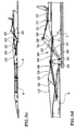
- the deployment kinematics takes place in three phases, the last of which is a combined phase.
- the tilting cylinders 21 are used, which has the effect of rotating the assembly by one block until the shoe 40 touches the ground by its edge. rounded attack 48.
- the second phase consists in the implementation of the pivoting cylinders 22. This is shown in FIG. 3 b .
- the action of the pivoting cylinders 22 has the effect of rotating the support pad 40 until its underside 43 presses completely on the ground.
- the third phase implements the deployment of the punch 23 and opening 24 jacks, causing complete deployment of the bridge as shown in FIGS. 3 c and 3 d .
- the deployment device will be described below more fully, by reporting its operation in the above phases 1 to 3.
- the tilting cylinders 21 are articulated at 14 on the point of attachment 17 located at the front part to the turret 12 and at 18 at the end 38 of the upper arm 31 of the respective bracket 30.
- the bracket 30 has a extension directed downwards comprising two auxiliary arms 32 and 33 joining at 29 to form a V, the brackets being perforated (openings 34 and 35).
- cylindrical tie rods 36, 37 and 70 connect the brackets respectively, on the one hand, to the lower end 29 to which the brackets are fixed at 16 in front of the chassis of the tank 1, the tie rod 36 being therefore aligned with the axis 11, on the other hand, in a middle part of the upper arm 31 between the openings 34 and 35, where the articulations of the jacks d opening 24 on the brackets 30 by means of two stirrups 27 arranged at the ends of the tie rod 37, and finally, at the rear part 38 of the upper arm 31, in the vicinity of the pivot axis 18 of the tilting cylinders 21.
- the leading edge 48 of rounded shape has in an intermediate region an opening 41 of substantially rectangular shape which has two legs 47 arranged so as to allow the articulation of the downstream ends 39 of the upper arms 31 of the brackets 30, which performs the articulation between the latter and the support pad 40 around the axis 49 (see in particular Figures 4 a and 4 b ).
- the pivot cylinders 22 are articulated at pad 40 at the end of stirrups 26 located on either side other of the punch 60 and between the brackets 30, at neighborhood of these.
- the stirrups 26 extend perpendicular to the bearing face 43 of the shoe 40, so that they end up in an upright position when the shoe 40 is placed on the ground by its bearing face 43.
- Phase 3 or combined phase implements the action of the punch 23 and opening 24 jacks, of which the operation is specified by the description below.
- the punch 60 is an elongate piece movable in rotation about an axis 65 relative to the shoe 40. It is fixed by two legs 61 which frame a projecting region 45 on either side of which ears 46 are arranged. The punch 60 is fixed to the shoe 40 between the hooks 44 for hooking the upstream part 5 of the bridge which form a pivot axis of the bridge, and therefore in a middle part of the shoe 40.
- the punch 60 is an elongated part in the general shape of a U and whose downstream end 63, which has a cone 67 for positioning the span 5 (see FIG. 4 b ), is housed in a region provided for this purpose of the upstream part 5 of the bridge.
- the punch cylinder 23, for its part, is articulated between on the one hand an axis 52 located at the end of a central stirrup 28 located between the stirrups 26, extending like them perpendicular to the bearing face 43 pads 40, and similar in shape to these, and on the other hand an axis 64 located near the end 63 of the punch 60.
- the punch cylinder is returned, the punch 60 comes into position stop on the central stirrup 28 belonging to the pad 40.
- the pivoting cylinders are retracted, the U-shaped plate 50 is taken between the stops 72 belonging to the punch 60 and the stops 71 belonging to the tie rod 70.
- the function of the punch 60 is to rotate the entire bridge which, in the case of a scissor bridge, is retained by the cables 15.
- the length of the cables 15 can be modified by the opening cylinders 24, which allows an adjustment of a scissor bridge according to the breach to be crossed.
- the cables 15 are stretched between, on the one hand, the end of an arm 55 secured to a frame 56 carried by the downstream element 6 of the bridge and situated in the vicinity of the axis of rotation 57 of the two elements 5 and 6 relative to each other and above them in the position shown in Figure 3b , and on the other hand one end of the U-shaped part 50.
- the pivoting of the bridge under the action of the jack punch 23 thus causes its opening, the degree of opening depending, in the case of a scissor bridge, on the length of the cables 15.
- the opening jacks 24 are articulated, each at one end, to the stirrup 27 and , at their other end, at 54, to the central branch of the U-shaped part 50, which has two arms 51 which are themselves articulated with the punch 60 around an axis 66 by means of two stirrups 62 arranged below the punch 60 and spaced laterally relative to each other.
- the stirrups 62 are located at a certain distance from the front end 63 so that, the device being in the folded position (FIGS. 1 a , 1 b , 4 a , 4 b ), the U-shaped part 50 is mainly located below the punch 60.
- phases 2 and 3 there is a rotation of the punch 60, of spans 5 and 6, of the plate U-shaped 50, punch cylinder 23 and cylinders opening 24.
- the position of the cylinder rod opening 24 allows adjustment of the cables 15, and therefore the degree of opening of the scissor bridge.
Landscapes
- Engineering & Computer Science (AREA)
- Architecture (AREA)
- Civil Engineering (AREA)
- Structural Engineering (AREA)
- Bridges Or Land Bridges (AREA)
Description
- la figure 1a représente en perspective un char portant un pont du type ciseau et équipé d'un dispositif de déploiement selon l'invention, la figure 1b étant une vue de côté de la figure 1a ;
- la figure 2 représente un char équipé d'un dispositif de déploiement selon l'invention, ce dispositif de déploiement étant en position repliée, par exemple suite à la pose du pont précité, le char représenté sur cette figure étant également équipé en partie arrière d'un dispositif de maintien réglable du pont ;
- les Figures 3a à 3d illustrent la pose d'un pont du type ciseau à l'aide du dispositif de déploiement selon la présente invention ;
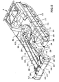
- les Figures 4a et 4b représentent deux vues en perspective l'une en trois quarts avant vue par le dessus et l'autre en trois quarts avant vue par le dessous du dispositif de déploiement selon l'invention
- deux équerres référencées 30 reliées entre elles par trois tirants 36, 37 et 70 et pivotant autour d'un axe 11 solidaire de la partie supérieure avant du châssis d'un véhicule porte-pont tel qu'un char 1 sous l'action de verins de basculement 21,
- un patin 40 d'appui au sol pivotant autour d'un axe 49 solidaire des équerres 30 et animé par deux vérins de pivotement 22,
- un poinçon 60 qui est une pièce de forme allongée pivotant autour d'un axe 65 solidaire du patin et qui est animé par un vérin de poinçon 23,
- une plaque en U 50 présentant deux branches 51 pivotant autour d'un axe 66 solidaire du poinçon 60, plaque de part et d'autre de laquelle sont montés premièrement deux câbles 15 assurant l'ouverture des deux parties respectivement amont 5 et aval 6 du pont 3 et deuxièmement deux vérins d'ouverture 24 assurant, dans le cas d'un pont ciseau, le réglage de l'ouverture du pont 3.
Claims (8)
- Dispositif de déploiement d'un pont comportant deux travures superposées (5,6) respectivement amont et aval qui sont déplaçables entre une position de transport dans laquelle les deux travures (5,6) sont repliées et superposées et sont portées par un véhicule (1), et une position de déploiement dans laquelle les deux travures (5,6) sont disposées sensiblement dans le prolongement l'une de l'autre pour former un pont déployé, ledit dispositif comportant un moyen de basculement (30) pivotant autour d'au moins un premier axe (11) solidaire dudit véhicule (1) sous l'action d'au moins un vérin de basculement (21), l'élément de basculement (30) supportant le pont pendant au moins une phase préliminaire de son déploiement, un patin (40) d'appui au sol, présentant une face d'appui (43) et pivotant autour d'un deuxième axe (49) par rapport à l'élément de basculement (30) sous l'action d'au moins un vérin de pivotement (22), l'extrémité amont de ladite partie amont du pont étant articulée autour d'un troisième axe (44) porté par le patin d'appui (40), et un poinçon (60) de pivotement du pont actionné par au moins un vérin de poinçon (23) et articulé à une extrémité amont autour d'un quatrième axe (65) solidaire du patin d'appui (40) et présentant une extrémité aval (67) logée dans ladite travure amont (5) du pont, le moyen de basculement (30) comportant deux équerres (30) qui sont espacées latéralement l'une de l'autre et qui sont articulées chacune en une région d'articulation (16) située sur ledit premier axe (11), et deux vérins de basculement (21) étant disposés parallèlement l'un à l'autre et articulés à leur première extrémité sur une partie supérieure du véhicule (12) et à leur deuxième extrémité à une partie supérieure (31) de l'équerre (30) et à l'arrière (38) de celle-ci, caractérisé en ce qu'il comporte une plaque (50) pivotant autour d'un axe (66) solidaire du poinçon (60), de part et d'autre de laquelle sont montés deux câbles (15) d'ouverture du pont et en ce que, en position repliée du vérin de pivotement (22), la plaque (50) est prise entre une butée (71) portée par un élément de renfort mécanique (70) reliant mécaniquement les deux équerres (30) et une butée (72) du poinçon (66).
- Dispositif selon la revendication 1, caractérisé en ce que les équerres (30) comportent chacune un bras supérieur (31) à l'extrémité arrière (38) duquel s'articule la deuxième extrémité du vérin de basculement (21) correspondant et à l'extrémité avant (39) duquel est disposé le deuxième axe, et en ce qu'elles comportent un prolongement (32, 33) s'étendant depuis le bras supérieur jusqu'à ladite région d'articulation (16).
- Dispositif selon la revendication 1 ou 2, caractérisé en ce que le vérin de poinçon (23) est logé entre les deux équerres (30) et présente une première extrémité articulée au patin d'appui (40) autour d'un cinquième axe (52) situé dans une région centrale du patin d'appui (40) et une deuxième extrémité articulée autour d'un sixième axe (64) porté par le poinçon (60) et situé au voisinage de l'extrémité aval du poinçon (60).
- Dispositif selon la revendication 3, caractérisé en ce que le cinquième axe (52) est disposé à l'extrémité d'un étrier central (28) s'étendant perpendiculairement à la face d'appui (43) du patin (40).
- Dispositif selon une des revendications précédentes, caractérisé en ce que, dans la position de transport, le patin (40) est dans une position relevée permettant de dégager la vue vers l'avant du véhicule.
- Dispositif selon une des revendications précédentes, caractérisé en ce que ledit câble (15) de déploiement du pont (5,6) est actionné par au moins un vérin d'ouverture (24).
- Dispositif selon une des revendications précédentes, caractérisé en ce qu'il comporte deux vérins de pivotement (22) articulés au patin d'appui (40) à l'extrémité d'étriers (26) disposés au niveau des équerres (30) et de part et d'autre du poinçon (60), lesdits étriers (26) s'étendant perpendiculairement à la face d'appui (43) du patin d'appui (40).
- Dispositif selon une des revendications précédentes, caractérisé en ce qu'il comporte un dispositif tendeur de câbles de déploiement du pont actionné par deux vérins d'ouverture (24) articulés, à une extrémité amont, à la partie centrale d'un bras supérieur (31) des équerres (30).
Applications Claiming Priority (2)
| Application Number | Priority Date | Filing Date | Title |
|---|---|---|---|
| FR9502694 | 1995-03-08 | ||
| FR9502694A FR2731447B1 (fr) | 1995-03-08 | 1995-03-08 | Dispositif de deploiement d'un pont a deux travures superposees |
Publications (2)
| Publication Number | Publication Date |
|---|---|
| EP0731219A1 EP0731219A1 (fr) | 1996-09-11 |
| EP0731219B1 true EP0731219B1 (fr) | 2001-11-07 |
Family
ID=9476855
Family Applications (1)
| Application Number | Title | Priority Date | Filing Date |
|---|---|---|---|
| EP19960400373 Expired - Lifetime EP0731219B1 (fr) | 1995-03-08 | 1996-02-23 | Dispositif de déploiement d'un pont à deux travures superposées |
Country Status (3)
| Country | Link |
|---|---|
| EP (1) | EP0731219B1 (fr) |
| DE (1) | DE69616617T2 (fr) |
| FR (1) | FR2731447B1 (fr) |
Families Citing this family (6)
| Publication number | Priority date | Publication date | Assignee | Title |
|---|---|---|---|---|
| FR2834524B1 (fr) | 2002-01-07 | 2004-10-22 | Giat Ind Sa | Systeme de pose d'un pont |
| EP1585863A1 (fr) | 2003-01-22 | 2005-10-19 | Giat Industries | Systeme de pose d un pont |
| DE102004049969B8 (de) * | 2004-10-14 | 2006-03-23 | Military Mobile Bridges Gmbh | Modulare Scherenbrücke sowie Verlegeeinrichtung und Verfahren zum Verlegen zerlegbarer Brücken |
| DE102010061102A1 (de) * | 2010-12-08 | 2012-06-14 | Krauss-Maffei Wegmann Gmbh & Co. Kg | Verlegeeinrichtung zur Anordnung an Brückenverlegefahrzeugen und Brückenverlegefahrzeug |
| DE102014008178A1 (de) | 2014-06-10 | 2015-12-17 | General Dynamics European Land Systems-Germany Gmbh | Transportierbare faltbare Brücke |
| DE102020129687A1 (de) * | 2020-11-11 | 2022-05-12 | Krauss-Maffei Wegmann Gmbh & Co. Kg | Brückenverlegefahrzeug |
Family Cites Families (2)
| Publication number | Priority date | Publication date | Assignee | Title |
|---|---|---|---|---|
| DE1658367A1 (de) * | 1965-01-19 | 1970-10-22 | Jean Vaillant | Transportfahrzeug fuer eine transportable Bruecke |
| GB8821298D0 (en) * | 1988-09-12 | 1988-10-12 | Secr Defence | Folding transportable bridge |
-
1995
- 1995-03-08 FR FR9502694A patent/FR2731447B1/fr not_active Expired - Fee Related
-
1996
- 1996-02-23 DE DE1996616617 patent/DE69616617T2/de not_active Expired - Fee Related
- 1996-02-23 EP EP19960400373 patent/EP0731219B1/fr not_active Expired - Lifetime
Also Published As
| Publication number | Publication date |
|---|---|
| FR2731447A1 (fr) | 1996-09-13 |
| DE69616617T2 (de) | 2002-08-01 |
| EP0731219A1 (fr) | 1996-09-11 |
| DE69616617D1 (de) | 2001-12-13 |
| FR2731447B1 (fr) | 1997-06-06 |
Similar Documents
| Publication | Publication Date | Title |
|---|---|---|
| FR2652491A1 (fr) | Siege. | |
| FR2732000A1 (fr) | Grue a montage automatise avec fleche repliable sur elle-meme | |
| FR2659186A1 (fr) | Dispositif de travail agricole destine a etre monte a l'avant d'un tracteur. | |
| EP0280626B1 (fr) | Système de déploiement et de dépose d'une travure de franchissement d'un obstacle à partir d'un véhicule tel qu'un engin blindé du génie | |
| EP0051100A1 (fr) | Arceau de sécurité pivotant pour véhicule, notamment pour tracteur porte-outils | |
| FR2790252A1 (fr) | Dispositif de depliage ou repliage simultane d'elements de pointe de fleche de grue | |
| EP0731219A1 (fr) | Dispositif de déploiement d'un pont à deux travures superposées | |
| FR2940745A1 (fr) | Ensemble a vehicule tracteur et machine de traitement du sol, telle qu'une machine de debroussaillage-broyage de vegetaux | |
| EP0100926A1 (fr) | Véhicule de manutention à bras orientable et châssis stabilisateur incorporé | |
| FR2464624A1 (fr) | Mecanisme de support d'un instrument sur un tracteur ou analogue | |
| EP0733583B1 (fr) | Grue à montage automatisé avec flèche repliable latéralement | |
| FR2577302A1 (fr) | Stabilisateur a inclinaison variable et semelle escamotable. | |
| FR2539124A3 (fr) | Dispositif de levage et de basculement pour l'entretien et la reparation de vehicules | |
| FR2679732A1 (fr) | Dispositif groupeur de balles de fourrage cylindriques. | |
| FR2527581A1 (fr) | Plate-forme d'acces | |
| FR2627441A1 (fr) | Potence de chargement/dechargement a bras retractable, et vehicule la comportant | |
| FR2733951A1 (fr) | Dispositif de support de charge, formant notamment galerie porte-bagages pour toit de vehicule automobile | |
| FR2466427A1 (fr) | Grue, notamment grue de grandes dimensions | |
| FR2695843A1 (fr) | Support universel de peinture, notamment pour éléments de carrosserie automobile. | |
| FR2480626A1 (fr) | Dispositif de support orientable pour rampe d'arrosage d'un vehicule de nettoyage de la voirie | |
| FR2541559A1 (fr) | Semoir a chassis repliable lateralement | |
| EP1445179A1 (fr) | Remorque pour le transport d'engins agricoles | |
| FR2522636A1 (fr) | Chargeur frontal pour tracteur | |
| FR2850944A1 (fr) | Remorque pour le transport d'engins agricoles | |
| FR2718769A1 (fr) | Ensemble compact de deux bras articulés, dont l'extrémité libre est équipée d'un porte équipement, destiné à des véhicules de manutention, et terrassement. |
Legal Events
| Date | Code | Title | Description |
|---|---|---|---|
| PUAI | Public reference made under article 153(3) epc to a published international application that has entered the european phase |
Free format text: ORIGINAL CODE: 0009012 |
|
| AK | Designated contracting states |
Kind code of ref document: A1 Designated state(s): DE GB |
|
| 17P | Request for examination filed |
Effective date: 19961023 |
|
| 17Q | First examination report despatched |
Effective date: 19991104 |
|
| GRAG | Despatch of communication of intention to grant |
Free format text: ORIGINAL CODE: EPIDOS AGRA |
|
| GRAG | Despatch of communication of intention to grant |
Free format text: ORIGINAL CODE: EPIDOS AGRA |
|
| GRAH | Despatch of communication of intention to grant a patent |
Free format text: ORIGINAL CODE: EPIDOS IGRA |
|
| GRAH | Despatch of communication of intention to grant a patent |
Free format text: ORIGINAL CODE: EPIDOS IGRA |
|
| GRAA | (expected) grant |
Free format text: ORIGINAL CODE: 0009210 |
|
| AK | Designated contracting states |
Kind code of ref document: B1 Designated state(s): DE GB |
|
| GBT | Gb: translation of ep patent filed (gb section 77(6)(a)/1977) |
Effective date: 20011107 |
|
| REF | Corresponds to: |
Ref document number: 69616617 Country of ref document: DE Date of ref document: 20011213 |
|
| REG | Reference to a national code |
Ref country code: GB Ref legal event code: IF02 |
|
| PLBE | No opposition filed within time limit |
Free format text: ORIGINAL CODE: 0009261 |
|
| STAA | Information on the status of an ep patent application or granted ep patent |
Free format text: STATUS: NO OPPOSITION FILED WITHIN TIME LIMIT |
|
| 26N | No opposition filed | ||
| PGFP | Annual fee paid to national office [announced via postgrant information from national office to epo] |
Ref country code: GB Payment date: 20070130 Year of fee payment: 12 |
|
| PGFP | Annual fee paid to national office [announced via postgrant information from national office to epo] |
Ref country code: DE Payment date: 20070131 Year of fee payment: 12 |
|
| GBPC | Gb: european patent ceased through non-payment of renewal fee |
Effective date: 20080223 |
|
| PG25 | Lapsed in a contracting state [announced via postgrant information from national office to epo] |
Ref country code: DE Free format text: LAPSE BECAUSE OF NON-PAYMENT OF DUE FEES Effective date: 20080902 |
|
| PG25 | Lapsed in a contracting state [announced via postgrant information from national office to epo] |
Ref country code: GB Free format text: LAPSE BECAUSE OF NON-PAYMENT OF DUE FEES Effective date: 20080223 |