EP0730552B1 - Behälter mit einer verriegelbaren deckelanordnung - Google Patents
Behälter mit einer verriegelbaren deckelanordnung Download PDFInfo
- Publication number
- EP0730552B1 EP0730552B1 EP95903073A EP95903073A EP0730552B1 EP 0730552 B1 EP0730552 B1 EP 0730552B1 EP 95903073 A EP95903073 A EP 95903073A EP 95903073 A EP95903073 A EP 95903073A EP 0730552 B1 EP0730552 B1 EP 0730552B1
- Authority
- EP
- European Patent Office
- Prior art keywords
- cover member
- side walls
- container
- tray
- wall
- Prior art date
- Legal status (The legal status is an assumption and is not a legal conclusion. Google has not performed a legal analysis and makes no representation as to the accuracy of the status listed.)
- Expired - Lifetime
Links
- 210000002105 tongue Anatomy 0.000 claims description 18
- 239000000463 material Substances 0.000 claims description 7
- 239000011087 paperboard Substances 0.000 claims description 7
- 239000000853 adhesive Substances 0.000 claims description 4
- 230000001070 adhesive effect Effects 0.000 claims description 4
- 230000013011 mating Effects 0.000 claims description 2
- 238000004026 adhesive bonding Methods 0.000 description 1
- 238000011161 development Methods 0.000 description 1
- 230000018109 developmental process Effects 0.000 description 1
- 230000000694 effects Effects 0.000 description 1
- 238000004519 manufacturing process Methods 0.000 description 1
- 238000012856 packing Methods 0.000 description 1
Images


Classifications
-
- B—PERFORMING OPERATIONS; TRANSPORTING
- B65—CONVEYING; PACKING; STORING; HANDLING THIN OR FILAMENTARY MATERIAL
- B65D—CONTAINERS FOR STORAGE OR TRANSPORT OF ARTICLES OR MATERIALS, e.g. BAGS, BARRELS, BOTTLES, BOXES, CANS, CARTONS, CRATES, DRUMS, JARS, TANKS, HOPPERS, FORWARDING CONTAINERS; ACCESSORIES, CLOSURES, OR FITTINGS THEREFOR; PACKAGING ELEMENTS; PACKAGES
- B65D5/00—Rigid or semi-rigid containers of polygonal cross-section, e.g. boxes, cartons or trays, formed by folding or erecting one or more blanks made of paper
- B65D5/42—Details of containers or of foldable or erectable container blanks
- B65D5/64—Lids
- B65D5/68—Telescope flanged lids
- B65D5/685—Telescope flanged lids having an inwardly or upwardly extending tab on the lid side wall cooperating with a tab on, or an opening in, the container side wall
Definitions
- This invention relates to a container, especially a food container, having an interlocking cover arrangement, the container having a tray member including a plane bottom wall and four tray member side walls upstanding from the latter to form a box-like structure open at the top, the tray member side walls each including an outer flange element, the container also has a cover member including a plane top wall and four cover member side walls depending from said top wall to form a box-like structure open at the bottom, each of the opposite side walls of said cover member side walls having at least one locking tongue which is situated on the inside of its respective side wall and which is inwardly biassed, each locking tongue presenting an upwardly facing abutment for engagement with a corresponding downwardly facing abutment on said tray member.
- the object of the present invention is, therefore, to provide a container of the aforementioned kind, which provides a stronger and safer interlocking between the tray and cover members. This object will be achieved by a container according to the invention and having the characteristics set forth in Claim 1.
- the outer flange elements consist of brims projecting outwardly from the periphery of the tray member in a direction substantially parallel to the plane of the bottom wall of the tray member, said brims each having a bottom surface forming said downwardly facing abutment, and said brims each having a top surface forming an abutment surface for engagement with said top wall of the cover member, an opposed pair of the brims having apertures for mating engagement with each of said locking tongues by snap-action.
- Fig. 1 is a perspective view of a tray member according to the invention.
- Figs. 2 - 5 illustrate four sequential stages for the manufacture of a tray member according to the invention.
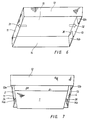
- Figs. 6 - 7 illustrate in sequence two operational stages in interlocking a tray member and a cover member according to the invention.
- Fig. 1 shows a rectangular tray member 1 of a plane, stiff material, for instance a paperboard material.
- the tray member has a plane bottom wall 1a and four side walls 1b-e up-standing from the bottom wall 1a to form a box-like structure open at the top.
- Each tray member side wall 1b-e has an outer flange in the form of a brim 2, 3, 4, and 5, respectively, projecting outwardly from the periphery of the tray member in a direction substantially parallel to the plane of the bottom wall 1a of the tray member.
- the tray member may be either right-angled or conical in order to enable a piling of several tray members into one another.
- the tray member may also be foldable, for instance of the type described in Swedish patent specification Number 8405157-2.
- Each of the two opposed brim portions 2 and 4 see Fig. 1, has two through, oblique apertures 6, 7 and 8, 9, respectively, which improve the interlocking function, as will be explained below.
- Fig. 2 shows a cut out plane blank of a plastic treated paperboard or the like, which, after folding and glueing, will form the cover member illustrated in Figs. 3 - 5.
- the cover member has, see Fig. 2, a plane top wall 10 and four rectangular cover member side walls 11 - 14 foldable downwards at approximately right angles via fold lines 15 - 18 such that the four side walls 11 - 14 will depend from the top wall 10 to form a box-like structure open at the bottom.
- the side walls 11 - 14 have been cut out in a manner such that the box-like structure will converge conically downwardly.
- the two longer side walls 12 and 14 have, at their ends, an extension portion 12a, 12b and 14a, 14b, respectively, which can, via fold lines 19 - 22, be folded inwardly at approximately right angles to the longer side walls 12 and 14, respectively, and be fastened, for instance by adhesive 23 - 26, to an adjacent short side wall 11 and 13, respectively, see Fig. 3.
- Each end of the short side walls 11 and 13 has a fold line 27 - 30, respectively, extending in about 45 degrees from a respective one of the corners of the top wall 10.
- These fold lines 27 - 30 enable an infolding of the short side walls 11 and 13 towards the top wall 10, see Fig. 4, to permit the cover member to be collapsed into a flattened condition, see Fig. 5, which condition the cover member will have during transport prior to packing of the tray member.
- the adhesive 23 - 26 has been applied only to a triangular area, see Fig. 2, at the end of each short side wall 11 and 13, which area is located outside the respective fold line 27 - 30, thus causing only a corresponding triangular area of the extension portions 12a-b, 14a-b, to be glued to an associated one of short side walls 11 and 13.
- the outermost area of the extension portions 12a-b and 14a-b, respectively will remain free from the adhesive and will not be glued to its associated short side wall 11 and 13, respectively.
- This will accomplish the special effect that the non-glued areas of the extension portions 12a-b and 14a-b, respectively, will move relative to its associate short side wall, when this is being infolded towards the top wall 10, as is seen in Fig. 4.
- the nonglued areas of the extension portions 12a-b and 14a-b, respectively, can, thereby, be used as a kind of locking tongues, which can be said to be indirectly biassed by said inherent springiness of the paperboard material of the short side walls of the tray member.
- the function of these locking tongues will be apparent from the description below by reference to Figs. 6 and 7.
- Fig. 6 is a perspective view, as seen obliquely from beneath, of a cover member according to the invention
- Fig. 7 is a perspective view, as seen obliquely from beneath, of a tray member 1 with a cover member telescoped over the tray member.
- the effective locking depth provided by the apertures 6 - 9 is in fact greater than the thickness of the brims 2 - 5. Namely, in practice, the brims 2 - 5 will not be oriented exactly in parallel with the top wall 10 of the cover member, but will incline a few degrees, such that the locking tongues, when moving through the apertures, will move a certain distance past the apertures, which will cause a still stronger interlocking between the tray and cover members.
- the length of the extension portions 12a-b and 14a-b and the configuration, location and angle of the apertures 6 - 9 is dimensioned such that the non-glued areas of the extension portions (i.e. the "locking tongues") or their heels or hooks 33 - 36, if such are present, will obtain the same direction and location as the apertures in order to ensure that the locking tongues will get an optimal engagement with its associated aperture.
Landscapes
- Engineering & Computer Science (AREA)
- Mechanical Engineering (AREA)
- Cartons (AREA)
- Closures For Containers (AREA)
- Laying Of Electric Cables Or Lines Outside (AREA)
Claims (5)
- Ein Behälter, insbesondere ein Lebensmittelbehälter, der eine Ineinanderverriegelungs-Deckelanordnung besitzt, wobei der Behälter ein Kastenelement (1) aufweist, das eine ebene Bodenwand (1a) und vier Kastenelement-Seitenwände (1b-e) umfaßt, die von ihr aus aufrecht stehen, um eine kastenartige Struktur zu bilden, die oben offen ist, wobei die Kastenelement-Seitenwände (1b-e) jeweils ein äußeres Flanschelement (2-5) umfassen, und wobei der Behälter weiter ein Deckelelement aufweist, das eine ebene obere Wand (10) und vier Deckelelement-Seitenwände (11-14) umfaßt, die von derselben abwärts gerichtet sind, um eine kastenartige Struktur zu bilden, die unten offen ist, wobei zwei einander gegenüberliegende Seitenwände (11, 13) der genannten Deckelelement-Seitenwände mindestens eine Verriegelungszunge (12a-b, 14a-b) besitzen, welche auf der Innenseite ihrer jeweiligen Seitenwand plaziert ist und nach innen hin schräggestellt ist, wobei jede Verriegelungszunge (12a-b, 14a-b) einen nach oben hin weisenden Anschlag für den Anschluß mit einem entsprechenden, nach unten weisenden Anschlag auf dem Kastenelement besitzt,
dadurch gekennzeichnet, daß
das äußere Flanschelement aus Krempen (2-5) besteht, die von der Peripherie des Kastenelementes (1) aus in eine Richtung vorstehen, die im wesentlichen parallel zu der Ebene der Bodenwand (1a) des Kastenelementes verläuft, wobei die genannten Krempen (2-5) jeweils eine untere Oberfläche aufweisen, die den genannten, nach unten weisenden Anschlag bildet, und wobei die genannten Krempen (2-5) jeweils eine obere Oberfläche aufweisen, die eine Anschlagoberfläche für den Anschluß mit der genannten oberen Wand (10) des Deckelelementes bilden, wobei ein einander gegenüberliegendes Paar (2, 4) der Krempen Öffnungen (6-9) zum ineinandergreifenden Verbinden mit jeder der genannten Verriegelungszungen (12a-b, 14a-b) durch Schnappbewegung aufweist. - Ein Behälter nach Anspruch 1, dadurch gekennzeichnet, daß das Deckelelement aus einem Papierkartonmaterial gebildet ist und daß jede der genannten, einander gegenüberliegenden Seitenwände (11, 13) des Dekkelelementes zwei Faltlinien (jeweils 27, 28 und 29, 30) aufweisen, die ein Falten der genannten, einander gegenüberliegenden Seitenwände (11, 13) nach innen zur oberen Wand (10) des Deckelelements hin ermöglichen, um in einen abgeflachten Zustand zu kollabieren, wobei die inhärente Federungsfähigkeit des Papierkartonmaterials danach strebt, im aufgerichteten Zustand des Deckelelementes die genannten, einander gegenüberliegenden Seitenwände (11, 13) in Richtung auf die genannte obere Wand (10) des Deckelelementes hin einzufalten und um somit die genannte Schrägstellung der genannten Verriegelungszungen (12a-b, 14a-b) zu erzeugen.
- Ein Behälter nach Anspruch 2, dadurch gekennzeichnet, daß jede der genannten, einander entgegengesetzten Seitenwände (11, 13) zwei Verriegelungszungen (12a-b, 14a-b) der erwähnten Art besitzt, von denen jede einen ersten Zungenabschnitt und einen zweiten Zungenabschnitt aufweist, der an der entgegengesetzten Seite der genannten Faltlinie (27-30) plaziert ist, aber nicht an der genannten Deckelelement-Seitenwand befestigt ist, derart, daß der zweite Zungenabschnitt sich relativ zu der genannten Deckelelement-Seitenwand bewegt, wenn diese von der oberen Wand (10) des Deckelelementes aus nach oben bewegt oder zu ihr hin nach innen gefaltet wird.
- Ein Behälter nach Anspruch 3, dadurch gekennzeichnet, daß jede der Deckelelement-Seitenwände (12, 14), welche zwischen den genannten, einander gegenüberliegenden Deckelelement-Seitenwänden (11, 13) plaziert sind, einen Erweiterungsabschnitt (12a-b, 14a-b) aufweist, der nach innen hin zu den genannten, einander gegenüberliegenden Wänden (11, 13) faltbar ist und die die genannten Verriegelungszungen bildet.
- Ein Behälter nach Anspruch 1, dadurch gekennzeichnet, daß jede der Verriegelungszungen (12a-b, 14a-b) einen Haken (33-36) besitzt, der angepaßt ist, um ineinandergreifend die Anschlußverbindung mit einer entsprechenden Öffnung der genannten Öffnungen (6-9) zu bewirken.
Applications Claiming Priority (3)
| Application Number | Priority Date | Filing Date | Title |
|---|---|---|---|
| SE9303949 | 1993-11-29 | ||
| SE9303949A SE507781C2 (sv) | 1993-11-29 | 1993-11-29 | Med låsbart lock försett tråg |
| PCT/SE1994/001129 WO1995014615A1 (en) | 1993-11-29 | 1994-11-24 | Container having an interlocking cover arrangement |
Publications (2)
| Publication Number | Publication Date |
|---|---|
| EP0730552A1 EP0730552A1 (de) | 1996-09-11 |
| EP0730552B1 true EP0730552B1 (de) | 1998-06-10 |
Family
ID=20391916
Family Applications (1)
| Application Number | Title | Priority Date | Filing Date |
|---|---|---|---|
| EP95903073A Expired - Lifetime EP0730552B1 (de) | 1993-11-29 | 1994-11-24 | Behälter mit einer verriegelbaren deckelanordnung |
Country Status (6)
| Country | Link |
|---|---|
| EP (1) | EP0730552B1 (de) |
| DE (1) | DE69411033T2 (de) |
| DK (1) | DK0730552T3 (de) |
| NO (1) | NO308163B1 (de) |
| SE (1) | SE507781C2 (de) |
| WO (1) | WO1995014615A1 (de) |
Families Citing this family (1)
| Publication number | Priority date | Publication date | Assignee | Title |
|---|---|---|---|---|
| DE202007012019U1 (de) | 2007-08-28 | 2008-02-21 | Penzkofer, Klaus | Abgassystem für Kraftfahrzeuge mit Verbrennungsmotoren |
Family Cites Families (6)
| Publication number | Priority date | Publication date | Assignee | Title |
|---|---|---|---|---|
| US2961144A (en) * | 1958-07-21 | 1960-11-22 | American Box Board Co | Pilfer-proof box |
| SE395865B (sv) * | 1975-04-03 | 1977-08-29 | Sprinter Pack Ab | Kartongtrag med lock |
| US4114798A (en) * | 1977-10-28 | 1978-09-19 | Container Corporation Of America | Interlocking cover and tray |
| US4531669A (en) * | 1983-07-06 | 1985-07-30 | Westvaco Corporation | Interlock between telescoping cover and tray |
| FR2564428B3 (fr) * | 1984-05-16 | 1986-05-16 | Sauterot Drac | Boite en carton, de forme parallelepipedique pouvant etre stockee a plat |
| DE3828294A1 (de) * | 1987-08-20 | 1989-07-06 | Orbke Ilse | Deckel aus karton oder aehnlichem material zum allseitigen verschliessen von menueschalen oder aehnliche behaeltnisse |
-
1993
- 1993-11-29 SE SE9303949A patent/SE507781C2/sv not_active IP Right Cessation
-
1994
- 1994-11-24 WO PCT/SE1994/001129 patent/WO1995014615A1/en not_active Ceased
- 1994-11-24 EP EP95903073A patent/EP0730552B1/de not_active Expired - Lifetime
- 1994-11-24 DE DE69411033T patent/DE69411033T2/de not_active Expired - Fee Related
- 1994-11-24 DK DK95903073T patent/DK0730552T3/da active
-
1996
- 1996-05-24 NO NO962140A patent/NO308163B1/no unknown
Also Published As
| Publication number | Publication date |
|---|---|
| WO1995014615A1 (en) | 1995-06-01 |
| SE9303949D0 (sv) | 1993-11-29 |
| DE69411033D1 (de) | 1998-07-16 |
| DE69411033T2 (de) | 1998-11-19 |
| NO308163B1 (no) | 2000-08-07 |
| SE507781C2 (sv) | 1998-07-13 |
| EP0730552A1 (de) | 1996-09-11 |
| DK0730552T3 (da) | 1998-10-12 |
| NO962140L (no) | 1996-05-24 |
| NO962140D0 (no) | 1996-05-24 |
| SE9303949L (sv) | 1995-05-30 |
Similar Documents
| Publication | Publication Date | Title |
|---|---|---|
| US4793546A (en) | Box | |
| US3343660A (en) | Box closure | |
| US5458270A (en) | Foldable liquid container for preventing leakage | |
| US5588585A (en) | Automatic set-up carton with corner posts | |
| US4832199A (en) | Auto lock display tray | |
| US6948617B2 (en) | Stackable container with support flanges | |
| US4389013A (en) | Container having a self-locking lid | |
| US3494536A (en) | Self-forming closed carton | |
| US5402929A (en) | Container tray-cover corner closure arrangement | |
| US4511080A (en) | Interlocking end closure flaps on collapsible eight-sided receptacle | |
| EP0575183B1 (de) | Zusammenlegbarer Palettenbehälter | |
| US4648549A (en) | Self-locking container | |
| US4702409A (en) | Tray with reinforced corners | |
| US7467743B1 (en) | Container having self-locking structure to provide added stability | |
| US4767051A (en) | Knockdown carton with pre-glued bottom | |
| US5573175A (en) | Octagonal container with lock bottom | |
| US2443431A (en) | Container structures for liquid, semiliquid, and freely flowable products, especially food products to be frozen | |
| WO1987002008A1 (en) | Stackable tapering tray | |
| US4898321A (en) | Case and pallet systems | |
| US4240576A (en) | Distribution package | |
| US3272421A (en) | Self-locking carton | |
| US6220508B1 (en) | Quick-lock open-bottom bulk box with easy set-up feature | |
| EP0730552B1 (de) | Behälter mit einer verriegelbaren deckelanordnung | |
| US4189088A (en) | Container with interlocking corners | |
| US6651873B2 (en) | Container with bag cuff grab means |
Legal Events
| Date | Code | Title | Description |
|---|---|---|---|
| PUAI | Public reference made under article 153(3) epc to a published international application that has entered the european phase |
Free format text: ORIGINAL CODE: 0009012 |
|
| 17P | Request for examination filed |
Effective date: 19960618 |
|
| AK | Designated contracting states |
Kind code of ref document: A1 Designated state(s): DE DK FR GB IT NL |
|
| 17Q | First examination report despatched |
Effective date: 19970402 |
|
| GRAG | Despatch of communication of intention to grant |
Free format text: ORIGINAL CODE: EPIDOS AGRA |
|
| GRAG | Despatch of communication of intention to grant |
Free format text: ORIGINAL CODE: EPIDOS AGRA |
|
| GRAH | Despatch of communication of intention to grant a patent |
Free format text: ORIGINAL CODE: EPIDOS IGRA |
|
| GRAH | Despatch of communication of intention to grant a patent |
Free format text: ORIGINAL CODE: EPIDOS IGRA |
|
| GRAA | (expected) grant |
Free format text: ORIGINAL CODE: 0009210 |
|
| AK | Designated contracting states |
Kind code of ref document: B1 Designated state(s): DE DK FR GB IT NL |
|
| PG25 | Lapsed in a contracting state [announced via postgrant information from national office to epo] |
Ref country code: IT Free format text: LAPSE BECAUSE OF FAILURE TO SUBMIT A TRANSLATION OF THE DESCRIPTION OR TO PAY THE FEE WITHIN THE PRESCRIBED TIME-LIMIT;WARNING: LAPSES OF ITALIAN PATENTS WITH EFFECTIVE DATE BEFORE 2007 MAY HAVE OCCURRED AT ANY TIME BEFORE 2007. THE CORRECT EFFECTIVE DATE MAY BE DIFFERENT FROM THE ONE RECORDED. Effective date: 19980610 |
|
| ET | Fr: translation filed | ||
| REF | Corresponds to: |
Ref document number: 69411033 Country of ref document: DE Date of ref document: 19980716 |
|
| REG | Reference to a national code |
Ref country code: DK Ref legal event code: T3 |
|
| PLBE | No opposition filed within time limit |
Free format text: ORIGINAL CODE: 0009261 |
|
| STAA | Information on the status of an ep patent application or granted ep patent |
Free format text: STATUS: NO OPPOSITION FILED WITHIN TIME LIMIT |
|
| 26N | No opposition filed | ||
| PGFP | Annual fee paid to national office [announced via postgrant information from national office to epo] |
Ref country code: FR Payment date: 20011129 Year of fee payment: 8 |
|
| PGFP | Annual fee paid to national office [announced via postgrant information from national office to epo] |
Ref country code: NL Payment date: 20011130 Year of fee payment: 8 |
|
| PGFP | Annual fee paid to national office [announced via postgrant information from national office to epo] |
Ref country code: DE Payment date: 20011227 Year of fee payment: 8 |
|
| REG | Reference to a national code |
Ref country code: GB Ref legal event code: IF02 |
|
| PGFP | Annual fee paid to national office [announced via postgrant information from national office to epo] |
Ref country code: GB Payment date: 20021122 Year of fee payment: 9 |
|
| PGFP | Annual fee paid to national office [announced via postgrant information from national office to epo] |
Ref country code: DK Payment date: 20021125 Year of fee payment: 9 |
|
| PG25 | Lapsed in a contracting state [announced via postgrant information from national office to epo] |
Ref country code: NL Free format text: LAPSE BECAUSE OF NON-PAYMENT OF DUE FEES Effective date: 20030601 |
|
| PG25 | Lapsed in a contracting state [announced via postgrant information from national office to epo] |
Ref country code: DE Free format text: LAPSE BECAUSE OF NON-PAYMENT OF DUE FEES Effective date: 20030603 |
|
| PG25 | Lapsed in a contracting state [announced via postgrant information from national office to epo] |
Ref country code: FR Free format text: LAPSE BECAUSE OF NON-PAYMENT OF DUE FEES Effective date: 20030731 |
|
| NLV4 | Nl: lapsed or anulled due to non-payment of the annual fee |
Effective date: 20030601 |
|
| REG | Reference to a national code |
Ref country code: FR Ref legal event code: ST |
|
| PG25 | Lapsed in a contracting state [announced via postgrant information from national office to epo] |
Ref country code: GB Free format text: LAPSE BECAUSE OF NON-PAYMENT OF DUE FEES Effective date: 20031124 |
|
| PG25 | Lapsed in a contracting state [announced via postgrant information from national office to epo] |
Ref country code: DK Free format text: LAPSE BECAUSE OF NON-PAYMENT OF DUE FEES Effective date: 20031201 |
|
| REG | Reference to a national code |
Ref country code: DK Ref legal event code: EBP |
|
| GBPC | Gb: european patent ceased through non-payment of renewal fee |
Effective date: 20031124 |