EP0730536B1 - Pre-fitted carrier unit for the functional parts of a safety belt system - Google Patents
Pre-fitted carrier unit for the functional parts of a safety belt system Download PDFInfo
- Publication number
- EP0730536B1 EP0730536B1 EP95903095A EP95903095A EP0730536B1 EP 0730536 B1 EP0730536 B1 EP 0730536B1 EP 95903095 A EP95903095 A EP 95903095A EP 95903095 A EP95903095 A EP 95903095A EP 0730536 B1 EP0730536 B1 EP 0730536B1
- Authority
- EP
- European Patent Office
- Prior art keywords
- carrier unit
- anchorage
- height adjustment
- belt retractor
- adjustment mechanism
- Prior art date
- Legal status (The legal status is an assumption and is not a legal conclusion. Google has not performed a legal analysis and makes no representation as to the accuracy of the status listed.)
- Expired - Lifetime
Links
- 230000007246 mechanism Effects 0.000 claims description 100
- 238000006073 displacement reaction Methods 0.000 claims description 30
- 230000001419 dependent effect Effects 0.000 claims 1
- 238000010276 construction Methods 0.000 description 7
- 238000004519 manufacturing process Methods 0.000 description 3
- 239000002184 metal Substances 0.000 description 1
- 230000004048 modification Effects 0.000 description 1
- 238000012986 modification Methods 0.000 description 1
- 230000000717 retained effect Effects 0.000 description 1
Images



Classifications
-
- B—PERFORMING OPERATIONS; TRANSPORTING
- B60—VEHICLES IN GENERAL
- B60R—VEHICLES, VEHICLE FITTINGS, OR VEHICLE PARTS, NOT OTHERWISE PROVIDED FOR
- B60R22/00—Safety belts or body harnesses in vehicles
- B60R22/18—Anchoring devices
- B60R22/24—Anchoring devices secured to the side, door, or roof of the vehicle
-
- B—PERFORMING OPERATIONS; TRANSPORTING
- B60—VEHICLES IN GENERAL
- B60R—VEHICLES, VEHICLE FITTINGS, OR VEHICLE PARTS, NOT OTHERWISE PROVIDED FOR
- B60R22/00—Safety belts or body harnesses in vehicles
- B60R22/02—Semi-passive restraint systems, e.g. systems applied or removed automatically but not both ; Manual restraint systems
- B60R22/023—Three-point seat belt systems comprising two side lower and one side upper anchoring devices
-
- B—PERFORMING OPERATIONS; TRANSPORTING
- B60—VEHICLES IN GENERAL
- B60R—VEHICLES, VEHICLE FITTINGS, OR VEHICLE PARTS, NOT OTHERWISE PROVIDED FOR
- B60R22/00—Safety belts or body harnesses in vehicles
- B60R22/18—Anchoring devices
- B60R22/195—Anchoring devices with means to tension the belt in an emergency, e.g. means of the through-anchor or splitted reel type
- B60R22/1951—Anchoring devices with means to tension the belt in an emergency, e.g. means of the through-anchor or splitted reel type characterised by arrangements in vehicle or relative to seat belt
-
- B—PERFORMING OPERATIONS; TRANSPORTING
- B60—VEHICLES IN GENERAL
- B60R—VEHICLES, VEHICLE FITTINGS, OR VEHICLE PARTS, NOT OTHERWISE PROVIDED FOR
- B60R22/00—Safety belts or body harnesses in vehicles
- B60R22/18—Anchoring devices
- B60R22/20—Anchoring devices adjustable in position, e.g. in height
- B60R22/201—Anchoring devices adjustable in position, e.g. in height with the belt anchor connected to a slider movable in a vehicle-mounted track
-
- B—PERFORMING OPERATIONS; TRANSPORTING
- B62—LAND VEHICLES FOR TRAVELLING OTHERWISE THAN ON RAILS
- B62D—MOTOR VEHICLES; TRAILERS
- B62D65/00—Designing, manufacturing, e.g. assembling, facilitating disassembly, or structurally modifying motor vehicles or trailers, not otherwise provided for
- B62D65/02—Joining sub-units or components to, or positioning sub-units or components with respect to, body shell or other sub-units or components
- B62D65/14—Joining sub-units or components to, or positioning sub-units or components with respect to, body shell or other sub-units or components the sub-units or components being passenger compartment fittings, e.g. seats, linings, trim, instrument panels
Definitions
- THE INVENTION relates to a carrier unit for the functional parts of a safety belt system, such unit being adapted to be fitted to a motor vehicle anchorage.
- a safety belt system such as the belt retractor and/or pillar loop and/or height adjustment mechanism for the pillar loop and/or a clamping mechanism for the belt and/or tightening mechanisms each to be fitted separately and individually on the B-column of a motor vehicle, aligned, and usually secured by screws.
- a cover usually of plastic, engaging over the B-column with the functional parts fitted thereon, is subsequently fitted and also secured to the B-column.
- the disadvantage of this mode of assembly is that numerous individual steps are required. Additionally there is the problem that the safety belt must still be passed through the subsequently fitted cover since the functional parts are already fitted to the B-column.
- a carrier unit according to the preamble of claim 1 is known from FR-A-2 619 773.
- the object of the present invention is to simplify the fitting of the functional parts of a safety belt system to the motor vehicle.
- a carrier unit carrying the functional parts of a safety belt system, the combination of the carrier and the functional parts being adapted to be mounted on a vehicle anchorage, said functional parts comprising the belt retractor and/or the pillar loop and/or a height adjustment mechanism for a pillar loop and/or a clamping mechanism for the belt and/or a tightening mechanism, wherein at least one of the functional parts is disposed on the carrier unit for displacement relatively thereto to become operatively connected to the anchorage by means of said displacement which can be effected when the carrier unit is fitted on the anchorage.
- the basic idea of the invention therefore lies in constructing a carrier unit for the functional parts of the safety belt system, such unit being adapted for fitting to a motor vehicle anchorage, wherein at least one of the said functional parts is disposed on the carrier unit for displacement relatively thereto and to become operatively connected to the anchorage by a displacement which can be carried out when the carrier unit is fitted to the anchorage.
- a particular advantage in this respect is that the individual functional parts of the safety belt system are no longer separately connected to the anchorage, and instead the functional parts are themselves hooked or engaged on the anchorage by the displacement effected during the final fitting of the carrier unit to the anchorage, so that they become permanently connected so as to transmit forces.
- corresponding projections, catches, spring constructions, etc. are used for this purpose, as will be described in connection with the preferred embodiments of the invention.
- this reduces the provision of screws or completely eliminates or renders screws superfluous.
- the displacement of at least one functional part or the carrier unit itself, as referred to during the final fitting of the carrier unit, can be effected in various ways.
- One particular possibility described hereinafter, in the case of two functional parts each disposed displaceably on the carrier unit, is to move the functional parts towards one another by tension applied to the belt, thus establishing the operative connection; alternatively, the displacement of the functional parts can be produced by a separate tool applied from the outside through the carrier unit while the latter is being fitted. This is particularly advantageous if only one functional part is pre-fitted for displacement on the carrier unit, because this displacement can then easily be produced by a manual movement.
- the fitting to the vehicle of the complete shoulder and lap belt with all its components can be shifted away from the motor vehicle assembly line at the motor vehicle manufacturers, to the delivery garage. Consequently the assembly time for the motor vehicle itself is greatly reduced.
- the displacement proposed for at least one of the functional parts relative to the carrier unit also has the advantage that it is possible to compensate for any production tolerances between the carrier unit and the B-column. Thus production of the parts is acceptable with wide tolerances, reducing manufacturing costs.
- Another advantage of the preferred embodiments of the invention lies in the fact that the individual functional parts of the safety belt system are so arranged on the carrier unit that when the motor vehicle is being dismantled, after the expiry of the useful vehicle life, it is possible to remove the carrier unit easily from the motor vehicle with the functional parts of the safety belt system mounted thereon.
- the carrier unit may be fitted not only on the B-column but also on the C-column of a vehicle as the anchorage.
- the carrier unit may be adapted to be mounted on a passenger seat, which can also be regarded as an anchorage, in cases in which a seat-integrated safety belt system is provided.
- the functional parts of the relevant safety belt system are just the belt retractor and a height adjustment mechanism for the return fitting of the shoulder belt part, and accordingly, only these two parts are pre-fitted to the carrier unit.
- the belt retractor pre-fitted at the bottom end of the carrier unit and the height adjustment mechanism pre-fitted at the top end of the carrier unit each have, on the housing side, U-shaped hooks open at the top for engagement in the anchorage, the belt retractor being disposed on the carrier unit to be stationary while the height adjustment mechanism is disposed thereon for displacement.
- the carrier unit can be so fitted as to be attached, for example, to the B -or C-column and then moved upwards as a whole until the U-shaped hooks of the belt retractor lock; the upwardly directed displacement of the height adjusting mechanism is then carried out manually from outside until the hooks disposed on the height adjustment mechanism engage in the anchorage.
- the belt retractor and pillar loop or height adjustment mechanism are both prefitted on the carrier unit for displacement, the belt retractor pre-fitted at the bottom end of the carrier unit having, on the housing side, U-shaped hooks open towards the height adjustment mechanism for engagement in the anchorage while the adjustment mechanism pre-fitted at the top end of the carrier unit has, on the housing side, U-shaped hooks open towards the belt retractor for engagement in the anchorage.
- the pillar loop or the height adjustment mechanism and/or the belt retractor can be securable in their end position on the carrier unit by catch means after completion of the displacement movement produced by fitting, in order thus to ensure a rattle-free arrangement of the functional parts.
- the carrier unit can be fixed on the anchorage after completion of the displacement movement by means of screws, the latter at the same time extending through the height adjustment mechanism and the belt retractor at one point and thus providing rattle-free fixing of these functional parts.
- the screw for fixing the carrier unit including the belt retractor can also serve to fix the lap part of the belt or the associated end fitting so that the same can take the required forces.
- a tightening mechanism and a clamping mechanism are provided for the belt.
- the clamping mechanism may be coupled to the tightening mechanism.
- the tightening mechanism may operate when activated, to displace the clamping mechanism in the tightening direction so that the belt clamped in the clamping mechanism is tightened.
- only the pillar loop or the height adjustment mechanism and the tightening mechanism are secured displaceably on the carrier unit and engage the anchorage so as to transmit any loads, while the clamping mechanism and the belt retractor are fitted only on the carrier unit.
- the tightening mechanism is connected to the anchorage by appropriate U-shaped hooks in the same way as in the first exemplified embodiment, or a special fixing element is provided for the tightening mechanism to connect the latter to the anchorage.
- the belt retractor is fixed on the carrier unit to be stationary, the carrier unit being of such stable construction that it can take the loads that the belt retractor is required to take in normal operation.
- the belt retractor takes no load caused by a crash, because this is taken by the clamping mechanism, which is in turn rigidly connected to the tightening mechanism so that the force is dissipated via the tightening mechanism and the fixing element which connects the latter to the anchorage.
- the fixing element is constructed as a fixing plate which accommodates the tightening mechanism in a central aperture, said plate in turn having in a manner as described above with reference to the fixing of the height adjustment mechanism, U-shaped hooks for engagement in the anchorage and additionally being provided with spring projections for engagement in catch apertures in the anchorage so that the fixing plate disposed displaceably on the carrier unit can be positioned accurately.
- a position-fixing screw can be provided instead of the spring projections.
- the fixing element for the tightening mechanism or other functional elements is constructed as a U-shaped stirrup engaging around the same, the end faces of the limbs of the U having catch projections for engagement in the anchorage.
- a rotatable rod which extends through the carrier unit and which at one end has a locking crank and at its other end a screw aperture to fix the rod non-rotatably after fitting.
- This rod can at the same time be adapted to be slidably engaged by the end of the lap part of the belt.
- the carrier unit is, in this case, constructed as a U-shaped plastic cover which accommodates the functional parts of the safety belt system on its inside and is adapted for connection to the anchorage; depending on the construction, however, the carrier unit may be a separate plastic part provided with an additional cover.
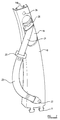
- Fig. 1 shows a carrier unit 10 which in this exemplified embodiment is itself made of plastic and is adapted to be fitted to the B- or C-column of a motor vehicle or part of the passenger seat.
- the B- or C-column and the seat parts are fixed to the vehicle and hence can act as anchorages.
- the carrier unit 10 has catches 11, 11a for fixing the carrier unit 10 on the anchorages during the final fitting of the carrier unit to B- or C-column, or to the seat.
- a belt retractor 12 is pre-fitted on the carrier unit 10 in the bottom zone thereof and is guided for displacement by lateral displacement projections 14 formed on the belt retractor 12 which are received in axially extending parallel displacement rails 13 formed on the inside of the carrier unit 10. From the belt retractor 10 the belt 15 extends to a height adjustment mechanism 16, on which a pillar loop 17, provided behind the cover, is arranged for vertical adjustment in manner known per se on a catch rail 18. Lateral displacement projections 14 and axially extending parallel displacement rails 13 are again provided, on the height adjustment mechanism 16 and carrier unit 10 respectively in the same way as in connection with the fixing of the belt retractor 12. Both the retractor 12 and the height adjustment mechanism may be moved axially of the carrier unit 10.
- the carrier unit 10 has a displaceable shutter 19 with a finger key 20 for actuating the height adjustment mechanism 16.
- the shoulder strap part 21 of the safety belt emerges through an aperture formed in the shutter 19.
- a tongue 22, adapted to be received in a seat belt buckle, is mounted on the strap dividing the shoulder strap part 21 from a lap belt part 23, the belt thus being a so-called three-point belt.
- the belt retractor 12 has at one side of the housing at its lower end an upwardly open U-shaped hook 24.
- the catch rail 18 facing the belt retractor and forming part of the height adjustment mechanism 16 two corresponding U-shaped hooks 25 are formed which are open towards the belt retractor 12.
- the carrier unit 10 constructed thus far is to be fitted on the anchorage, for example, the anchorage constituted by the B-column of the a motor vehicle
- the carrier unit 10 is placed in front of the said part, e.g. the B-column of the motor vehicle, and fixed in position by way of the catches 11, 11a.
- the belt retractor 12 locks, so that on further tension applied to the belt the retractor 12 and the catch rail 18 of the height adjustment mechanism 16 are moved towards one another.
- the U-shaped hooks 24, 25 engage corresponding openings provided for that purpose in the anchorage.
- the carrier unit 10 is secured to the anchorage by way of screws 26, 27 provided at its top and bottom ends, the screws 26, 27 extending through the catch rail 18 of the height adjustment mechanism 16 and the housing of the belt retractor 12 so as to fix these functional parts so that they will not rattle on the anchorage, and so that they will not move axially relative to the anchorage.
- the screw 27 extends through the belt retractor 12 and is aligned with the U-shaped hook 24 of the belt retractor.
- two hooks 24 are provided on the belt retractor 10 and the screw 27 may be symmetrically arranged with regard to the hooks.
- the screw 27 also fixes in position an end fitting of the lap part 23 of the strap, so that to this extent the screw 27 must be designed to take forces.
- other fixing points for the lap belt part 23 are possible, so that in that case a simple screw fastening of the carrier unit 10 on the anchorage is sufficient.
- the screws 26, 27 may alternatively be replaced by corresponding snap-in or catch connections as described in detail, for example, with reference to Figs. 4 and 4a.
- the carrier unit 10 is fitted to the B- or C-column by displacing the carrier unit 10 upwards as a whole after initial positioning until the U-shaped hooks 24 of the belt retractor 12 engage the associated openings in the anchorage.
- the height adjustment mechanism 16 is then adjusted manually from outside relatively to the carrier unit 10 until the hooks on the adjustment mechanism engage the associated openings on the anchorage, to fix the adjustment mechanism. In this way the functional parts 12, 16 can be brought into operative connection with the anchorage.
- Fig. 3 shows another embodiment of the invention in which, in addition to the height adjustment mechanism 16 and belt retractor 12 already described, a tightening mechanism 31 and a clamping device 33 coupled thereto are provided which are both pre-fitted on the carrier unit 10.
- the clamping mechanism 33 is so constructed in manner known per se as to respond to a sudden pulling out or tightening of the belt to clamp the belt securely to prevent any more belt from being pulled out.
- the clamping mechanism 33 is connected via a rod 32 to the tightening mechanism 31, and is guided for displacement via guide elements 34 shown laterally on the carrier unit 10. On actuation of the tightening mechanism 31 the clamping mechanism 33 is moved to tighten the strap clamped by the clamping mechanism 33.
- the clamping mechanism 33 transmits the forces it takes via an intermediate force limiting mechanism 50 to the tightening mechanism 31.
- the entire load is taken by the tightening mechanism 31 so that in the event of a crash the belt retractor 12 has no additional forces to take.
- only the height adjustment mechanism 16 and the tightening mechanism 31 are arranged to be displaceable with respect to the final fitting of the carrier unit 10 on the anchorage and are provided with corresponding connections to such anchorage.
- the carrier unit is of such stability that in normal operation of the belt retractor 12 it can take the forces the retractor has to take.
- a rod 28 extending through the carrier unit 10 is arranged for rotation on the latter and at one end has a locking crank 29 while its other end has a screw aperture 30.
- the carrier unit 10 is then fixed on the anchorage by rotating the rod 28 until the locking crank 29 engages in an associated configuration on the anchorage, whereafter the rod 28 is fixed to be non-rotatable by means of an appropriate screw in the screw aperture 30.
- a loop formed at the end of the lap strap 23 is slidably mounted on the rod 28.
- the loop may slide from an operative position to a non-operative position.
- An arrangement of this type may be of especial use in a two-door motor vehicle.
- Fig. 3 in conjunction with Figs. 4 and 4a shows a first alternative for the pre-fitting of the tightening mechanism 31 on the carrier unit 10 and the operative connection of the tightening mechanism 31 to the anchorage; the relative construction for the pre-fitting and fixing of the height adjustment mechanism 16 corresponds to the exemplified embodiment described with reference to Figs. 1 and 2.
- the tightening mechanism 31 is fixed in the central aperture 35a of a fixing plate 35, the latter being held or guided for displacement at a projection 37 on the inside of the carrier unit 10 by means of a corrugation or groove 36.
- the fixing plate 35 again has, like the construction in the case of the height adjustment mechanism 16, two upwardly extending projections 38, the fixing plate additionally being provided with corresponding catch and clip springs 39 (Fig. 4).
- Fig. 4a shows that the projections 38 engage in apertures 41 in a B-column 40, the catch and clip springs 39 simultaneously engaging in corresponding catch apertures 42 in the B-column.
- the fitting of the carrier unit 10 is thus completed in the same way as explained in connection with the preceding exemplified embodiment, i.e. the carrier unit 10 is first locked on the anchorage by way of the rod 28 and then tension is applied to the belt to release the clamping mechanism 33. A further tension on the belt results in the vertical adjustment mechanism 16 and the fixing plate 35 with the tightening mechanism 31 disposed thereon moving towards one another until the corresponding U-hooks 25 and projections 38 with catch springs 39 engage in the associated apertures on the anchorage and thus establish the operative connection between the functional parts of the safety belt system and the anchorage.
- a U-shaped stirrup 43 is provided which may be used as an alternative to, or in addition to, the fixing arrangements described above for the functional parts mounted on the carrier unit.
- the functional parts are connected to the carrier unit by cooperating projections and rails, such as projections 13 and rails 14, or by guide elements, such as the guide elements 34 which guide the clamping device. It is thought that if a vehicle in which such an arrangement is mounted is subjected to a side impact in excess of a specific severity, the main plastic part of the carrier unit may be deformed or damaged and the said projections and rails may be disengaged, or the guide elements may be disengaged from the elements that they guide. Similarly items that are fixed permanently in position on the main plastic part may become separated from the main plastic part.
- the U-shaped stirrup 43 may be used, for example, as an alternative or additional fixing for the tightening mechanism 31, but could be used for others of the functional parts.
- the stirrup 43 may be formed of metal and is mounted on the main plastic part of the carrier in a convenient manner.
- the stirrup has two projecting limbs, which extend from the main plastic part of the carrier towards the anchorage.
- the end face of each limb is provided with a catch arrangement 44 adapted to engage and be retained by the anchorage.
- the main part of the carrier also has projecting limbs with terminal enlargements 45 to engage the anchorage so that the main part of the carrier is held in position. It is to be observed that the limbs 43 are effectively longer than the limbs with the terminal enlargements 45 to ensure that as the carrier 10 is fixed in position initially the limbs 43 engage the anchorage, and subsequently the limbs carrying the terminal enlargements 45 engage the anchorage. This ensures that the stirrup 43 is correctly connected to the anchorage.
Landscapes
- Engineering & Computer Science (AREA)
- Mechanical Engineering (AREA)
- Manufacturing & Machinery (AREA)
- Chemical & Material Sciences (AREA)
- Combustion & Propulsion (AREA)
- Transportation (AREA)
- Automotive Seat Belt Assembly (AREA)
Description
Claims (20)
- A carrier unit (10) carrying the functional parts of a safety belt system, the combination of the carrier and the functional parts being adapted to be mounted on a vehicle anchorage, said functional parts comprising the belt retractor (12) and/or the pillar loop (17) and/or a height adjustment mechanism (16) for a pillar loop (17) and/or a clamping mechanism (33) for the belt (15) and/or a tightening mechanism (31), characterized in that at least one of the functional parts (12, 16, 17, 31, 33) is disposed on the carrier unit (10) for displacement relatively thereto to become operatively connected to the anchorage by means of said displacement which can be effected when the carrier unit (10) is fitted on the anchorage.
- A carrier unit (10) according to claim 1, having a pillar loop or height adjustment mechanism (16) disposed thereon, and with a belt retractor (12) disposed thereon, wherein the belt retractor (12) is pre-fitted on the carrier unit (10) at the bottom end thereof, and the pillar loop or height adjustment mechanism (16) is pre-fitted at the top end of the carrier unit (10) each have at least one upwardly open U-shaped hooks for engagement in the anchorage, and wherein the belt retractor (12) is disposed on the carrier unit (10) so as to be stationary and the height adjustment mechanism (16) is disposed on the carrier unit (10) so as to be displaceable.
- A carrier unit (10) according to claim 1 with a pillar loop or a height adjustment mechanism (16) disposed thereon and with a belt retractor (12) disposed thereon, wherein the belt retractor (12) pre-fitted on the carrier unit (10) at the bottom end thereof has, at least one U-shaped hook (24) open towards the height adjustment mechanism for engagement in the anchorage and the height adjustment mechanism (16) pre-fitted at the top end of the carrier unit (10) has least one U-shaped hook (25) open towards the belt retractor (12) for engagement in the anchorage.
- A carrier unit according to claim 2 or 3, wherein the pillar loop or height adjustment mechanism (16) and/or belt retractor (12) can be fixed in their end position on the carrier unit (10) by catch means after completion of the displacement movement produced during the fitting operation.
- A carrier unit according to any one of claims 2 to 4, characterised in that the carrier unit (10) is fixable on the anchorage after completion of the displacement by means of screws (26, 27) extending through the pillar loop or height adjustment mechanism (16) and the belt retractor (12) in their end position.
- A carrier according to any one of Claims 1 to 4 wherein the combination of the carrier and the functional parts is provided with snap-in/catch connections to retain the carrier on the anchorage.
- A carrier unit according to claim 5, wherein the screw (27) that serves to fix the carrier unit (10) and that extends through the belt retractor (12) also retains the lap part (23) of the belt.
- A carrier unit according to claim 1 with a pillar loop or a height adjustment mechanism (16), a belt retractor (12) and a tightening mechanism (31) disposed thereon and with a clamping mechanism (33) connected to the tightening mechanism (31), wherein the height adjustment mechanism (16) and the tightening mechanism (31) are disposed on the carrier unit (10) so as to be displaceable relatively thereto and become operatively connected to the anchorage by the displacement which can be produced on fitting of the carrier unit (10) on the anchorage.
- A carrier unit according to claim 8, wherein the pillar loop or the height adjustment mechanism (16) pre-fitted at the top end of the carrier unit (10) has at least one U-shaped hook (25) open towards the tightening mechanism (31) for engagement in the anchorage and the tightening mechanism (31) is fastened to a fixing element (35, 43) disposed for displacement on the carrier unit (10), the fixing element (35, 43) being adapted to engage operatively with the anchorage after completion of the displacement.
- A carrier unit according to claim 9, characterised in that the belt retractor (12) is fixed on the carrier unit (10) so as to be stationary.
- A carrier unit according to claim 9, characterised in that the fixing element for the tightening mechanism (31) is constructed as a fixing plate (35) having a central aperture (35a) receiving the tightening mechanism, and with a hook (38) open towards the height adjustment mechanism (16) for engagement in the anchorage, the fixing plate (35) having spring projections (39) for engagement in catch apertures (42) of the anchorage.
- A carrier unit according to claim 9, wherein the fixing element is constructed as a U-shaped stirrup (43) engaging around the tightening mechanism (31) and having, at the end faces of the limbs of the U, catch projections (44) for engagement in the anchorage.
- A carrier unit according to any one of claims 1 to 11 provided with at least one U-shaped stirrup (43) engaging around at least one of the functional parts and having at the end faces of the limbs of the U, catch projections (44) for engagement in the anchorage.
- A carrier unit according to any one of claims 8 to 12, wherein the tightening mechanism (31) is connected to a force limiter unit (50) disposed on the carrier unit (10).
- A carrier unit according to any one of claims 8 to 14, wherein a rotatable rod (28) with a locking crank (29) for engagement in the anchorage and a screw aperture (30) for non-rotatable fixing of the rod is provided at that end of the carrier unit (10) which is adjacent the belt retractor.
- A carrier unit according to claim 15, wherein the rod (28) serves to hold the lap part (23) of the belt.
- A carrier unit according to any one of claims 1 to 15, wherein the carrier unit (10) is constructed as a U-shaped plastic cover which accommodates the functional parts (12, 16, 31, 33) on its inside and which is adapted to be connected to the anchorage.
- A carrier unit according to claim 17 as dependent upon Claim 10 wherein the cover, of the carrier unit (10), has a stability such that it withstands the load required to be taken by the belt retractor (12) in normal operation thereof.
- A carrier unit according to any one of claims 1 to 18, wherein the carrier unit is adapted to be mounted on a B-column or C-column as the vehicle anchorage.
- A carrier unit according to any one of claims 1 to 18, wherein the carrier unit (10) is adapted to be fitted on a seat as the vehicle anchorage.
Applications Claiming Priority (3)
| Application Number | Priority Date | Filing Date | Title |
|---|---|---|---|
| DE4341119A DE4341119A1 (en) | 1993-12-02 | 1993-12-02 | Pre-assembled carrier unit for the functional parts of a seat belt system |
| DE4341119 | 1993-12-02 | ||
| PCT/SE1994/001164 WO1995015270A1 (en) | 1993-12-02 | 1994-12-02 | Pre-fitted carrier unit for the functional parts of a safety belt system |
Publications (2)
| Publication Number | Publication Date |
|---|---|
| EP0730536A1 EP0730536A1 (en) | 1996-09-11 |
| EP0730536B1 true EP0730536B1 (en) | 1998-09-30 |
Family
ID=6504031
Family Applications (1)
| Application Number | Title | Priority Date | Filing Date |
|---|---|---|---|
| EP95903095A Expired - Lifetime EP0730536B1 (en) | 1993-12-02 | 1994-12-02 | Pre-fitted carrier unit for the functional parts of a safety belt system |
Country Status (4)
| Country | Link |
|---|---|
| US (1) | US5769456A (en) |
| EP (1) | EP0730536B1 (en) |
| DE (2) | DE4341119A1 (en) |
| WO (1) | WO1995015270A1 (en) |
Cited By (5)
| Publication number | Priority date | Publication date | Assignee | Title |
|---|---|---|---|---|
| DE102018215364A1 (en) * | 2018-09-11 | 2020-03-12 | Volkswagen Aktiengesellschaft | Body structure for a vehicle |
| DE102018215366A1 (en) * | 2018-09-11 | 2020-03-12 | Volkswagen Aktiengesellschaft | Vehicle body |
| DE102018215365A1 (en) * | 2018-09-11 | 2020-03-12 | Volkswagen Aktiengesellschaft | Method of installing a seat belt assembly in a vehicle body |
| DE102018215367A1 (en) * | 2018-09-11 | 2020-03-12 | Volkswagen Aktiengesellschaft | Body structure for a vehicle |
| DE102019219129A1 (en) * | 2019-12-09 | 2021-06-10 | Volkswagen Aktiengesellschaft | Method of manufacturing a vehicle |
Families Citing this family (20)
| Publication number | Priority date | Publication date | Assignee | Title |
|---|---|---|---|---|
| DE19509887C2 (en) * | 1995-03-17 | 2000-06-21 | Hs Tech & Design | Belt retractor for a vehicle seat belt |
| DE19610861C2 (en) * | 1996-03-20 | 2001-06-21 | Autoliv Dev | Motor vehicle with shock absorber attachment of the deflection fitting |
| JPH10217905A (en) * | 1997-01-31 | 1998-08-18 | Suzuki Motor Corp | Mounting structure of seat belt adjuster |
| DE19818261B4 (en) * | 1998-04-23 | 2006-05-24 | Volkswagen Ag | Arrangement for guiding a belt within the vehicle frame of a motor vehicle |
| DE10011906C1 (en) | 2000-03-11 | 2001-08-09 | Porsche Ag | Device for a belt height adjuster of a seat belt system |
| DE10011908C1 (en) * | 2000-03-11 | 2001-03-15 | Porsche Ag | Belt height adjustment device for automobile seatbelt has deformation element at rear of ratchet rail and releasable fixing plate for absorption of head impact energy |
| DE20005145U1 (en) * | 2000-03-21 | 2000-08-10 | ACTS GmbH & Co. KG, 63877 Sailauf | Seat belt system pre-assembled on the B-pillar |
| JP2007022126A (en) * | 2005-07-12 | 2007-02-01 | Beat Sonic:Kk | Pillar cover |
| US7367590B2 (en) * | 2005-08-04 | 2008-05-06 | Key Safety Systems, Inc. | Seat belt assembly and method of installation |
| JP4771211B2 (en) | 2005-08-05 | 2011-09-14 | スズキ株式会社 | Seat belt device mounting structure with pretensioner mechanism |
| DE102006013649A1 (en) * | 2006-03-24 | 2007-09-27 | GM Global Technology Operations, Inc., Detroit | Method for securing seat belt fastening especially for rear seat in vehicle has a chassis mounting bracket with seat belt fastening on the outside |
| DE102008026230B4 (en) * | 2008-05-29 | 2012-02-02 | Takata-Petri Ag | Protective element for protecting a safety belt and arrangement with a protective element |
| DE102010018983B4 (en) * | 2010-05-03 | 2021-11-11 | Bayerische Motoren Werke Aktiengesellschaft | Attachment for a component, in particular on the body of a motor vehicle |
| FR2963593B1 (en) * | 2010-08-03 | 2012-07-27 | Peugeot Citroen Automobiles Sa | TOOL FOR ASSEMBLING A THREE-POINT SAFETY SEAT BELT RETURN DEVICE ON A VEHICLE ELEMENT, AND METHOD OF FIXING THE SAME |
| US9365184B2 (en) | 2012-07-13 | 2016-06-14 | Honda Motor Co., Ltd. | Vehicle structure comprising seatbelt device |
| US9428144B2 (en) * | 2014-08-19 | 2016-08-30 | Ford Global Technologies, Llc | Three piece hidden D-ring seat belt restraint |
| US9873405B2 (en) * | 2014-09-10 | 2018-01-23 | Zodiac Seats Us Llc | Seat belt twist link |
| US9499121B2 (en) | 2014-11-17 | 2016-11-22 | Indiana Mills & Manufacutring, Inc. | Web position adjustment and attenuation apparatus |
| KR20230090729A (en) * | 2021-12-15 | 2023-06-22 | 현대자동차주식회사 | Seat belt mounting structure |
| ES3035715A1 (en) * | 2024-03-05 | 2025-09-08 | Seat Sa | Interior trim of a vehicle pillar, pillar assembly comprising it and assembly method (Machine-translation by Google Translate, not legally binding) |
Family Cites Families (13)
| Publication number | Priority date | Publication date | Assignee | Title |
|---|---|---|---|---|
| DE2822210A1 (en) * | 1978-05-22 | 1979-11-29 | Autoflug Gmbh | DEVICE FOR FASTENING A BELT ROLLER FOR A SAFETY BELT |
| DE2932505C3 (en) * | 1979-08-10 | 1982-02-11 | Daimler-Benz Ag, 7000 Stuttgart | Device arranged on a hollow vehicle carrier for the stepwise height adjustment of the deflection fitting of a seat belt system |
| JPS5957048A (en) * | 1982-09-24 | 1984-04-02 | Honda Motor Co Ltd | Seat belt guide adjustment device |
| DE3426207A1 (en) * | 1984-07-17 | 1986-03-20 | Dr.Ing.H.C. F. Porsche Ag, 7000 Stuttgart | Device for vertically adjusting an upper holding point of a safety belt system |
| DE3530495A1 (en) * | 1985-08-27 | 1987-03-05 | Porsche Ag | SAFETY BELT, ESPECIALLY 3-POINT SAFETY BELT FOR VEHICLES, AIRPLANES OR THE LIKE |
| JPH0780440B2 (en) * | 1986-12-27 | 1995-08-30 | スズキ株式会社 | Seat belt device |
| DE3714644A1 (en) * | 1987-05-02 | 1988-12-01 | Daimler Benz Ag | Belt retractor of a safety-belt system arranged in a vehicle cavity |
| DE3715845A1 (en) * | 1987-05-12 | 1989-01-26 | Bsrd Ltd | Tensioning device for a safety belt of vehicles, especially motor vehicles |
| FR2619773B1 (en) * | 1987-08-31 | 1991-02-15 | Peugeot | ARRANGEMENT FOR MOUNTING AND FIXING A SEAT BELT ASSEMBLY |
| JP2590528B2 (en) * | 1988-05-09 | 1997-03-12 | スズキ株式会社 | Rear seat belt mounting structure |
| DE3924670A1 (en) * | 1988-08-16 | 1990-02-22 | Volkswagen Ag | Three-point seat belt assembly - has belt loop and sliding bar anchoring point close to floor |
| US5207453A (en) * | 1992-04-02 | 1993-05-04 | Chrysler Corp | Add-on structure for vehicle shoulder belt |
| DE4327717A1 (en) * | 1993-08-18 | 1995-02-23 | Opel Adam Ag | Attachment for a seat belt and its related components |
-
1993
- 1993-12-02 DE DE4341119A patent/DE4341119A1/en not_active Withdrawn
-
1994
- 1994-12-02 WO PCT/SE1994/001164 patent/WO1995015270A1/en not_active Ceased
- 1994-12-02 US US08/656,248 patent/US5769456A/en not_active Expired - Fee Related
- 1994-12-02 EP EP95903095A patent/EP0730536B1/en not_active Expired - Lifetime
- 1994-12-02 DE DE69413706T patent/DE69413706T2/en not_active Expired - Fee Related
Cited By (8)
| Publication number | Priority date | Publication date | Assignee | Title |
|---|---|---|---|---|
| DE102018215364A1 (en) * | 2018-09-11 | 2020-03-12 | Volkswagen Aktiengesellschaft | Body structure for a vehicle |
| DE102018215366A1 (en) * | 2018-09-11 | 2020-03-12 | Volkswagen Aktiengesellschaft | Vehicle body |
| DE102018215365A1 (en) * | 2018-09-11 | 2020-03-12 | Volkswagen Aktiengesellschaft | Method of installing a seat belt assembly in a vehicle body |
| DE102018215367A1 (en) * | 2018-09-11 | 2020-03-12 | Volkswagen Aktiengesellschaft | Body structure for a vehicle |
| DE102018215364B4 (en) | 2018-09-11 | 2022-12-22 | Volkswagen Aktiengesellschaft | Body structure for a vehicle |
| DE102018215365B4 (en) * | 2018-09-11 | 2025-12-24 | Volkswagen Aktiengesellschaft | Method for installing a seat belt assembly in a vehicle body |
| DE102018215366B4 (en) * | 2018-09-11 | 2025-12-31 | Volkswagen Aktiengesellschaft | vehicle body |
| DE102019219129A1 (en) * | 2019-12-09 | 2021-06-10 | Volkswagen Aktiengesellschaft | Method of manufacturing a vehicle |
Also Published As
| Publication number | Publication date |
|---|---|
| WO1995015270A1 (en) | 1995-06-08 |
| EP0730536A1 (en) | 1996-09-11 |
| DE4341119A1 (en) | 1995-06-08 |
| US5769456A (en) | 1998-06-23 |
| DE69413706T2 (en) | 1999-06-10 |
| DE69413706D1 (en) | 1998-11-05 |
Similar Documents
| Publication | Publication Date | Title |
|---|---|---|
| US5769456A (en) | Pre-fitted carrier unit for the functional parts of a safety belt system | |
| US5292181A (en) | Anti-cinch and anti-chafe seat belt system | |
| US7461866B2 (en) | Height adjuster with return spring | |
| US7278684B2 (en) | Retractable coupling apparatus | |
| US5411292A (en) | Seat belt system with locking guide loop assembly | |
| EP0380442B1 (en) | Anti-cinch seat belt system | |
| US6729693B2 (en) | Seat belt apparatus | |
| US8052170B2 (en) | Locking height adjuster for a seat belt | |
| US4923214A (en) | Seat belt anchorage | |
| US5188425A (en) | Pretensioning latching mechanism | |
| US4470618A (en) | Adjustable seat belt anchorage | |
| US4840404A (en) | Seat belt system having shoulder height support | |
| US4302031A (en) | Webbing anchor lock mechanism | |
| US5000481A (en) | Locking device for vehicle seat belts | |
| US8474873B2 (en) | Seat belt system in motor vehicles | |
| GB2097652A (en) | Vehicle seat belt anchor assembly | |
| EP0694436B1 (en) | Device for quick coupling of a child seat to a motor-vehicle seat | |
| US5794977A (en) | D-ring height adjuster | |
| EP0147059B1 (en) | Clamping means for a strap | |
| US4949994A (en) | Height adjustable shoulder belt guide loop | |
| US6186548B1 (en) | D-ring height adjuster | |
| US4989901A (en) | Vertical adjustment means for a fitting of a safety-belt restraining system in motor vehicles | |
| US5069483A (en) | Seat belt mount mechanism | |
| CA2477971C (en) | Apparatus for use on a safety belt system for restraining the movement of an occupant or child seat | |
| EP1173344B1 (en) | Method and device for a child's car safety-seat |
Legal Events
| Date | Code | Title | Description |
|---|---|---|---|
| PUAI | Public reference made under article 153(3) epc to a published international application that has entered the european phase |
Free format text: ORIGINAL CODE: 0009012 |
|
| 17P | Request for examination filed |
Effective date: 19960620 |
|
| AK | Designated contracting states |
Kind code of ref document: A1 Designated state(s): DE ES FR GB |
|
| GRAG | Despatch of communication of intention to grant |
Free format text: ORIGINAL CODE: EPIDOS AGRA |
|
| 17Q | First examination report despatched |
Effective date: 19980217 |
|
| GRAG | Despatch of communication of intention to grant |
Free format text: ORIGINAL CODE: EPIDOS AGRA |
|
| GRAH | Despatch of communication of intention to grant a patent |
Free format text: ORIGINAL CODE: EPIDOS IGRA |
|
| GRAH | Despatch of communication of intention to grant a patent |
Free format text: ORIGINAL CODE: EPIDOS IGRA |
|
| GRAA | (expected) grant |
Free format text: ORIGINAL CODE: 0009210 |
|
| AK | Designated contracting states |
Kind code of ref document: B1 Designated state(s): DE ES FR GB |
|
| PG25 | Lapsed in a contracting state [announced via postgrant information from national office to epo] |
Ref country code: FR Free format text: LAPSE BECAUSE OF FAILURE TO SUBMIT A TRANSLATION OF THE DESCRIPTION OR TO PAY THE FEE WITHIN THE PRESCRIBED TIME-LIMIT Effective date: 19980930 Ref country code: ES Free format text: THE PATENT HAS BEEN ANNULLED BY A DECISION OF A NATIONAL AUTHORITY Effective date: 19980930 |
|
| REF | Corresponds to: |
Ref document number: 69413706 Country of ref document: DE Date of ref document: 19981105 |
|
| EN | Fr: translation not filed | ||
| PLBE | No opposition filed within time limit |
Free format text: ORIGINAL CODE: 0009261 |
|
| STAA | Information on the status of an ep patent application or granted ep patent |
Free format text: STATUS: NO OPPOSITION FILED WITHIN TIME LIMIT |
|
| 26N | No opposition filed | ||
| REG | Reference to a national code |
Ref country code: GB Ref legal event code: IF02 |
|
| PGFP | Annual fee paid to national office [announced via postgrant information from national office to epo] |
Ref country code: DE Payment date: 20081022 Year of fee payment: 15 |
|
| PGFP | Annual fee paid to national office [announced via postgrant information from national office to epo] |
Ref country code: GB Payment date: 20081016 Year of fee payment: 15 |
|
| GBPC | Gb: european patent ceased through non-payment of renewal fee |
Effective date: 20091202 |
|
| PG25 | Lapsed in a contracting state [announced via postgrant information from national office to epo] |
Ref country code: DE Free format text: LAPSE BECAUSE OF NON-PAYMENT OF DUE FEES Effective date: 20100701 |
|
| PG25 | Lapsed in a contracting state [announced via postgrant information from national office to epo] |
Ref country code: GB Free format text: LAPSE BECAUSE OF NON-PAYMENT OF DUE FEES Effective date: 20091202 |