EP0730145A1 - ATR crystal and assembly for infrared microspectroscopy - Google Patents
ATR crystal and assembly for infrared microspectroscopy Download PDFInfo
- Publication number
- EP0730145A1 EP0730145A1 EP95301402A EP95301402A EP0730145A1 EP 0730145 A1 EP0730145 A1 EP 0730145A1 EP 95301402 A EP95301402 A EP 95301402A EP 95301402 A EP95301402 A EP 95301402A EP 0730145 A1 EP0730145 A1 EP 0730145A1
- Authority
- EP
- European Patent Office
- Prior art keywords
- crystal
- atr
- sample
- mounting assembly
- type crystal
- Prior art date
- Legal status (The legal status is an assumption and is not a legal conclusion. Google has not performed a legal analysis and makes no representation as to the accuracy of the status listed.)
- Granted
Links
- 239000013078 crystal Substances 0.000 title claims abstract description 56
- 238000004971 IR microspectroscopy Methods 0.000 title 1
- 230000005855 radiation Effects 0.000 claims description 19
- 238000004611 spectroscopical analysis Methods 0.000 claims description 9
- 239000000853 adhesive Substances 0.000 claims description 2
- 230000001070 adhesive effect Effects 0.000 claims description 2
- 238000004458 analytical method Methods 0.000 abstract description 6
- 238000011835 investigation Methods 0.000 abstract description 4
- 238000000386 microscopy Methods 0.000 abstract 1
- 238000005102 attenuated total reflection Methods 0.000 description 13
- 238000005259 measurement Methods 0.000 description 8
- 238000005033 Fourier transform infrared spectroscopy Methods 0.000 description 6
- 230000003287 optical effect Effects 0.000 description 3
- 230000008878 coupling Effects 0.000 description 2
- 238000010168 coupling process Methods 0.000 description 2
- 238000005859 coupling reaction Methods 0.000 description 2
- 210000003414 extremity Anatomy 0.000 description 2
- 229910052732 germanium Inorganic materials 0.000 description 2
- GNPVGFCGXDBREM-UHFFFAOYSA-N germanium atom Chemical compound [Ge] GNPVGFCGXDBREM-UHFFFAOYSA-N 0.000 description 2
- 239000000463 material Substances 0.000 description 2
- 238000000034 method Methods 0.000 description 2
- 230000002238 attenuated effect Effects 0.000 description 1
- 238000001210 attenuated total reflectance infrared spectroscopy Methods 0.000 description 1
- 238000002329 infrared spectrum Methods 0.000 description 1
- 210000003141 lower extremity Anatomy 0.000 description 1
- 230000002093 peripheral effect Effects 0.000 description 1
- 238000005070 sampling Methods 0.000 description 1
- SBIBMFFZSBJNJF-UHFFFAOYSA-N selenium;zinc Chemical compound [Se]=[Zn] SBIBMFFZSBJNJF-UHFFFAOYSA-N 0.000 description 1
- 229910052710 silicon Inorganic materials 0.000 description 1
- 239000010703 silicon Substances 0.000 description 1
- 238000002834 transmittance Methods 0.000 description 1
- 230000000007 visual effect Effects 0.000 description 1
Images


Classifications
-
- G—PHYSICS
- G02—OPTICS
- G02B—OPTICAL ELEMENTS, SYSTEMS OR APPARATUS
- G02B21/00—Microscopes
- G02B21/02—Objectives
- G02B21/04—Objectives involving mirrors
-
- G—PHYSICS
- G01—MEASURING; TESTING
- G01N—INVESTIGATING OR ANALYSING MATERIALS BY DETERMINING THEIR CHEMICAL OR PHYSICAL PROPERTIES
- G01N21/00—Investigating or analysing materials by the use of optical means, i.e. using sub-millimetre waves, infrared, visible or ultraviolet light
- G01N21/17—Systems in which incident light is modified in accordance with the properties of the material investigated
- G01N21/55—Specular reflectivity
- G01N21/552—Attenuated total reflection
Definitions
- This invention relates to apparatus for carrying out spectroscopic analysis of samples.
- Such apparatus typically includes a source of visible radiation and a source of radiant energy in the non-visible wavelength range, typically radiation in the infrared (IR) range.
- the infrared radiation is used to undertake spectroscopic analysis of the sample.
- a known apparatus of this type is an FT-IR microscope such as that manufactured by Perkin-Elmer.
- This type of microscope can be used to analyse very small samples.
- the sample can be mounted on a stage between an objective lens and a condenser lens.
- the microscope can be used in either a transmitting mode or a reflecting mode.
- the reflecting mode is usually employed when the sample under investigation is non-transmitting to the analysing radiation.
- the microscope is usually used in conjunction with an IR spectrophotometer to obtain an IR spectrum of the sample.
- ATR attenuated total reflection
- a crystal which utilises total internal reflection or attenuated total internal reflection is located in contact with the sample during the analysis step. Contact between the sample and the crystal is usually maintained by the application of pressure.
- the crystals have been of a hemispherical shape with the lower surface of the hemisphere being in contact with the sample. Examples of apparatus making use of such crystals are described in US-A-5093580, JP-A-4-348254 and JP-A-5-164972.
- the crystals are usually made of an infrared transmitting material such as ZnSe or germanium. In some prior art apparatus the crystals are mounted so that they can be moved out of contact with the sample in order to permit visual observation of the sample during a setting-up stage.
- the sample With the crystal in its removed position the sample is viewed e.g. through an optical microscope and the area of interest identified and positioned appropriately. The crystal is then brought into contact with the sample and then analysed with the microscope in its infrared mode.
- the present invention is concerned with an apparatus in which these problems are alleviated.
- One aspect of the present invention provides an ATR type crystal for use in apparatus for carrying out spectroscopic analysis which comprises a crystal body which has an upper body portion through which analysing radiation can pass towards a sample to be analysed, and a generally conical lower part whose apex in use is in contact with the sample.
- the upper body portion may be part spherical and the radiation may pass therethrough substantially without refraction.
- the crystal body may have a flat upper surface to allow bonding to a support.
- the contact surface of the apex will have dimensions usually in the range 50 microns to 200 microns, with a typical value being of the order of 100 microns.
- the second member may be located axially within an outer tubular first member so that said members can undergo relative axial movement.
- the ATR type crystal may be secured by adhesive to the lower end of the second member.
- the bias means may comprise a spring disposed within the upper portion of the first tubular member.
- the support means may include means permitting adjustment of the bias exerted by the spring on the second member.
- Such a mounting assembly may be provided as an attachment for an existing apparatus for carrying out spectroscopic analysis such as the FT-IR microscope.
- Figure 1 shows the principal elements of an FT-IR microscope such as that manufactured by Perkin-Elmer.
- the microscope includes an optical microscope (10) which is disposed above a view/IR mirror (11) which in turn is disposed above a remote aperture (12).
- a transmittance/reflectance mirror (14) which is positioned above an objective Cassegrain assembly (16) and a condenser Cassegrain assembly (18).
- a sample position (20) usually a stage.
- a flat mirror (22) which can direct radiation from a toroid coupling optic (24) which in turn is configured to receive radiation from a radiation source, typically a visible radiation source or an infrared radiation source.
- the apparatus also includes a detector and an MCT Cassegrain arrangement (26) which is used to carry out the spectroscopic analysis in conjunction with an IR spectrophotometer (not shown).
- the microscope includes a source of visible radiation and can also be coupled to a source of infrared radiation which usually is contained in an associated spectrophotometer. These sources are not shown on Figure 1.
- a first step in analysing a sample using a microscope of the type shown in Figure 1 is viewing the sample to identify the area to be investigated.
- the configuration of the microscope during sample viewing is shown in Figure 2.
- an input beam of radiation from the visible light source is directed towards the reflectance mirror (14) and reflected towards the objective Cassegrain (16). From the Cassegrain the light beam passes to the sample position and light is returned via the objective Cassegrain to the optical microscope (10).
- the configuration in this mode is illustrated in Figure 3.
- the input beam of analysing radiation again passes towards the reflectance mirror (14) and through the objective Cassegrain (16) towards the sample position (20). From the sample the beam is reflected upwardly via the objective Cassegrain through the remote aperture (12) to the mirror (11).
- the mirror (11) is a movable element which is not in its operative position during the viewing configuration of Figure 2, but is placed in that position for the analysis. From the mirror (11) the beam is directed towards the detecting arrangement, which enables spectroscopic analysis to be undertaken.
- Figure 2 the configuration of the microscope as shown in Figure 2 is its reflectance mode.
- Figures 4 and 5 are views equivalent to Figures 2 and 3 illustrating the position of the ATR crystal (40) during sample viewing ( Figure 4) and during an actual analysis measurement ( Figure 5).
- the crystal is in contact with the sample and the basic principles upon which the crystal operates will be appreciated by those skilled in the art.
- the present arrangement is concerned with the particular form of the ATR crystal employed.
- the crystal is shown in detail in Figures 6a to 6c.
- the crystal comprises a cylindrical intermediate portion (60), an upper portion (61) having a part spherical surface (62) and a flat top (63) and a lower generally conical portion (65).
- the crystal typically is formed from a material which transmits infrared radiation, e.g. germanium or silicon. Approximate dimensions of the crystal are as follows.
- the radius of the intermediate portion (60) is of the order of 2mm
- the total axial extent of the crystal is of the order of 3mm
- the apex (66) of the cone is formed with a small flat surface whose dimensions are typically 100 microns, but can be in the range of approximately 50 microns to 200 microns.
- FIGs 7a and 7b illustrate in more detail the position of the crystal (40) during the viewing and measurement modes.
- the spherical surface (62) is shaped such that incident radiation is substantially normal to the surface (62) and thus passes through without refraction.
- incident radiation is substantially normal to the surface (62) and thus passes through without refraction.
- the use of the relatively small area enables a relatively high pressure contact to be formed between the sample and crystal without any increase in the contact area between them. This assists in obtaining reliable measurements. Because of the reproducibility of position and area of the sample and the contact pressure, the design of crystal gives higher sampling reproducibility for ATR spectroscopy.
- the crystal (40) can be incorporated into a mounting assembly of the type shown in Figures 8 to 11 of the drawings.
- This assembly can be incorporated into existing spectroscopic apparatus such as the FT-IR microscope.
- the arrangement shown in Figures 8 to 11 is designed to fit into the Perkin-Elmer FT/IR microscope and, in particular, to be attached to the objective Cassegrain (16) of that microscope.
- the mounting assembly includes a frame structure having radially extending limbs (70) connected to a ring (71), the frame structure being coupled to the Cassegrain objective at angularly spaced peripheral positions by means of screw connectors (72).
- the frame structure supports a downwardly extending mounting assembly which comprises an outer tubular member (74) within which is located an axially movable member (76).
- the axially movable member has a tapering lower portion which carries at its lower extremity the crystal (40) shown in Figure 6.
- a spring (78) is located within the tubular member (74) and acts to bias the inner member downwardly.
- a nut (80) engages the outer threaded portion of the second member and can be used to adjust the axial position of the crystal.
- the crystal can be raised and lowered by means of a manually operable toggle bar (82) which can be manually operated to move the second member upwardly or downwardly.
- the inner and outer members (74 and 76) are coupled by a bayonet type coupling in which a radially outwardly projecting pin on the inner member (76) engages in a slot in the outer member (76).
- a bayonet type coupling in which a radially outwardly projecting pin on the inner member (76) engages in a slot in the outer member (76).
- the toggle bar is then twisted so that bayonet connection maintains that position in a manner similar to a light bulb connection.
- To lower the crystal the toggle bar (82) is twisted to release the bayonet connection and the member (76) can then fall to its lower position.
Landscapes
- Physics & Mathematics (AREA)
- Chemical & Material Sciences (AREA)
- Analytical Chemistry (AREA)
- General Physics & Mathematics (AREA)
- Health & Medical Sciences (AREA)
- Life Sciences & Earth Sciences (AREA)
- Biochemistry (AREA)
- General Health & Medical Sciences (AREA)
- Immunology (AREA)
- Pathology (AREA)
- Optics & Photonics (AREA)
- Investigating Or Analysing Materials By Optical Means (AREA)
Abstract
Description
- This invention relates to apparatus for carrying out spectroscopic analysis of samples. Such apparatus typically includes a source of visible radiation and a source of radiant energy in the non-visible wavelength range, typically radiation in the infrared (IR) range. The infrared radiation is used to undertake spectroscopic analysis of the sample.
- A known apparatus of this type is an FT-IR microscope such as that manufactured by Perkin-Elmer. This type of microscope can be used to analyse very small samples. The sample can be mounted on a stage between an objective lens and a condenser lens. In general terms the microscope can be used in either a transmitting mode or a reflecting mode. The reflecting mode is usually employed when the sample under investigation is non-transmitting to the analysing radiation. The microscope is usually used in conjunction with an IR spectrophotometer to obtain an IR spectrum of the sample.
- When poorly reflecting samples are analysed in the reflecting mode it is known to use what is called the attenuated total reflection (ATR) technique. In this, a crystal which utilises total internal reflection or attenuated total internal reflection, is located in contact with the sample during the analysis step. Contact between the sample and the crystal is usually maintained by the application of pressure. Conventionally the crystals have been of a hemispherical shape with the lower surface of the hemisphere being in contact with the sample. Examples of apparatus making use of such crystals are described in US-A-5093580, JP-A-4-348254 and JP-A-5-164972. The crystals are usually made of an infrared transmitting material such as ZnSe or germanium. In some prior art apparatus the crystals are mounted so that they can be moved out of contact with the sample in order to permit visual observation of the sample during a setting-up stage.
- With the crystal in its removed position the sample is viewed e.g. through an optical microscope and the area of interest identified and positioned appropriately. The crystal is then brought into contact with the sample and then analysed with the microscope in its infrared mode.
- There are two significant problems with the conventional arrangements which make use of hemispherical crystals. One is uncertainty concerning the actual area of the sample being analysed and the other is creating sufficient pressure between the crystal and the sample at the area of contact in order to obtain a reliable measurement.
- The present invention is concerned with an apparatus in which these problems are alleviated.
- One aspect of the present invention provides an ATR type crystal for use in apparatus for carrying out spectroscopic analysis which comprises a crystal body which has an upper body portion through which analysing radiation can pass towards a sample to be analysed, and a generally conical lower part whose apex in use is in contact with the sample.
- The upper body portion may be part spherical and the radiation may pass therethrough substantially without refraction.
- By means of such an arrangement it is possible to create a relatively small, flat surface at the apex of the cone to provide a known area of contact with the sample. Furthermore, because the area provided by the apex of the cone is relatively small the crystal can be used to develop a high pressure contact between the sample and crystal without increasing the area of contact.
- The crystal body may have a flat upper surface to allow bonding to a support. The contact surface of the apex will have dimensions usually in the range 50 microns to 200 microns, with a typical value being of the order of 100 microns.
- Another aspect of the present invention provides a mounting assembly for an ATR type crystal which comprises a frame having generally radially extending limbs attachable to an objective lens of an apparatus for carrying out spectroscopic analysis, an axially depending support element carried by said frame, said support element including first and second relatively movable members, the second of which carries on its lower end an ATR type crystal of the type defined in said one aspect, and means biasing said second member to its lowermost position and means allowing movement of the second member upwardly against said bias means.
- The second member may be located axially within an outer tubular first member so that said members can undergo relative axial movement. The ATR type crystal may be secured by adhesive to the lower end of the second member. The bias means may comprise a spring disposed within the upper portion of the first tubular member. The support means may include means permitting adjustment of the bias exerted by the spring on the second member.
- Such a mounting assembly may be provided as an attachment for an existing apparatus for carrying out spectroscopic analysis such as the FT-IR microscope.
- The invention will be described now by way of example only, with particular reference to the accompanying drawings. In the drawings:
- Figure 1 is a schematic side view illustrating the principal elements of an FT-IR microscope;
- Figures 2 and 3 are views similar to Figure 1 illustrating the operation of the microscope;
- Figures 4 and 5 are schematic views showing the ATR technique;
- Figures 6a to 6c are, respectively, plan, side and bottom views of an ATR crystal in accordance with the present invention;
- Figure 7a is a side schematic view showing the ATR crystal in its position during viewing of the sample;
- Figure 7b is a view similar to Figure 7a showing the crystal in its position during a measurement step,
- Figure 8 is a side view of a mounting assembly for an ATR crystal;
- Figure 9 is a perspective view from below of the mounting assembly;
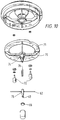
- Figure 10 is an exploded view of the mounting assembly, and
- Figure 11 is a side elevation of the mounting assembly with the crystal in its raised position.
- Figure 1 shows the principal elements of an FT-IR microscope such as that manufactured by Perkin-Elmer. The microscope includes an optical microscope (10) which is disposed above a view/IR mirror (11) which in turn is disposed above a remote aperture (12). Below the remote aperture (12) is located a transmittance/reflectance mirror (14) which is positioned above an objective Cassegrain assembly (16) and a condenser Cassegrain assembly (18). Between the two Cassegrains is disposed a sample position (20) usually a stage. Below the condenser Cassegrain (18) there is a flat mirror (22) which can direct radiation from a toroid coupling optic (24) which in turn is configured to receive radiation from a radiation source, typically a visible radiation source or an infrared radiation source. The apparatus also includes a detector and an MCT Cassegrain arrangement (26) which is used to carry out the spectroscopic analysis in conjunction with an IR spectrophotometer (not shown).
- It will be appreciated that the microscope includes a source of visible radiation and can also be coupled to a source of infrared radiation which usually is contained in an associated spectrophotometer. These sources are not shown on Figure 1.
- Those skilled in the art will appreciate the manner in which such a microscope operates and a full explanation of this operation is not required for purpose of understanding the present invention. A fuller description of the microscope can be found in an article entitled an FTIR microscope by D.W. Shearing, E.F. Young, and T.P. Byron published in American Laboratory, November 1990 and also in the user's manual of The Perkin-Elmer FT/IR microscope.
- Briefly, it will be appreciated that a first step in analysing a sample using a microscope of the type shown in Figure 1 is viewing the sample to identify the area to be investigated. The configuration of the microscope during sample viewing is shown in Figure 2. In this arrangement an input beam of radiation from the visible light source is directed towards the reflectance mirror (14) and reflected towards the objective Cassegrain (16). From the Cassegrain the light beam passes to the sample position and light is returned via the objective Cassegrain to the optical microscope (10).
- Once the sample has been positioned correctly on its stage, a standard reflectance measurement can then be undertaken and the configuration in this mode is illustrated in Figure 3. The input beam of analysing radiation again passes towards the reflectance mirror (14) and through the objective Cassegrain (16) towards the sample position (20). From the sample the beam is reflected upwardly via the objective Cassegrain through the remote aperture (12) to the mirror (11). It needs to be noted that the mirror (11) is a movable element which is not in its operative position during the viewing configuration of Figure 2, but is placed in that position for the analysis. From the mirror (11) the beam is directed towards the detecting arrangement, which enables spectroscopic analysis to be undertaken.
- It will be further appreciated that the configuration of the microscope as shown in Figure 2 is its reflectance mode. When a poorly reflecting sample is under investigation it is known to make use of an ATR crystal which is supported intermediate the objective Cassegrain and the sample. Figures 4 and 5 are views equivalent to Figures 2 and 3 illustrating the position of the ATR crystal (40) during sample viewing (Figure 4) and during an actual analysis measurement (Figure 5). During the analysis measurement the crystal is in contact with the sample and the basic principles upon which the crystal operates will be appreciated by those skilled in the art.
- The present arrangement is concerned with the particular form of the ATR crystal employed. The crystal is shown in detail in Figures 6a to 6c. The crystal comprises a cylindrical intermediate portion (60), an upper portion (61) having a part spherical surface (62) and a flat top (63) and a lower generally conical portion (65). The crystal typically is formed from a material which transmits infrared radiation, e.g. germanium or silicon. Approximate dimensions of the crystal are as follows. The radius of the intermediate portion (60) is of the order of 2mm, the total axial extent of the crystal is of the order of 3mm and the apex (66) of the cone is formed with a small flat surface whose dimensions are typically 100 microns, but can be in the range of approximately 50 microns to 200 microns.
- In the present arrangement it is proposed to support the crystal from the Cassegrain objective in the manner illustrated in Figures 4 and 5. Figures 7a and 7b illustrate in more detail the position of the crystal (40) during the viewing and measurement modes. As can be seen in the viewing mode the visible radiation does not pass through the crystal whilst in the measurement mode it does. The spherical surface (62) is shaped such that incident radiation is substantially normal to the surface (62) and thus passes through without refraction. Of significance is the fact that only the flat face of the apex of the conical portion is in contact with the sample under investigation. The significance of this is that it provides a known area of contact in a specific and reproducible manner for a large variety of samples. Furthermore, the use of the relatively small area enables a relatively high pressure contact to be formed between the sample and crystal without any increase in the contact area between them. This assists in obtaining reliable measurements. Because of the reproducibility of position and area of the sample and the contact pressure, the design of crystal gives higher sampling reproducibility for ATR spectroscopy.
- The crystal (40) can be incorporated into a mounting assembly of the type shown in Figures 8 to 11 of the drawings. This assembly can be incorporated into existing spectroscopic apparatus such as the FT-IR microscope. The arrangement shown in Figures 8 to 11 is designed to fit into the Perkin-Elmer FT/IR microscope and, in particular, to be attached to the objective Cassegrain (16) of that microscope. The mounting assembly includes a frame structure having radially extending limbs (70) connected to a ring (71), the frame structure being coupled to the Cassegrain objective at angularly spaced peripheral positions by means of screw connectors (72). At a central position the frame structure supports a downwardly extending mounting assembly which comprises an outer tubular member (74) within which is located an axially movable member (76). The axially movable member has a tapering lower portion which carries at its lower extremity the crystal (40) shown in Figure 6. A spring (78) is located within the tubular member (74) and acts to bias the inner member downwardly. A nut (80) engages the outer threaded portion of the second member and can be used to adjust the axial position of the crystal. The crystal can be raised and lowered by means of a manually operable toggle bar (82) which can be manually operated to move the second member upwardly or downwardly.
- The inner and outer members (74 and 76) are coupled by a bayonet type coupling in which a radially outwardly projecting pin on the inner member (76) engages in a slot in the outer member (76). To move the crystal to an upper position the toggle is pushed upwardly to move the member (76) upwardly against the spring bias. The toggle bar is then twisted so that bayonet connection maintains that position in a manner similar to a light bulb connection. To lower the crystal the toggle bar (82) is twisted to release the bayonet connection and the member (76) can then fall to its lower position.
Claims (9)
- An ATR type crystal for use in apparatus for carrying out spectroscopic analysis which comprises a crystal body which has an upper body portion through which analysing radiation can pass towards a sample to be analysed, and a generally conical lower part whose apex in use is in contact with the sample.
- An ATR type crystal according to claim 1, wherein the upper body position is part spherical and the readiation can pass therethrough substantially without refraction.
- An ATR crystal according to claim 1 or claim 2, wherein the crystal body has a flat upper surface to allow bonding to a support.
- An ATR crystal according to any preceding claim, wherein the contact surface at the apex of the conical part has dimensions usually in the range 50 microns to 200 microns, with a typical value being of the order of 100 microns.
- A mounting assembly for an ATR type crystal which comprises a frame having generally radially extending limbs attachable to an objective lens of an apparatus for carrying out spectroscopic analysis, an axially depending support element carried by said frame, said support element including first and second relatively movable members, the second of which carries on its lower end an ATR type crystal of the type defined in any one of claims 1 to 3, and means biasing said second member to its lowermost position and means allowing movement of the second member upwardly against said bias means.
- A mounting assembly according to claim 6, wherein the second member may be located axially within an outer tubular first member so that said members can undergo relative axial movement.
- A mounting assembly according to claims 5 or 6, wherein the ATR type crystal is secured by adhesive to the lower end of the second member.
- A mounting assembly according to any one of claims 5 to 7, wherein the bias means comprises a spring disposed within the upper portion of the first tubular member.
- A mounting assembly according to claim 8, wherein the support means includes means permitting adjustment of the bias exerted by the spring on the second member.
Priority Applications (4)
| Application Number | Priority Date | Filing Date | Title |
|---|---|---|---|
| DE69530473T DE69530473T2 (en) | 1995-03-03 | 1995-03-03 | ATR crystal support (attenuated total reflection) for infrared microspectroscopy |
| EP95301402A EP0730145B1 (en) | 1995-03-03 | 1995-03-03 | ATR crystal mounting assembly for infrared microspectroscopy |
| US08/608,653 US5729018A (en) | 1995-03-03 | 1996-02-29 | Air crystal and assembly for infrared microspectroscopy |
| JP04647896A JP3830571B2 (en) | 1995-03-03 | 1996-03-04 | Mounting assembly for ATR type crystals |
Applications Claiming Priority (1)
| Application Number | Priority Date | Filing Date | Title |
|---|---|---|---|
| EP95301402A EP0730145B1 (en) | 1995-03-03 | 1995-03-03 | ATR crystal mounting assembly for infrared microspectroscopy |
Publications (2)
| Publication Number | Publication Date |
|---|---|
| EP0730145A1 true EP0730145A1 (en) | 1996-09-04 |
| EP0730145B1 EP0730145B1 (en) | 2003-04-23 |
Family
ID=8221107
Family Applications (1)
| Application Number | Title | Priority Date | Filing Date |
|---|---|---|---|
| EP95301402A Expired - Lifetime EP0730145B1 (en) | 1995-03-03 | 1995-03-03 | ATR crystal mounting assembly for infrared microspectroscopy |
Country Status (4)
| Country | Link |
|---|---|
| US (1) | US5729018A (en) |
| EP (1) | EP0730145B1 (en) |
| JP (1) | JP3830571B2 (en) |
| DE (1) | DE69530473T2 (en) |
Cited By (2)
| Publication number | Priority date | Publication date | Assignee | Title |
|---|---|---|---|---|
| WO2007122416A1 (en) * | 2006-04-26 | 2007-11-01 | Perkinelmer Singapore Pte Ltd | Accessory for attenuated total internal reflectance (atr) spectroscopy |
| US8873140B2 (en) | 2010-07-09 | 2014-10-28 | Bruker Optik Gmbh | ATR objective for an IR microscope and method for operation thereof |
Families Citing this family (7)
| Publication number | Priority date | Publication date | Assignee | Title |
|---|---|---|---|---|
| JP3770707B2 (en) * | 1997-08-26 | 2006-04-26 | 松下電器産業株式会社 | Attenuated total reflection measuring apparatus and method for measuring specific components using the same |
| DE19808226C1 (en) * | 1998-02-27 | 2000-03-02 | Bruker Analytik Gmbh | Investigating hydrophilic macromolecules in an aqueous solution by attaching them to a lipid film on a solid carrier |
| TW588156B (en) * | 2002-12-24 | 2004-05-21 | Ind Tech Res Inst | Real time infrared chemical imaging spectrometry |
| US20070170362A1 (en) * | 2006-01-25 | 2007-07-26 | The Regents Of The University Of California | Method and apparatus for internal reflection imaging |
| AU2012203826B2 (en) * | 2006-04-26 | 2013-08-01 | Perkinelmer Singapore Pte Ltd | Accessory for attenuated total internal reflectance (ATR) spectroscopy |
| US8093559B1 (en) * | 2008-12-02 | 2012-01-10 | Hrl Laboratories, Llc | Methods and apparatus for three-color infrared sensors |
| US9863877B2 (en) * | 2015-09-23 | 2018-01-09 | Agilent Technologies, Inc. | Infrared spectrometer and scanner utilizing attenuated total reflection |
Citations (2)
| Publication number | Priority date | Publication date | Assignee | Title |
|---|---|---|---|---|
| EP0516481A2 (en) * | 1991-05-31 | 1992-12-02 | Donald W. Sting | Internal reflectance element with very small sample contacting surface |
| EP0529999A2 (en) * | 1991-08-27 | 1993-03-03 | Donald W. Sting | Radiant energy spectroscopy system |
Family Cites Families (1)
| Publication number | Priority date | Publication date | Assignee | Title |
|---|---|---|---|---|
| US5093580A (en) * | 1990-03-02 | 1992-03-03 | Spectra-Tech, Inc. | ATR objective and method for sample analyzation using an ATR crystal |
-
1995
- 1995-03-03 EP EP95301402A patent/EP0730145B1/en not_active Expired - Lifetime
- 1995-03-03 DE DE69530473T patent/DE69530473T2/en not_active Expired - Lifetime
-
1996
- 1996-02-29 US US08/608,653 patent/US5729018A/en not_active Expired - Lifetime
- 1996-03-04 JP JP04647896A patent/JP3830571B2/en not_active Expired - Lifetime
Patent Citations (2)
| Publication number | Priority date | Publication date | Assignee | Title |
|---|---|---|---|---|
| EP0516481A2 (en) * | 1991-05-31 | 1992-12-02 | Donald W. Sting | Internal reflectance element with very small sample contacting surface |
| EP0529999A2 (en) * | 1991-08-27 | 1993-03-03 | Donald W. Sting | Radiant energy spectroscopy system |
Cited By (14)
| Publication number | Priority date | Publication date | Assignee | Title |
|---|---|---|---|---|
| WO2007122416A1 (en) * | 2006-04-26 | 2007-11-01 | Perkinelmer Singapore Pte Ltd | Accessory for attenuated total internal reflectance (atr) spectroscopy |
| WO2007122414A1 (en) * | 2006-04-26 | 2007-11-01 | Perkinelmer Singapore Pte Ltd | Accessory for attenuated total internal reflectance (atr) spectroscopy |
| WO2007122415A1 (en) * | 2006-04-26 | 2007-11-01 | Perkinelmer Singapore Pte Ltd | Accessory for attenuated total internal reflectance (atr) spectroscopy |
| WO2007125329A3 (en) * | 2006-04-26 | 2008-01-31 | Perkinelmer Singapore Pte Ltd | Accessory for attenuated total internal reflectance (atr) spectroscopy |
| EP2113766A1 (en) | 2006-04-26 | 2009-11-04 | PerkinElmer Singapore Pte. Ltd. | Accessory for attenuated total internal reflectance (ATR) spectroscopy |
| CN101479638B (en) * | 2006-04-26 | 2011-02-16 | 珀金埃尔默新加坡有限公司 | Accessories for Attenuated Total Reflection (ATR) Spectrometers |
| US7935929B2 (en) | 2006-04-26 | 2011-05-03 | Perkinelmer Singapore Pte Ltd. | Accessory for attenuated total internal reflectance (ATR) spectroscopy |
| EP2322968A1 (en) | 2006-04-26 | 2011-05-18 | Perkinelmer Singapore PTE Ltd. | Accessory for Attenuated Total Internal Reflectance (ATR) Spectroscopy |
| CN101479639B (en) * | 2006-04-26 | 2011-07-13 | 珀金埃尔默新加坡有限公司 | Accessories for Attenuated Total Reflection (ATR) Spectrometers |
| US8223429B2 (en) | 2006-04-26 | 2012-07-17 | Perkinelmer Singapore Pte Ltd. | Accessory for attenuated total internal reflective (ATR) spectroscopy |
| US8223430B2 (en) | 2006-04-26 | 2012-07-17 | Perkinelmer Singapore Pte Ltd. | Accessory for attenuated total internal reflectance (ATR) spectroscopy |
| US8400711B2 (en) | 2006-04-26 | 2013-03-19 | Perkinelmer Singapore Pte Ltd. | Accessory for attenuated total internal reflectance (ATR) spectroscopy |
| US8743456B2 (en) | 2006-04-26 | 2014-06-03 | Perkinelmer Singapore Pte Ltd. | Systems and methods for attenuated total internal reflectance (ATR) spectroscopy |
| US8873140B2 (en) | 2010-07-09 | 2014-10-28 | Bruker Optik Gmbh | ATR objective for an IR microscope and method for operation thereof |
Also Published As
| Publication number | Publication date |
|---|---|
| DE69530473D1 (en) | 2003-05-28 |
| EP0730145B1 (en) | 2003-04-23 |
| DE69530473T2 (en) | 2003-11-20 |
| JP3830571B2 (en) | 2006-10-04 |
| JPH08320289A (en) | 1996-12-03 |
| US5729018A (en) | 1998-03-17 |
Similar Documents
| Publication | Publication Date | Title |
|---|---|---|
| US5172182A (en) | Internal reflectance element with very small sample contacting surface | |
| US5581085A (en) | Infrared microspectrometer accessory | |
| EP0815434B1 (en) | Diffuse reflectance probe | |
| US6693280B2 (en) | Mid-infrared spectrometer attachment to light microscopes | |
| US7573570B2 (en) | Compact Raman or fluorescence excitation system | |
| EP2021855B1 (en) | Accessory for attenuated total internal reflectance (atr) spectroscopy | |
| EP0730145B1 (en) | ATR crystal mounting assembly for infrared microspectroscopy | |
| US4991958A (en) | Micropipette adaptor for spectrophotometers | |
| JPH08500183A (en) | Spectroscopic device for the analysis of small and trace substances | |
| JP2010537165A (en) | Wide spectrometer | |
| US7446317B2 (en) | Multipass cell for gas analysis using a coherent optical source | |
| US4835389A (en) | Internal reflection spectroscopy for deep container immersion | |
| US5347364A (en) | Total reflection measuring apparatus | |
| US4922104A (en) | Infrared microspectrometer | |
| US4311387A (en) | Flow-through sample cell and collecting and illuminating optics for liquid chromatography | |
| EP0860694B1 (en) | Infrared spectrometer | |
| US5214286A (en) | Horizontal multiple internal reflection accessory for internal reflection spectroscopy | |
| US5308983A (en) | Spectroscopic accessory with microscope illuminator | |
| JP2023069567A (en) | Total reflection measurement apparatus | |
| JPH04116452A (en) | Microscopic infrared atr measuring apparatus | |
| US20150146201A1 (en) | Optical probe with extended working distance | |
| JPH11166889A (en) | ATR crystal support structure | |
| JP2001174708A (en) | Infrared microscope | |
| RU2334957C2 (en) | Device for spectra measurement of akh kuptsov | |
| JPH0610653B2 (en) | Infrared microscope |
Legal Events
| Date | Code | Title | Description |
|---|---|---|---|
| PUAI | Public reference made under article 153(3) epc to a published international application that has entered the european phase |
Free format text: ORIGINAL CODE: 0009012 |
|
| AK | Designated contracting states |
Kind code of ref document: A1 Designated state(s): CH DE FR GB IT LI NL SE |
|
| RBV | Designated contracting states (corrected) |
Designated state(s): CH DE FR GB IT LI NL SE |
|
| 17P | Request for examination filed |
Effective date: 19970222 |
|
| 17Q | First examination report despatched |
Effective date: 20010503 |
|
| GRAG | Despatch of communication of intention to grant |
Free format text: ORIGINAL CODE: EPIDOS AGRA |
|
| RTI1 | Title (correction) |
Free format text: ATR CRYSTAL MOUNTING ASSEMBLY FOR INFRARED MICROSPECTROSCOPY |
|
| RTI1 | Title (correction) |
Free format text: ATR CRYSTAL MOUNTING ASSEMBLY FOR INFRARED MICROSPECTROSCOPY |
|
| GRAG | Despatch of communication of intention to grant |
Free format text: ORIGINAL CODE: EPIDOS AGRA |
|
| GRAH | Despatch of communication of intention to grant a patent |
Free format text: ORIGINAL CODE: EPIDOS IGRA |
|
| GRAH | Despatch of communication of intention to grant a patent |
Free format text: ORIGINAL CODE: EPIDOS IGRA |
|
| GRAA | (expected) grant |
Free format text: ORIGINAL CODE: 0009210 |
|
| AK | Designated contracting states |
Designated state(s): CH DE FR GB IT LI NL SE |
|
| PG25 | Lapsed in a contracting state [announced via postgrant information from national office to epo] |
Ref country code: NL Free format text: LAPSE BECAUSE OF FAILURE TO SUBMIT A TRANSLATION OF THE DESCRIPTION OR TO PAY THE FEE WITHIN THE PRESCRIBED TIME-LIMIT Effective date: 20030423 Ref country code: LI Free format text: LAPSE BECAUSE OF FAILURE TO SUBMIT A TRANSLATION OF THE DESCRIPTION OR TO PAY THE FEE WITHIN THE PRESCRIBED TIME-LIMIT Effective date: 20030423 Ref country code: IT Free format text: LAPSE BECAUSE OF FAILURE TO SUBMIT A TRANSLATION OF THE DESCRIPTION OR TO PAY THE FEE WITHIN THE PRESCRIBED TIME-LIMIT;WARNING: LAPSES OF ITALIAN PATENTS WITH EFFECTIVE DATE BEFORE 2007 MAY HAVE OCCURRED AT ANY TIME BEFORE 2007. THE CORRECT EFFECTIVE DATE MAY BE DIFFERENT FROM THE ONE RECORDED. Effective date: 20030423 Ref country code: CH Free format text: LAPSE BECAUSE OF FAILURE TO SUBMIT A TRANSLATION OF THE DESCRIPTION OR TO PAY THE FEE WITHIN THE PRESCRIBED TIME-LIMIT Effective date: 20030423 |
|
| REG | Reference to a national code |
Ref country code: GB Ref legal event code: FG4D |
|
| REG | Reference to a national code |
Ref country code: CH Ref legal event code: EP |
|
| REF | Corresponds to: |
Ref document number: 69530473 Country of ref document: DE Date of ref document: 20030528 Kind code of ref document: P |
|
| PG25 | Lapsed in a contracting state [announced via postgrant information from national office to epo] |
Ref country code: SE Free format text: LAPSE BECAUSE OF FAILURE TO SUBMIT A TRANSLATION OF THE DESCRIPTION OR TO PAY THE FEE WITHIN THE PRESCRIBED TIME-LIMIT Effective date: 20030723 |
|
| NLV1 | Nl: lapsed or annulled due to failure to fulfill the requirements of art. 29p and 29m of the patents act | ||
| REG | Reference to a national code |
Ref country code: CH Ref legal event code: PL |
|
| ET | Fr: translation filed | ||
| PLBE | No opposition filed within time limit |
Free format text: ORIGINAL CODE: 0009261 |
|
| STAA | Information on the status of an ep patent application or granted ep patent |
Free format text: STATUS: NO OPPOSITION FILED WITHIN TIME LIMIT |
|
| 26N | No opposition filed |
Effective date: 20040126 |
|
| PGFP | Annual fee paid to national office [announced via postgrant information from national office to epo] |
Ref country code: FR Payment date: 20140317 Year of fee payment: 20 |
|
| PGFP | Annual fee paid to national office [announced via postgrant information from national office to epo] |
Ref country code: GB Payment date: 20140327 Year of fee payment: 20 |
|
| PGFP | Annual fee paid to national office [announced via postgrant information from national office to epo] |
Ref country code: DE Payment date: 20140327 Year of fee payment: 20 |
|
| REG | Reference to a national code |
Ref country code: DE Ref legal event code: R071 Ref document number: 69530473 Country of ref document: DE |
|
| REG | Reference to a national code |
Ref country code: GB Ref legal event code: PE20 Expiry date: 20150302 |
|
| PG25 | Lapsed in a contracting state [announced via postgrant information from national office to epo] |
Ref country code: GB Free format text: LAPSE BECAUSE OF EXPIRATION OF PROTECTION Effective date: 20150302 |