EP0730136B1 - Level vial assembly with encapsulated vial - Google Patents
Level vial assembly with encapsulated vial Download PDFInfo
- Publication number
- EP0730136B1 EP0730136B1 EP96103126A EP96103126A EP0730136B1 EP 0730136 B1 EP0730136 B1 EP 0730136B1 EP 96103126 A EP96103126 A EP 96103126A EP 96103126 A EP96103126 A EP 96103126A EP 0730136 B1 EP0730136 B1 EP 0730136B1
- Authority
- EP
- European Patent Office
- Prior art keywords
- vial
- sleeve
- assembly
- liquid
- lubricant
- Prior art date
- Legal status (The legal status is an assumption and is not a legal conclusion. Google has not performed a legal analysis and makes no representation as to the accuracy of the status listed.)
- Expired - Lifetime
Links
Images


Classifications
-
- G—PHYSICS
- G01—MEASURING; TESTING
- G01C—MEASURING DISTANCES, LEVELS OR BEARINGS; SURVEYING; NAVIGATION; GYROSCOPIC INSTRUMENTS; PHOTOGRAMMETRY OR VIDEOGRAMMETRY
- G01C9/00—Measuring inclination, e.g. by clinometers, by levels
- G01C9/18—Measuring inclination, e.g. by clinometers, by levels by using liquids
- G01C9/24—Measuring inclination, e.g. by clinometers, by levels by using liquids in closed containers partially filled with liquid so as to leave a gas bubble
- G01C9/34—Measuring inclination, e.g. by clinometers, by levels by using liquids in closed containers partially filled with liquid so as to leave a gas bubble of the tubular type, i.e. for indicating the level in one direction only
Definitions
- This invention relates generally to geometric instruments and, more particularly, to builder's levels.
- Such levels commonly have an elongate frame in which are mounted two or more tube-like vials oriented at 90° to one another.
- Such vials have an inner barrel-shaped cavity and are partially filled with a clear liquid which does not freeze at the lowest anticipated temperature.
- a bubble is visible in the vial and the positional relationship of such bubble with respect to reference lines on or around the vial is an indication of whether the frame is horizontal or vertical.
- An example of such a level is shown in FR-A 2 449 868. Further examples are shown in EPA 0 455 979 and in US-Patent No. 3,311,990 (Wright).
- a liquid vial assembly as indicated in the preamble of new claim 1 is disclosed in FR-A 2 449 868.
- This document describes a glass spirit level tube that has a sleeve made of transparent plastic 1-2 mm thick.
- plastic may be either polymethylmethacrylate (PMMA) or acrylionitrile-butadiene-styrene (ABS).
- PMMA polymethylmethacrylate
- ABS acrylionitrile-butadiene-styrene
- the vial is inserted into the sleeve by using a temperature treatment.
- the ends of the sleeve are sealed by disc-like caps secured by solvent or friction welding.
- PMMA and ABS are known to be hard, i.e., non-resilient materials.
- EP-A 0 455 979 discloses a capsule for a water-level gauge.
- the capsule is fitted into a rectangular block which is said (at column 3, line 12) to be made of a glass clear material.
- Typical level vials are made of hard material, e.g., glass or acrylic, and are fragile. Since levels are subjected to rough use around construction sites, vial breakage, abrasion and scratching are relatively common. Of course, breakage makes the level unusable while vial abrasion and scratching make it more difficult to see the position of the bubble.
- Yet another arrangement for protecting a level vial includes a transparent lens covering the opening in which the vial is mounted.
- Such lenses are made of polycarbonate or tempered glass, as examples. And such lenses must be mounted separately from the vial itself, an operation that has adverse implications for manufacturing costs and possible loss of the lens during use. Even with such vial protection, it is not unheard of for a user to break both the lens and the vial in a single incident.
- U.S. Patent No. 3,871,109 shows a vial outer body having one or two insert members inside such body.
- the body is part of the liquid-containing structure, either as a "connector” holding the insert members together and/or as a wall in contact with liquid.
- the body and insert members can be made of cellulose acetate butyrate or other materials but at least for some embodiments, the material selected must be sufficiently hard to be machinable.
- Cellulose acetate butyrate presumably machinable, is used for such hard, non-resilient products as signal light lenses, signs, lawn sprinklers and tooth brush handles.
- Cellulose acetate butyrate has a hardness of about 30 to 115 on the Rockwell R scale.
- the vial of the Vaida patent has bubble reference markings on the outward surface of the insert members or on the outside of the outer body. Separate opaque annular rings inside the vial are also mentioned as a way to provide reference markings.
- U.S. Patent No. 784,418 depicts a spirit level with an outer casing surrounding and in contact with a liquid-containing glass tube.
- the casing is apparently of opaque material, perhaps metal, since a viewing opening is provided in such casing.
- Such level is said to be durable.
- Another object of the invention is to provide an improved level vial which reduces the incidence of vial breakage.
- Another object of the invention is to provide an improved level vial which is resilient and shock-absorbing.
- Still another object of the invention is to provide an improved level vial which is non-shatterable.
- Another object of the invention is to provide an improved level vial which is easy and inexpensive to manufacture.
- Another object of the invention is to provide an improved level vial which resists scratching and abrasion.
- Yet another object of the invention is to provide an improved level vial which provides a degree of magnification of the vial bubble. How these and other objects are accomplished will become apparent from the following descriptions and from the drawings.
- the invention involves a liquid vial assembly comprising a liquid-containing vial having a seamless cylindrical wall, i.e., a wall formed as a unitary structure unbroken by joints, abutments or the like along its length.
- a seamless cylindrical wall i.e., a wall formed as a unitary structure unbroken by joints, abutments or the like along its length.
- Such wall (together with any end plugs or the like) confines the liquid in the assembly.
- a transparent outer sleeve extends along the wall and the resistance of the vial to breakage is thereby improved by such sleeve.
- such outer sleeve is resilient (and slightly stretched when on the vial).
- the sleeve has an interior passage with a first diameter
- the vial cylindrical wall has an outer second diameter and in the instance of a resilient sleeve in its non-stretched or "repose" state, the first diameter is not greater than the second diameter. Most preferably, such first diameter is less than such second diameter.
- a preferred resilient outer sleeve has a hardness in the range of 60 to 100 as measured on the Shore A scale and, more preferably, a hardness in the range of 75 to 85 on such scale.
- An ideal material for a resilient sleeve is polyvinyl chloride or polyurethane tubing.
- the resilient sleeve is stretched around the wall. In other words, such sleeve is in tension about its circumference. Because the sleeve firmly "grips" the vial, the sleeve and the vial are tightly secured to one another.
- the vial cylindrical wall has an outside diameter
- the entire assembly has an outside diameter
- the outside diameter of the assembly is at least about 1.03 times the outside diameter of the cylindrical wall. More preferably, the outside diameter of the assembly is in the range of about 1.3 to 1.8 times the outside diameter of the cylindrical wall.
- the outside diameter of the vial wall is about 0.947 cm (0.373 inches) and when such sleeve is in its "unstretched” or repose state, its inside diameter is about 0.914 cm (0.360 inches) and its outside diameter is about 1.397 cm (0.550 inches).
- the outer sleeve is generally rectangular in cross-section, e.g., square, and the reference lines and the bubble are more greatly magnified for easier viewing.
- a liquid between the vial cylindrical wall and such sleeve there is a liquid between the vial cylindrical wall and such sleeve.
- the reason for such liquid is as follows. It is extremely difficult (with reasonable-cost manufacturing procedures) to hold tolerances on vial outside diameter and sleeve inside diameter to the "tightness" needed to eliminate what would otherwise appear to be a line between the sleeve and vial. Providing a liquid between the sleeve and vial eliminates the visually-apparent presence of such a line or at least dramatically reduces its prominence.
- Liquids suitable for use in the above-described embodiment include mineral oil, silicone fluid and glycerine or other liquids having similar viscosity, resistance to evaporation and chemical compatibility with the material(s) from which the vial and sleeve are made.
- Such liquid may be provided between the vial and the sleeve by straightforward application or by using differential pressure between the sleeve ends.
- the liquid may be drawn or "sucked" into one end of the sleeve by immersing that end in the liquid and imposing a slight vacuum at the other.
- such liquid may be pressure-injected into an end.
- a liquid-sealing member extending between the cylindrical wall and the outer sleeve.
- sealing members include epoxy resin and elastomeric seals, as examples.
- the vial cylindrical wall is made of a first material and the outer sleeve is made of a second material which is substantially non-shatterable.
- the second material may be polyvinyl chloride, polyurethane or another material having similar physical properties.
- the invention also involves a new method for making an encapsulated level vial.
- such method includes the steps of providing a liquid-containing vial, providing a sleeve made of resilient material and urging the vial and sleeve together while pressurizing the tube interior, thereby slightly stretching the sleeve. If the vial and sleeve evidence some "sticktion" when being urged together, a lubricant may be provided between such vial and sleeve.
- Ways to provide such lubricant include dipping the sleeve in a lubricant and/or dipping the vial in a lubricant, or otherwise applying the lubricant to the sleeve and/or to the vial.
- a lubricant comprising a few drops of dishwashing detergent mixed with, say, one-half cup of water is very satisfactory.
- the vial and sleeve may also be assembled by providing a generally-cylindrical liquid-containing vial, providing a sleeve having a first end and a second end and restraining the sleeve first end.
- the vial is urged into the second end of the sleeve.
- the restraining step includes placing an abutment member against the first end in a manner to permit air to escape from the sleeve interior passage. Possible "shaving" of the wall defining the sleeve interior passage may be avoided by slightly chamfering the end edge of the vial.
- a preferred method for making an encapsulated level vial includes the steps of providing a liquid-containing vial, providing a sleeve, applying a liquid to the vial, to the sleeve or to both and urging the vial and sleeve together.
- the new liquid vial assembly 10 comprises a liquid-containing vial 11 having a seamless, generally-cylindrical wall 13, i.e., a wall 13 formed as a unitary structure unbroken by joints, abutments or the like along its length.
- a wall 13 formed as a unitary structure unbroken by joints, abutments or the like along its length.
- Such wall 13 (together with any end plugs 15 or the like) confines the liquid 17 (and the bubble 19) used for determining whether, e.g., a floor is horizontal or a wall is vertical.
- a transparent outer sleeve 21 extends along the wall 13 and the resistance of the vial 11 to breakage is thereby improved by such sleeve 21.
- the outer sleeve 21 is resilient (and slightly stretched when on the vial 11).
- the sleeve 21 has an interior passage 23 with a first diameter D1
- the vial cylindrical wall 13 has an outer second diameter D2.
- the first diameter D1 is not greater than the second diameter D2.
- such first diameter D1 is less than such second diameter D2.
- a preferred resilient outer sleeve 21 has a hardness in the range of 60 to 100 as measured on the Shore A scale and, more preferably, a hardness in the range of 75 to 85 on such scale.
- An ideal material for a resilient sleeve 21 is polyvinyl chloride tubing or polyurethane.
- the resilient sleeve 21 is stretched around the wall. In other words, such sleeve 21 is in tension about its circumference. Because the sleeve 21 "grips" the vial 11 very firmly, the sleeve 21 and the vial 11 are tightly secured to one another.
- the vial cylindrical wall 11 has an outside diameter D2
- the entire assembly 10 has an outside diameter D3 and the outside diameter D3 of the assembly is at least about 1.03 times the outside diameter D2 of the cylindrical wall 13. More preferably, the outside diameter D3 of the assembly 10 is in the range of about 1.3 to 1.8 times the outside diameter D2 of the cylindrical wall 13.
- the outside diameter D2 of the vial wall 13 is about 0.947 cm (0.373 inches) and when such sleeve 21 is in its "unstretched" or repose state, its inside diameter D1 is about 0.914 cm (0.360 inches).
- the sleeve outside diameter D3 is about 1.397 cm (0.550 inches) or slightly less.
- FIGURES 1 and 2 With a cylindrical sleeve 21 (resilient as in FIGURES 1 and 2), there is very-apparent magnification of both the reference lines 25 around the outer circumference of the vial 11 and the bubble 19 in the vial 11 so that the relationship of the bubble 19 to the lines 25 is easier to see. Such magnification is apparent by comparing FIGURES 1 and 2.
- the outer sleeve 21 is generally rectangular in cross-section, e.g., square, and the reference lines 25 and the bubble 19 are more greatly magnified for easier viewing.
- FIGURES 4 and 5 represent a vial assembly 10 having a rectangular sleeve 21 which is resilient.
- Liquids 27 suitable for use in the above-described embodiment include mineral oil, silicone fluid and glycerine or other liquids having similar viscosity, resistance to evaporation and chemical compatibility with the material(s) from which the vial 11 and sleeve 21 are made.
- a liquid-sealing member 29 extending between the cylindrical wall 13 and the outer sleeve 21.
- Appropriate sealing members 29 include epoxy resin 29a and elastomeric seals 29b, as examples.
- the vial cylindrical wall 13 is made of a first material and the outer sleeve 21 is made of a second material which is substantially non-shatterable. Where resilience is desired, such second material may be polyvinyl chloride or another material having similar physical properties.
- a preferred sleeve 21 made of such relatively-hard material has a hardness in the range of 75-100 and, most preferably, in the range of 90-95, both measured on the Rockwell M scale.
- FIGURE 9 depicts the top and bottom platens of an arbor press, an exemplary machine useful in the method.
- the top platen 31 has a counterbored pocket 37 while the bottom platen 33 has counterbored pockets 39 and 41.
- the pocket 39 is sized to receive an end 43 of the sleeve 21 with slight clearance.
- the pockets 37 and 41 are sized to receive respective ends 45, 47 of the vial 11 with slight clearance.
- the vial 11 and sleeve 21 are urged together by moving the top platen 31 toward the bottom platen 33. After initial insertion, the vial 11 seals the other end 49 of the sleeve 21, the pressure of the air trapped in the sleeve 21 increases and the sleeve 21 stretches somewhat as represented by the dashed lines 51.
- the method may be carried out by reversing the positions of the vial 11 and sleeve 21 from those shown in FIGURE 8 and, with appropriately-configured pockets 37, 39, 41 in appropriate platens 31, 33, urging the sleeve 21 downward onto the vial 11.
- higher-production "clamp-like" tooling and equipment may be used for urging sleeve 21 and vial 11 together.
- the vial 11 and sleeve 21 may also be assembled by providing a generally-cylindrical liquid-containing vial 11, providing a sleeve 21 having a first end 53 and a second end 55 and restraining the sleeve first end 53.
- the vial 11 is urged into the second end 55 of the sleeve 21.
- the restraining step includes placing an abutment member 57 against the first end 53 in a manner to permit air to escape from the sleeve interior passage 23.
- Possible "shaving" of the wall defining the sleeve interior passage 23 may be avoided by slightly chamfering the end edge 59 of the vial 11.
- a suitable abutment member 57 is shown in FIGURE 11.
- a lubricant 63 may be provided between such vial 11 and sleeve 21. Ways to provide such lubricant 63 include dipping the sleeve 21 in a lubricant 63 as shown in FIGURE 9 and/or dipping the vial 11 in a lubricant 63, or otherwise applying the lubricant 63 to the sleeve 21 and/or to the vial 11.
- a lubricant 63 comprising a few drops of dishwashing detergent mixed with, say, one-half cup of water is very satisfactory.
- a variant of the preferred method for making an encapsulated level vial assembly 10 having a hard sleeve 21 includes the steps of providing a liquid-containing vial 11, providing a sleeve 21, applying a liquid 27 to the vial 11, to the sleeve 21 or to both and urging the vial 11 and sleeve 21 together.
- the liquid may be provided between the vial 11 and the sleeve 21 after such vial 11 and sleeve 21 are assembled.
- Such liquid 27 may be provided between the vial 11 and the sleeve 21 by differential pressure between the sleeve ends 53, 55.
- the liquid 27 may be drawn or “sucked” into one end 53 or 55 of the sleeve 21 by immersing that end 53 or 55 in the liquid 27 and imposing a slight vacuum at the other.
- such liquid 27 may be pressure-injected into an end 53 or 55.
- a seal member 29 is used between the vial .11 and the sleeve 21 for liquid retention.
- FIGURE 12 shows a builder's level 65 equipped with the new vial assembly 10.
- the encapsulated vial assembly 10 involves a new mode of construction and affords the user new properties not heretofore available in level vials.
- the assembly 10 represents the first practical, easy-to-make, easy-to-mount success in the field of builder's levels.
Landscapes
- Physics & Mathematics (AREA)
- Engineering & Computer Science (AREA)
- General Physics & Mathematics (AREA)
- Radar, Positioning & Navigation (AREA)
- Remote Sensing (AREA)
- Details Of Rigid Or Semi-Rigid Containers (AREA)
- Medical Preparation Storing Or Oral Administration Devices (AREA)
Description
- This invention relates generally to geometric instruments and, more particularly, to builder's levels.
- Whether working with stone, wood or other materials, good craftsmen strive for level (horizontal) floors and vertical walls in buildings being constructed by them. For well over a century, instruments known as spirit levels, carpenter's levels or simply levels have been used to help assure proper floor and wall construction.
- Such levels commonly have an elongate frame in which are mounted two or more tube-like vials oriented at 90° to one another. Such vials have an inner barrel-shaped cavity and are partially filled with a clear liquid which does not freeze at the lowest anticipated temperature.
- With the vial only partially filled, a bubble is visible in the vial and the positional relationship of such bubble with respect to reference lines on or around the vial is an indication of whether the frame is horizontal or vertical. An example of such a level is shown in FR-A 2 449 868. Further examples are shown in EPA 0 455 979 and in US-Patent No. 3,311,990 (Wright).
- A liquid vial assembly as indicated in the preamble of new claim 1 is disclosed in FR-A 2 449 868. This document describes a glass spirit level tube that has a sleeve made of transparent plastic 1-2 mm thick. Such plastic may be either polymethylmethacrylate (PMMA) or acrylionitrile-butadiene-styrene (ABS). The vial is inserted into the sleeve by using a temperature treatment. The ends of the sleeve are sealed by disc-like caps secured by solvent or friction welding. PMMA and ABS are known to be hard, i.e., non-resilient materials.
- EP-A 0 455 979 discloses a capsule for a water-level gauge. The capsule is fitted into a rectangular block which is said (at column 3, line 12) to be made of a glass clear material.
- Typical level vials are made of hard material, e.g., glass or acrylic, and are fragile. Since levels are subjected to rough use around construction sites, vial breakage, abrasion and scratching are relatively common. Of course, breakage makes the level unusable while vial abrasion and scratching make it more difficult to see the position of the bubble.
- Efforts have been made to protect level vials against breakage. One approach is shown in U.S. Patent No. 2,755,561 (LaFosse) and involves an outer glass casing spaced from and surrounding a vial. The casing is resiliently mounted and
because of the spacing between the casing and the vial, distortion of the appearance of the bubble seems at least possible. - Another approach to breakage prevention is shown in U.S. Patent No. 1,384,062 (Happle) and involves a vial with relatively thick walls and a generally-square cross-section. Such vial is said to resist breakage and permit viewing the bubble from any point within a relatively wide viewing angle.
- The level vials shown in U.S. Patent Nos. 1,654,248 (Erdmann) and 3,368,287 (Ault) embody a different approach to easier vial and bubble viewing. The vials shown in such patents are illuminated, either by a phosphorescent material or by a lamp.
- Yet another arrangement for protecting a level vial includes a transparent lens covering the opening in which the vial is mounted. Such lenses are made of polycarbonate or tempered glass, as examples. And such lenses must be mounted separately from the vial itself, an operation that has adverse implications for manufacturing costs and possible loss of the lens during use. Even with such vial protection, it is not unheard of for a user to break both the lens and the vial in a single incident.
- Other patents show yet other arrangements for protecting a level vial. U.S. Patent No. 3,871,109 (Vaida) shows a vial outer body having one or two insert members inside such body. In all versions of the Vaida device, the body is part of the liquid-containing structure, either as a "connector" holding the insert members together and/or as a wall in contact with liquid.
- The patent indicates that the body and insert members can be made of cellulose acetate butyrate or other materials but at least for some embodiments, the material selected must be sufficiently hard to be machinable. Cellulose acetate butyrate, presumably machinable, is used for such hard, non-resilient products as signal light lenses, signs, lawn sprinklers and tooth brush handles. Cellulose acetate butyrate has a hardness of about 30 to 115 on the Rockwell R scale.
- The vial of the Vaida patent has bubble reference markings on the outward surface of the insert members or on the outside of the outer body. Separate opaque annular rings inside the vial are also mentioned as a way to provide reference markings.
- U.S. Patent No. 784,418 (Northoff) depicts a spirit level with an outer casing surrounding and in contact with a liquid-containing glass tube. The casing is apparently of opaque material, perhaps metal, since a viewing opening is provided in such casing. Such level is said to be durable.
- While the prior art levels and level vials have been generally suitable for their intended purpose, they are not without disadvantages. Breakage, scratching and abrasion continue in spite of the efforts of earlier level and level vial designers.
- certain of the prior art level vials are simply too expensive to manufacture. The arrangement shown in the LaFosse patent would seemingly require significant hand labor for assembly. And to the extent that vial components depicted in the Vaida patent require machining, such manufacturing process would add enormously to cost.
- An improved level vial overcoming some of the problems and shortcomings of the prior art would represent a significant advance in levels.
- It is an object of the invention to provide an improved level vial overcoming some of the problems and shortcomings of the prior art.
- Another object of the invention is to provide an improved level vial which reduces the incidence of vial breakage.
- Another object of the invention is to provide an improved level vial which is resilient and shock-absorbing.
- Still another object of the invention is to provide an improved level vial which is non-shatterable.
- Another object of the invention is to provide an improved level vial which is easy and inexpensive to manufacture.
- Another object of the invention is to provide an improved level vial which resists scratching and abrasion.
- Yet another object of the invention is to provide an improved level vial which provides a degree of magnification of the vial bubble. How these and other objects are accomplished will become apparent from the following descriptions and from the drawings.
- The invention involves a liquid vial assembly comprising a liquid-containing vial having a seamless cylindrical wall, i.e., a wall formed as a unitary structure unbroken by joints, abutments or the like along its length. Such wall (together with any end plugs or the like) confines the liquid in the assembly. A transparent outer sleeve extends along the wall and the resistance of the vial to breakage is thereby improved by such sleeve. Most preferably, such outer sleeve is resilient (and slightly stretched when on the vial).
- The assembly involves certain dimensional relationships among parts. Specifically, the sleeve has an interior passage with a first diameter, the vial cylindrical wall has an outer second diameter and in the instance of a resilient sleeve in its non-stretched or "repose" state, the first diameter is not greater than the second diameter. Most preferably, such first diameter is less than such second diameter.
- A preferred resilient outer sleeve has a hardness in the range of 60 to 100 as measured on the Shore A scale and, more preferably, a hardness in the range of 75 to 85 on such scale. An ideal material for a resilient sleeve is polyvinyl chloride or polyurethane tubing.
- In another aspect of the invention, the resilient sleeve is stretched around the wall. In other words, such sleeve is in tension about its circumference. Because the sleeve firmly "grips" the vial, the sleeve and the vial are tightly secured to one another.
- In yet another aspect of the invention, the vial cylindrical wall has an outside diameter, the entire assembly has an outside diameter and the outside diameter of the assembly is at least about 1.03 times the outside diameter of the cylindrical wall. More preferably, the outside diameter of the assembly is in the range of about 1.3 to 1.8 times the outside diameter of the cylindrical wall. In a specific embodiment, the outside diameter of the vial wall is about 0.947 cm (0.373 inches) and when such sleeve is in its "unstretched" or repose state, its inside diameter is about 0.914 cm (0.360 inches) and its outside diameter is about 1.397 cm (0.550 inches).
- With a cylindrical sleeve (whether resilient or rigid), there is very-apparent magnification of both the reference lines on the vial and the bubble in the vial so that the level is easier to use. Such magnification is illustrated in the drawings. In a more specific embodiment, the outer sleeve is generally rectangular in cross-section, e.g., square, and the reference lines and the bubble are more greatly magnified for easier viewing.
- In a further embodiment there is a liquid between the vial cylindrical wall and such sleeve. The reason for such liquid is as follows. It is extremely difficult (with reasonable-cost manufacturing procedures) to hold tolerances on vial outside diameter and sleeve inside diameter to the "tightness" needed to eliminate what would otherwise appear to be a line between the sleeve and vial. Providing a liquid between the sleeve and vial eliminates the visually-apparent presence of such a line or at least dramatically reduces its prominence. Liquids suitable for use in the above-described embodiment include mineral oil, silicone fluid and glycerine or other liquids having similar viscosity, resistance to evaporation and chemical compatibility with the material(s) from which the vial and sleeve are made.
- Such liquid may be provided between the vial and the sleeve by straightforward application or by using differential pressure between the sleeve ends. For example, the liquid may be drawn or "sucked" into one end of the sleeve by immersing that end in the liquid and imposing a slight vacuum at the other. Or such liquid may be pressure-injected into an end.
- In those embodiments of the assembly having a liquid between the vial and the sleeve, it is preferable to use a liquid-sealing member extending between the cylindrical wall and the outer sleeve. Appropriate sealing members include epoxy resin and elastomeric seals, as examples.
- In another aspect of the breakage-resistant assembly, the vial cylindrical wall is made of a first material and the outer sleeve is made of a second material which is substantially non-shatterable. Where a resilient sleeve is desired, such second material may be polyvinyl chloride, polyurethane or another material having similar physical properties.
- The invention also involves a new method for making an encapsulated level vial. In one aspect, such method includes the steps of providing a liquid-containing vial, providing a sleeve made of resilient material and urging the vial and sleeve together while pressurizing the tube interior, thereby slightly stretching the sleeve. If the vial and sleeve evidence some "sticktion" when being urged together, a lubricant may be provided between such vial and sleeve.
- Ways to provide such lubricant include dipping the sleeve in a lubricant and/or dipping the vial in a lubricant, or otherwise applying the lubricant to the sleeve and/or to the vial. A lubricant comprising a few drops of dishwashing detergent mixed with, say, one-half cup of water is very satisfactory.
- The vial and sleeve may also be assembled by providing a generally-cylindrical liquid-containing vial, providing a sleeve having a first end and a second end and restraining the sleeve first end. The vial is urged into the second end of the sleeve. More specifically, the restraining step includes placing an abutment member against the first end in a manner to permit air to escape from the sleeve interior passage. Possible "shaving" of the wall defining the sleeve interior passage may be avoided by slightly chamfering the end edge of the vial.
- In another aspect, a preferred method for making an encapsulated level vial includes the steps of providing a liquid-containing vial, providing a sleeve, applying a liquid to the vial, to the sleeve or to both and urging the vial and sleeve together.
- A more detailed description of the various aspects of the invention is set out below.
-
- FIGURE 1 is a side elevation view, somewhat enlarged, of an embodiment of the new level vial assembly.
- FIGURE 2 is a side elevation view of the vial assembly of FIGURE 1 with the resilient outer sleeve shown in cross-section.
- FIGURE 3 is a side elevation view of the vial assembly of FIGURE 1 with the vial and outer sleeve separated in preparation for assembly.
- FIGURE 4 is an end elevation view of another embodiment of the new vial assembly.
- FIGURE 5 is a side elevation view of the embodiment of FIGURE 4 taken along the viewing plane 5-5 thereof.
- FIGURE 6 is a cross-section side elevation view of one-half of another embodiment of the new vial assembly. The view is that portion of the assembly to one side of the assembly longitudinal central axis and is enlarged to show certain details.
- FIGURE 7 is a side elevation view of the embodiment of FIGURE 6. The rigid outer sleeve is shown in cross-section.
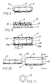
- FIGURE 8 is a representative view of an aspect of assembling the embodiment of FIGURE 1 using an exemplary arbor press. Parts are broken away.
- FIGURE 9 is a representative view of a vessel of lubricant and a sleeve or vial to be dipped in such lubricant.
- FIGURE 10 is a side elevation view of an aspect of assembling the embodiment of FIGURE 1 using a described abutment member.
- FIGURE 11 is an elevation view of the abutment member taken along the viewing plane 11-11 of FIGURE 10. Surfaces are shown in dashed outline and parts are broken away.
- FIGURE 12 is an elevation view of a carpenter or builder's level incorporating the inventive vial assembly. Parts are broken away.
-
- Referring to FIGURES 1 through 6, the new
liquid vial assembly 10 comprises a liquid-containingvial 11 having a seamless, generally-cylindrical wall 13, i.e., awall 13 formed as a unitary structure unbroken by joints, abutments or the like along its length. Such wall 13 (together with any end plugs 15 or the like) confines the liquid 17 (and the bubble 19) used for determining whether, e.g., a floor is horizontal or a wall is vertical. - A transparent
outer sleeve 21 extends along thewall 13 and the resistance of thevial 11 to breakage is thereby improved bysuch sleeve 21. In the embodiment of FIGURES 1-3, theouter sleeve 21 is resilient (and slightly stretched when on the vial 11). - Referring particularly to FIGURE 3, certain embodiments of the
assembly 10 involve dimensional relationships. Specifically, thesleeve 21 has aninterior passage 23 with a first diameter D1, the vialcylindrical wall 13 has an outer second diameter D2. In the instance of aresilient sleeve 21 in its non-stretched or "repose" state, the first diameter D1 is not greater than the second diameter D2. Most preferably, such first diameter D1 is less than such second diameter D2. - A preferred resilient
outer sleeve 21 has a hardness in the range of 60 to 100 as measured on the Shore A scale and, more preferably, a hardness in the range of 75 to 85 on such scale. An ideal material for aresilient sleeve 21 is polyvinyl chloride tubing or polyurethane. - In another aspect of the invention, the
resilient sleeve 21 is stretched around the wall. In other words,such sleeve 21 is in tension about its circumference. Because thesleeve 21 "grips" thevial 11 very firmly, thesleeve 21 and thevial 11 are tightly secured to one another. - Referring particularly to FIGURE 1, in yet another aspect of the invention, the vial
cylindrical wall 11 has an outside diameter D2, theentire assembly 10 has an outside diameter D3 and the outside diameter D3 of the assembly is at least about 1.03 times the outside diameter D2 of thecylindrical wall 13. More preferably, the outside diameter D3 of theassembly 10 is in the range of about 1.3 to 1.8 times the outside diameter D2 of thecylindrical wall 13. In an exemplary, very specific embodiment, the outside diameter D2 of thevial wall 13 is about 0.947 cm (0.373 inches) and whensuch sleeve 21 is in its "unstretched" or repose state, its inside diameter D1 is about 0.914 cm (0.360 inches). When thevial 11 andsleeve 21 are assembled, the sleeve outside diameter D3 is about 1.397 cm (0.550 inches) or slightly less. - With a cylindrical sleeve 21 (resilient as in FIGURES 1 and 2), there is very-apparent magnification of both the
reference lines 25 around the outer circumference of thevial 11 and thebubble 19 in thevial 11 so that the relationship of thebubble 19 to thelines 25 is easier to see. Such magnification is apparent by comparing FIGURES 1 and 2. In another embodiment of FIGURES 4 and 5, theouter sleeve 21 is generally rectangular in cross-section, e.g., square, and thereference lines 25 and thebubble 19 are more greatly magnified for easier viewing. (It is to be understood that FIGURES 4 and 5 represent avial assembly 10 having arectangular sleeve 21 which is resilient.) - Referring particularly to FIGURES 6 and 7, in the embodiment of the
assembly 10 involving a rigidouter sleeve 21, there is a liquid 27 between the vialcylindrical wall 13 andsuch sleeve 21. The reason for such liquid 27 is as follows. - It is extremely difficult (with manufacturing procedures of reasonable cost consistent with the selling prices of carpenter's levels) to hold tolerances on vial outside diameter and sleeve inside diameter to the "tightness" needed to eliminate what would otherwise appear to be a line between the
sleeve 21 andvial 11. Providing a liquid 27 between thesleeve 21 andvial 11 eliminates such visually-apparent line or at least dramatically reduces its prominence.Liquids 27 suitable for use in the above-described embodiment include mineral oil, silicone fluid and glycerine or other liquids having similar viscosity, resistance to evaporation and chemical compatibility with the material(s) from which thevial 11 andsleeve 21 are made. - In those embodiments of the
assembly 10 having a liquid 27 between thevial 11 and thesleeve 21, it is preferable to use a liquid-sealingmember 29 extending between thecylindrical wall 13 and theouter sleeve 21.Appropriate sealing members 29 includeepoxy resin 29a andelastomeric seals 29b, as examples. - In another aspect of the breakage-
resistant assembly 10, the vialcylindrical wall 13 is made of a first material and theouter sleeve 21 is made of a second material which is substantially non-shatterable. Where resilience is desired, such second material may be polyvinyl chloride or another material having similar physical properties. Apreferred sleeve 21 made of such relatively-hard material has a hardness in the range of 75-100 and, most preferably, in the range of 90-95, both measured on the Rockwell M scale. - Referring next to FIGURES 8 and 9, the invention also involves a new method for making an encapsulated
level vial assembly 10. FIGURE 9 depicts the top and bottom platens of an arbor press, an exemplary machine useful in the method. The top platen 31 has a counterboredpocket 37 while thebottom platen 33 has counterboredpockets pocket 39 is sized to receive anend 43 of thesleeve 21 with slight clearance. Similarly, thepockets vial 11 with slight clearance. - When an
end 43 of thesleeve 21 is placed in thepocket 39 as shown,such end 43 is sealed. Air inside thesleeve 21 is substantially prevented from escaping from thatend 43, at least to the degree needed to pressurize the air as described below. - The
vial 11 andsleeve 21 are urged together by moving the top platen 31 toward thebottom platen 33. After initial insertion, thevial 11 seals theother end 49 of thesleeve 21, the pressure of the air trapped in thesleeve 21 increases and thesleeve 21 stretches somewhat as represented by the dashed lines 51. - It is to be understood that the method may be carried out by reversing the positions of the
vial 11 andsleeve 21 from those shown in FIGURE 8 and, with appropriately-configuredpockets appropriate platens 31, 33, urging thesleeve 21 downward onto thevial 11. And of course, higher-production "clamp-like" tooling and equipment (whether oriented vertically, horizontally or at some other angle) may be used for urgingsleeve 21 andvial 11 together. - Referring next to FIGURE 10, the
vial 11 andsleeve 21 may also be assembled by providing a generally-cylindrical liquid-containingvial 11, providing asleeve 21 having afirst end 53 and asecond end 55 and restraining the sleevefirst end 53. Thevial 11 is urged into thesecond end 55 of thesleeve 21. - More specifically, the restraining step includes placing an
abutment member 57 against thefirst end 53 in a manner to permit air to escape from the sleeveinterior passage 23. Possible "shaving" of the wall defining the sleeveinterior passage 23 may be avoided by slightly chamfering theend edge 59 of thevial 11. And in the case of aresilient sleeve 21, it may be desirable or even necessary to placesuch sleeve 21 in a tube-like fixture 61 to help prevent bending or buckling. Asuitable abutment member 57 is shown in FIGURE 11. - If the
vial 11 andsleeve 21 evidence some "sticktion" when being urged together, alubricant 63 may be provided betweensuch vial 11 andsleeve 21. Ways to providesuch lubricant 63 include dipping thesleeve 21 in alubricant 63 as shown in FIGURE 9 and/or dipping thevial 11 in alubricant 63, or otherwise applying thelubricant 63 to thesleeve 21 and/or to thevial 11. Alubricant 63 comprising a few drops of dishwashing detergent mixed with, say, one-half cup of water is very satisfactory. - A variant of the preferred method for making an encapsulated
level vial assembly 10 having ahard sleeve 21 includes the steps of providing a liquid-containingvial 11, providing asleeve 21, applying a liquid 27 to thevial 11, to thesleeve 21 or to both and urging thevial 11 andsleeve 21 together. The liquid may be provided between thevial 11 and thesleeve 21 aftersuch vial 11 andsleeve 21 are assembled. - Such liquid 27 may be provided between the
vial 11 and thesleeve 21 by differential pressure between the sleeve ends 53, 55. For example, the liquid 27 may be drawn or "sucked" into oneend sleeve 21 by immersing thatend end seal member 29 is used between the vial .11 and thesleeve 21 for liquid retention. - FIGURE 12 shows a builder's level 65 equipped with the
new vial assembly 10. - To provide an understanding of the dramatic improvement in vial breakage resistance resulting from the invention, it was found that an object dropped from a particular height had enough energy to fracture an
unprotected vial 11. When thevial 11 is encapsulated with aresilient sleeve 21, the same object had to be dropped from a height that was over seven times greater to experience vial fracturing. - The encapsulated
vial assembly 10 involves a new mode of construction and affords the user new properties not heretofore available in level vials. Theassembly 10 represents the first practical, easy-to-make, easy-to-mount success in the field of builder's levels.
Claims (10)
- A liquid vial assembly (10) comprising:characterized in thata liquid-containing vial (11) having a seamless cylindrical wall (13)a transparent outer sleeve (21) extending along the wall (13), wherein substantially the entirety of the vial (11) is visible through the sleeve (21),the cylindrical wall is made of plastic material,the sleeve (21) is slightly stretched around the wall (13) and is made of resilient material andthe sleeve (21) has ends which are open and free of seals.
- The vial assembly of claim 1 further including a liquid (27) between the cylindrical wall (13) and the outer sleeve (21).
- The vial assembly of claim 2 wherein the liquid (27) is selected from mineral oil, silicone fluid or glycerine.
- The vial assembly of claim 1 wherein the sleeve (21) is made of resilient material having a hardness in the range of 60 to 100 as measured on the Shore A scale.
- The vial assembly of claim 1 further characterized in that:the vial (11) has reference lines (25) thereon and a bubble (19) within;the outer sleeve (21) is generally rectangular in cross-section and has rounded edges therealong; andthe outer sleeve (21) is in contact with the vial (11) along substantially the entire length of the sleeve (21).
- The vial assembly according to any one of claims 1 to 5 characterized in that:the cylindrical walls (13) has an outside diameter (D2);the assembly (10) has an outside diameter (D3); andthe outside diameter (D3) of the assembly (10) is in the range of about 1.5 to 1.8 times the outside diameter (D2) of the cylindrical wall (13).
- The vial assembly according to any one of claim 1 to 6 wherein the sleeve (21) is made of polyvinyl chloride or polyurethane.
- A method for making an encapsulated level vial including the steps of:providing a liquid-containing vial;providing a sleeve made of resilient material;providing a lubricant for permitting the vial and the sleeve to easily slide with respect to one another; andurging the vial and sleeve together while pressurizing the sleeve interior, thereby slightly stretching the sleeve.
- The method of claim 8 wherein the lubricant-providing step includes dipping the vial in the lubricant.
- The method of claim 8 wherein the lubricant-providing step includes dipping the sleeve in the lubricant.
Applications Claiming Priority (2)
| Application Number | Priority Date | Filing Date | Title |
|---|---|---|---|
| US08/397,430 US5588217A (en) | 1995-03-01 | 1995-03-01 | Level vial assembly with encapsulated vial |
| US397430 | 1995-03-01 |
Publications (2)
| Publication Number | Publication Date |
|---|---|
| EP0730136A1 EP0730136A1 (en) | 1996-09-04 |
| EP0730136B1 true EP0730136B1 (en) | 2002-06-26 |
Family
ID=23571170
Family Applications (1)
| Application Number | Title | Priority Date | Filing Date |
|---|---|---|---|
| EP96103126A Expired - Lifetime EP0730136B1 (en) | 1995-03-01 | 1996-03-01 | Level vial assembly with encapsulated vial |
Country Status (3)
| Country | Link |
|---|---|
| US (1) | US5588217A (en) |
| EP (1) | EP0730136B1 (en) |
| DE (1) | DE69621966T2 (en) |
Families Citing this family (17)
| Publication number | Priority date | Publication date | Assignee | Title |
|---|---|---|---|---|
| IL123586A (en) | 1998-03-06 | 2001-04-30 | Karpo Ind Ltd | Spirit level with hand grips |
| US6138369A (en) * | 1998-04-08 | 2000-10-31 | Mushin; Uriel | Level indicator for a wall-mounted fixture |
| DE29814656U1 (en) * | 1998-08-14 | 1999-12-23 | Stabila-Messgeräte Gustav Ullrich GmbH & Co KG, 76855 Annweiler | Spirit level |
| US6205669B1 (en) * | 1999-02-04 | 2001-03-27 | Dennis R. Sollars | Wall hanging level |
| US6735880B1 (en) | 1999-11-22 | 2004-05-18 | Great Neck Saw Manufacturers, Inc. | Vial and method of making same |
| US6434842B1 (en) | 2000-08-13 | 2002-08-20 | Rasping Level Technology Inc. | Rasping level |
| US6915586B2 (en) | 2003-08-18 | 2005-07-12 | Empire Level Mfg. Corp. | Box level |
| US7086167B2 (en) * | 2004-04-16 | 2006-08-08 | Empire Level Mfg. Corp. | Overmolded vial for use with a level |
| GB0500906D0 (en) | 2005-01-17 | 2005-02-23 | Dupont Teijin Films Us Ltd | Coextruded polymeric film |
| US7603961B2 (en) * | 2006-05-15 | 2009-10-20 | Danny Mayenschein | Lighted orientation device |
| US7472487B2 (en) * | 2006-05-26 | 2009-01-06 | The Stanley Works | Level |
| DE202009016443U1 (en) * | 2009-12-04 | 2011-04-14 | Bayerische Maß-Industrie Arno Keller GmbH | Spirit level made of a wood-plastic composite material |
| IL224928A0 (en) | 2013-02-26 | 2013-07-31 | Kapro Ind Ltd | Spirit level |
| US9170104B2 (en) | 2013-12-16 | 2015-10-27 | Stanley Black & Decker, Inc. | Level vial and method of manufacturing same |
| USD730207S1 (en) | 2014-03-05 | 2015-05-26 | Kapro Industries Ltd. | Spirit level |
| USD750984S1 (en) | 2014-09-30 | 2016-03-08 | Kapro Industries Ltd. | Box spirit level with ruler |
| USD805928S1 (en) | 2016-09-21 | 2017-12-26 | Kapro Industries Ltd. | Stud layout level |
Family Cites Families (19)
| Publication number | Priority date | Publication date | Assignee | Title |
|---|---|---|---|---|
| US3311990A (en) * | 1967-04-04 | Edward j. brenner | ||
| US2755561A (en) * | 1956-07-24 | hqlnjaah | ||
| US784418A (en) * | 1901-05-13 | 1905-03-07 | Henry N Northoff | Spirit-level. |
| US1291230A (en) * | 1917-11-24 | 1919-01-14 | Frederick Stitzel | Indicator. |
| US1384062A (en) * | 1919-05-19 | 1921-07-12 | Happle John | Level |
| US1578786A (en) * | 1923-08-20 | 1926-03-30 | E R Watts & Son Ltd | Spirit level |
| US1614814A (en) * | 1923-09-26 | 1927-01-18 | Adolph D Willson | Gradometer |
| US1654248A (en) * | 1925-05-16 | 1927-12-27 | Erdmann Friedrich | Illuminated level |
| US1622752A (en) * | 1926-05-05 | 1927-03-29 | George J Yakesh | Inclination indicator |
| US2102364A (en) * | 1935-12-23 | 1937-12-14 | Dietzgen Eugene Co | Spirit level and means for mounting same |
| US2221912A (en) * | 1939-11-13 | 1940-11-19 | Bausch & Lomb | Liquid level |
| FR1147312A (en) * | 1956-04-09 | 1957-11-21 | Unbreakable vial improved for levels and similar devices | |
| GB1001771A (en) * | 1963-05-01 | 1965-08-18 | Saunders Roe & Nuclear Entpr | Improvements in or relating to the illumination of levelling bubbles |
| US3871109A (en) * | 1973-03-12 | 1975-03-18 | Peter P Vaida | Level vial |
| US4085515A (en) * | 1977-01-17 | 1978-04-25 | Darden Donald R | Alignment device |
| FR2449868A1 (en) * | 1979-02-26 | 1980-09-19 | Stanley Mabo | Glass bubble tube for spirit level - with sleeve at PMMA or ABS sealed at ends by friction welding |
| DE3407583A1 (en) * | 1984-03-01 | 1984-10-04 | Werner 8401 Graßlfing Krieger | Unbreakable spirit level |
| JPS60232502A (en) * | 1984-05-04 | 1985-11-19 | Tokyo Optical Co Ltd | Liquid prism |
| DE4014638A1 (en) * | 1990-05-08 | 1991-11-14 | Bayerische Massindustrie Arno | DRAGONFLY FOR LEVELS |
-
1995
- 1995-03-01 US US08/397,430 patent/US5588217A/en not_active Expired - Lifetime
-
1996
- 1996-03-01 EP EP96103126A patent/EP0730136B1/en not_active Expired - Lifetime
- 1996-03-01 DE DE69621966T patent/DE69621966T2/en not_active Expired - Fee Related
Also Published As
| Publication number | Publication date |
|---|---|
| US5588217A (en) | 1996-12-31 |
| DE69621966D1 (en) | 2002-08-01 |
| DE69621966T2 (en) | 2003-03-27 |
| EP0730136A1 (en) | 1996-09-04 |
Similar Documents
| Publication | Publication Date | Title |
|---|---|---|
| US5588217A (en) | Level vial assembly with encapsulated vial | |
| US3311990A (en) | Edward j. brenner | |
| JP5089379B2 (en) | Bubble tube with dark band used in spirit level | |
| EP2316000B1 (en) | Spirit level having horizontal bubble vial with improved bubble visibility | |
| US11506491B2 (en) | Vial with improved visibility for level | |
| CA2138235A1 (en) | Optical liquid level sensor and discriminator | |
| US8011109B2 (en) | Casing mount for a cylindrical vial | |
| WO2003039969A3 (en) | Packaging for contact lenses | |
| US3673696A (en) | Attitude indicator | |
| EP0129388A3 (en) | Measurement of contact lenses | |
| MXPA05013852A (en) | Structure and method for holding and protecting vials in levels. | |
| FR2715133B1 (en) | Container with a flexible deformable wall, of the vial, pocket or tube type, and method of manufacturing such a container. | |
| US5309645A (en) | Combination plumb or level and height setting instruments | |
| US20060254066A1 (en) | Level-determining adhesive patch | |
| GB2287534A (en) | Adjustable spirit level | |
| US3583073A (en) | Level vial construction | |
| GB2348953A (en) | Spirit level device | |
| JP2002181707A (en) | Mirror cylinder for measuring transparency of pool water and transparency measuring kit | |
| KR920001888Y1 (en) | Bubble protecting apparatus of water meter | |
| CN215639427U (en) | Plane level | |
| CN219046151U (en) | Mutually clamped optical lens | |
| WO2009136947A1 (en) | Level | |
| EP3264037A1 (en) | Vial for spirit level | |
| CN214621154U (en) | Scaffold safety inspection device | |
| ITMI920372A1 (en) | FILLING VALVE DEVICE FOR NON GASATED LIQUIDS WORKING FOR GRAVITY, WITH SELF-LEVELING SYSTEM AT LIGHT GAS PRESSURE, FOR BOTTLING MACHINES |
Legal Events
| Date | Code | Title | Description |
|---|---|---|---|
| PUAI | Public reference made under article 153(3) epc to a published international application that has entered the european phase |
Free format text: ORIGINAL CODE: 0009012 |
|
| AK | Designated contracting states |
Kind code of ref document: A1 Designated state(s): DE FR GB |
|
| 17P | Request for examination filed |
Effective date: 19961213 |
|
| 17Q | First examination report despatched |
Effective date: 19990527 |
|
| GRAG | Despatch of communication of intention to grant |
Free format text: ORIGINAL CODE: EPIDOS AGRA |
|
| GRAG | Despatch of communication of intention to grant |
Free format text: ORIGINAL CODE: EPIDOS AGRA |
|
| GRAH | Despatch of communication of intention to grant a patent |
Free format text: ORIGINAL CODE: EPIDOS IGRA |
|
| GRAH | Despatch of communication of intention to grant a patent |
Free format text: ORIGINAL CODE: EPIDOS IGRA |
|
| GRAH | Despatch of communication of intention to grant a patent |
Free format text: ORIGINAL CODE: EPIDOS IGRA |
|
| GRAA | (expected) grant |
Free format text: ORIGINAL CODE: 0009210 |
|
| AK | Designated contracting states |
Kind code of ref document: B1 Designated state(s): DE FR GB |
|
| REG | Reference to a national code |
Ref country code: GB Ref legal event code: FG4D |
|
| REF | Corresponds to: |
Ref document number: 69621966 Country of ref document: DE Date of ref document: 20020801 |
|
| ET | Fr: translation filed | ||
| PLBE | No opposition filed within time limit |
Free format text: ORIGINAL CODE: 0009261 |
|
| STAA | Information on the status of an ep patent application or granted ep patent |
Free format text: STATUS: NO OPPOSITION FILED WITHIN TIME LIMIT |
|
| 26N | No opposition filed |
Effective date: 20030327 |
|
| PGFP | Annual fee paid to national office [announced via postgrant information from national office to epo] |
Ref country code: GB Payment date: 20040225 Year of fee payment: 9 |
|
| PGFP | Annual fee paid to national office [announced via postgrant information from national office to epo] |
Ref country code: FR Payment date: 20040309 Year of fee payment: 9 |
|
| PGFP | Annual fee paid to national office [announced via postgrant information from national office to epo] |
Ref country code: DE Payment date: 20040311 Year of fee payment: 9 |
|
| PG25 | Lapsed in a contracting state [announced via postgrant information from national office to epo] |
Ref country code: GB Free format text: LAPSE BECAUSE OF NON-PAYMENT OF DUE FEES Effective date: 20050301 |
|
| PG25 | Lapsed in a contracting state [announced via postgrant information from national office to epo] |
Ref country code: DE Free format text: LAPSE BECAUSE OF NON-PAYMENT OF DUE FEES Effective date: 20051001 |
|
| GBPC | Gb: european patent ceased through non-payment of renewal fee |
Effective date: 20050301 |
|
| PG25 | Lapsed in a contracting state [announced via postgrant information from national office to epo] |
Ref country code: FR Free format text: LAPSE BECAUSE OF NON-PAYMENT OF DUE FEES Effective date: 20051130 |
|
| REG | Reference to a national code |
Ref country code: FR Ref legal event code: ST Effective date: 20051130 |