EP0728227B1 - Dispositif de compensation de tension alternative entre un milieu et un pipeline metallique dispose dans celui-ci - Google Patents
Dispositif de compensation de tension alternative entre un milieu et un pipeline metallique dispose dans celui-ci Download PDFInfo
- Publication number
- EP0728227B1 EP0728227B1 EP93905736A EP93905736A EP0728227B1 EP 0728227 B1 EP0728227 B1 EP 0728227B1 EP 93905736 A EP93905736 A EP 93905736A EP 93905736 A EP93905736 A EP 93905736A EP 0728227 B1 EP0728227 B1 EP 0728227B1
- Authority
- EP
- European Patent Office
- Prior art keywords
- voltage
- pipeline
- induced
- phase position
- transformer
- Prior art date
- Legal status (The legal status is an assumption and is not a legal conclusion. Google has not performed a legal analysis and makes no representation as to the accuracy of the status listed.)
- Expired - Lifetime
Links
Images


Classifications
-
- C—CHEMISTRY; METALLURGY
- C23—COATING METALLIC MATERIAL; COATING MATERIAL WITH METALLIC MATERIAL; CHEMICAL SURFACE TREATMENT; DIFFUSION TREATMENT OF METALLIC MATERIAL; COATING BY VACUUM EVAPORATION, BY SPUTTERING, BY ION IMPLANTATION OR BY CHEMICAL VAPOUR DEPOSITION, IN GENERAL; INHIBITING CORROSION OF METALLIC MATERIAL OR INCRUSTATION IN GENERAL
- C23F—NON-MECHANICAL REMOVAL OF METALLIC MATERIAL FROM SURFACE; INHIBITING CORROSION OF METALLIC MATERIAL OR INCRUSTATION IN GENERAL; MULTI-STEP PROCESSES FOR SURFACE TREATMENT OF METALLIC MATERIAL INVOLVING AT LEAST ONE PROCESS PROVIDED FOR IN CLASS C23 AND AT LEAST ONE PROCESS COVERED BY SUBCLASS C21D OR C22F OR CLASS C25
- C23F13/00—Inhibiting corrosion of metals by anodic or cathodic protection
Definitions
- the invention relates to a device for compensation of an alternating voltage which occurs between a medium and a metallic pipeline disposed in the medium, the pipeline being surrounded by a layer (mantle) of electrically insulating material.
- the normal operating current of the transmission line induces a voltage in the metal pipe.
- a voltage in the metal pipe For example, from a 400 kV line with an operating current of 1000 A at a distance of 50 m from the pipeline, an induced voltage of about 20 V/km can be obtained.
- a metal pipe of the above kind may, for example, constitute part of a long gas conduit, which is disposed in the ground and possibly partially also in water.
- a conduit of this kind is usually divided into sections with the aid of electrically insulating joints. The length of one section may vary from several kilometres up to several tens of kilometres. If a transmission line runs parallel to such a line for a distance of some length, induced voltages of a considerable magnitude may therefore occur.
- the invention as defined in claim 1 aims to provide a device which, in a simple and advantageous manner, provides good protection against the risks of corrosion which, in pipelines of the kind mentioned in the introduction, are caused by alternating voltages induced in the pipelines.
- Preferred embodiments are defined in the dependent claims 2-10.
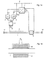
- Figure 1a shows an elementary diagram of a piece of equipment according to the invention.
- the figure shows a section 1 of a metallic natural gas conduit 1 disposed in the ground, the conduit being provided with an electrically insulating coating and being electrically insulated from adjoining pipe sections with the aid of electrically insulating joints 11 and 12.
- a measuring conductor 2 insulated from ground is arranged. This conductor may be arranged in the ground, on the ground or above the ground.
- the measuring conductor 2 is suitably arranged parallel to the pipeline and close to this.
- the length of the measuring conductor may be small in relation to the length of the section 1, but if desirable for obtaining a sufficient magnitude of the measured signal from the conductor, the length of the conductor may constitute a considerable part of the length of the section.
- the conductor 2 may be grounded at a suitable point.
- the voltage u s induced in the conductor 2 is supplied to an instrumentation amplifier 3, the output signal of which is designated u' s . Due to the location of the measuring conductor 2 parallel to and close to the pipe section 1, the signals u s and u' s become a good measure of the voltage induced in the pipe section by the operating current of the transmission line.
- the signal u' s from the instrumentation amplifier 3 is supplied to an absolute value generator 4 and a phase detector 5.
- the absolute value generator 4 delivers a signal U which is proportional to the amplitude of the voltage u s induced in the measuring conductor 2.
- the phase detector 5 delivers a signal ⁇ which is proportional to the phase difference between the signal u' s and a reference voltage u ref .
- the reference signal is an alternating signal with the same frequency as the frequency in the transmission line which causes the voltages induced in the pipeline. As shown in the figure, the reference voltage can be obtained in the simplest manner from a local network 6, which belongs to the same power network as the above-mentioned transmission line and therefore has the same frequency as this.
- the signals U and ⁇ are supplied to a controller 7, which is adapted to supply an alternating voltage U 1 with controllable amplitude and with controllable phase position.
- the controller 7 may consist of an alternating voltage converter, for example an intermediate link converter with a controllable rectifier supplied from the network 6, a direct voltage intermediate link, and a self-commutated inverter adapted to supply an alternating voltage with controllable frequency and hence with controllable phase position.
- the voltage U is adapted to control the intermediate link direct voltage and hence the amplitude of the voltage U 1
- the voltage U 1 generated by the controller 7 is supplied to a transformer 8.
- this transformer has an iron core 81 with an annular or rectangular cross section, which surrounds the pipeline 1.
- the iron core is suitably made of oriented sheet metal and can be made wound from one single coherent strip of sheet.
- the core may consist of a number of composite sheets with their planes perpendicular to the longitudinal axis of the pipeline.
- a primary winding 82 is applied on the core, the voltage U 1 from the controller 7 being connected to this primary winding.
- the winding 82 and the controller 7 are designed such that suitable current and voltage levels are obtained.
- the winding 82 may consist of ten turns, the voltage U 1 have a root-mean square (RMS) value of the order of magnitude of 100 V, and the current through the primary winding of the transformer have an RMS of about 13 A.
- RMS root-mean square
- this EMF is in phase opposition to the EMF induced in the pipeline by the transmission line.
- the constant k in the expression above is chosen and adjusted in the control system such that the desired degree of suppression is obtained of the voltage induced in the pipeline.
- the constant k can be determined by calculation, measurement or by practical tests.
- the signal from the measuring conductor 2 can be filtered in a band-pass filter tuned to the frequency of the transmission line, this in order to eliminate the effect of voltages occurring in the measuring conductor and emanating from other sources than the transmission line.
- Figure 1c shows the voltage in the pipeline in relation to ground plotted against the distance x from one end of the line section.
- the section is assumed to have the length 1 and be grounded at its centre, for example through damage to the electrical insulation of the line.
- the curve designated a in the figure shows the voltage which would be caused by a transmission line extending in parallel with the line section along the whole of its length.
- the voltage assumes a maximum value ⁇ u m at the end points of the section. If a transformer 8 according to the invention is arranged at the centre of the line section and adapted to induce in the pipeline an EMF of the magnitude u m , the voltage will have an appearance as shown by the curve b.
- the maximum voltage between the pipeline and ground is reduced by a factor 2.
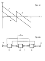
- FIG. 2a shows such an example where three transformers 8a, 8b and 8c are arranged evenly distributed along the length of the section. The primary windings of the transformers are connected in parallel to the controller 7 and are thus supplied with the voltage U 1 .
- the curve c shows the voltage which is obtained between the pipeline and ground. As is clear, in this case a reduction of the maximum voltage by a factor of 4 is obtained.
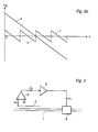
- Figure 3 shows an alternative embodiment of the equipment according to the invention.
- the signal u' s from the instrumentation amplifier 3 is supplied to a sign-reversing power amplifier 9, the output signal U 1 of which is supplied to the transformer 8.
- the signal U 1 will be in phase opposition to the signal u' s and by a suitable adjustment of the amplification factor of the amplifier, in principle a complete suppression of the voltages induced in the pipeline 1 can be obtained.
- the amplifier 9 may, for example, be a switched power amplifier of a kind known per se.
- FIG 4 shows how, as an alternative, a transformer coupling can be used for generating the supply voltage to the transformer 8.
- the coupling comprises two single-phase transformers 22 and 23.
- the transformer 22 has its primary winding connected to the phases S and T of the local network 6, and the transformer 23 has its primary winding connected between the phase R and the neutral line 0 of the network.
- the amplitude of the output voltage of each transformer is controllable, continuously or in steps.
- the transformers may, for example, consist of servo-motor operated adjustable transformers or of transformers which are provided with tap changers.
- the output voltage U A from the transformer 23 will have a phase shift of 90° in relation to the output voltage U B from the transformer 22.
- the output voltage U 1 may in a known manner be controlled arbitrarily both with respect to amplitude and phase position within all four quadrants.
- the signals U and ⁇ are supplied to a control unit 21, which delivers control signals s1 and s2 to the actuators of the transformers.
- the control device may, for example, deliver such control signals sl and s2 to the transformers that the output voltages thereof become:
- U A Usin( ⁇ + ⁇ )
- U A Ucos( ⁇ + ⁇ )
- the supply voltage to the transformer 8 will have the amplitude U and a phase position which is in opposition to the alternating voltage induced in the pipeline 1.
- the control of the equipment according to the invention can be carried out in other ways than the one described above.
- the voltage between the pipeline and ground may be sensed at one or a plurality of points distributed along the pipeline.
- this is done by connecting instrumentation amplifiers 31, 32, 33 between ground and the points P12, P2, P3 on the pipeline.
- the output signals u' s1 , u' s2 , u' s3 of the instrumentation amplifier are supplied to an optimization unit 34 (Fig. 5b).
- This delivers a control signal s3 to the controller 7.
- the control signal s3 influences the amplitude and phase position of the voltage U 1 generated by the controller, which voltage is supplied to the transformer 8.
- the optimization unit 34 may, for example, consist of a suitably programmed computer adapted to influence the voltage U 1 via the control signal s3 in such a way in dependence on the measured signals that the risk of corrosion of the pipeline is minimized.
- the optimization unit may, for example, form the mean value of the measured signals and by successive attempts vary the amplitude and phase position of the voltage U 1 until this mean value reaches a minimum.
- the mean value of the measured signals as described above, it is, of course, possible to form and minimize some other quantity representative of the risk of corrosion.
- the quantity which is minimized can consist of that of the measured signals which has the greatest absolute value.
- the input signal or signals to the optimization unit 34 in Figure 5b need not, of course, be formed in the manner shown in Figure 5a.
- the input signals to the optimization unit may consist of the measured signal or signals from one or more measuring conductors 2 of the kind shown in Figure 1.
- Figure 2a shows how several transformers, supplied from a common voltage source, can be disposed along the pipeline section in question to achieve a greater reduction of the induced voltages.
- the same effect can be attained by placing several complete pieces of equipment of the kind shown in Figure la along the pipeline section.
- the measuring conductors 2 shown in Figures 1 and 3 constitute one way of forming a quantity which is a measure of the voltage induced in the pipeline. Also other ways are feasible. As mentioned, the voltage induced in the pipeline is, with respect to magnitude and phase position, directly dependent on the load current of the transmission line. Where it is possible and suitable to measure this current, it can be used directly as a measure of the voltage induced in the pipeline.
- the load current in the transmission line and hence the voltage induced in the pipeline, is a pure sine wave current without harmonics.
- harmonics may occur in the load current and induce alternating voltages of corresponding frequencies in the pipeline, which voltages, in the same way as the fundamental component, may cause risks of corrosion.
- the embodiment of the invention shown in Figure 3 will automatically entail a compensation also of induced harmonics, since the voltage U 1 applied to the transformer constitutes a sign-reversed reproduction of the measured signal u s obtained from the measuring conductor 2. Harmonics in the induced voltage may, of course, be compensated for also in other ways.
- both the fundamental component and the harmonics in question may be separated out of the measured signal with the aid of the band-pass filter and be determined individually in amplitude and phase position, whereupon the desired voltage U 1 for suppressing all the sensed components are synthetized in a suitable way with the aid of suitable electronic circuits.
- a cascade connection of an induction regulator and an adjustable transformer can be used, the induction regulator being used for controlling the phase position of the supply voltage to the transformer 8 and the adjustable transformer being used for controlling the amplitude of the voltage.
Landscapes
- Chemical & Material Sciences (AREA)
- Engineering & Computer Science (AREA)
- Materials Engineering (AREA)
- Mechanical Engineering (AREA)
- Metallurgy (AREA)
- Organic Chemistry (AREA)
- Pipeline Systems (AREA)
- Investigating Or Analyzing Materials By The Use Of Magnetic Means (AREA)
- Water Treatment By Electricity Or Magnetism (AREA)
- Testing Resistance To Weather, Investigating Materials By Mechanical Methods (AREA)
- Pinball Game Machines (AREA)
- Surgical Instruments (AREA)
- Massaging Devices (AREA)
- General Induction Heating (AREA)
Claims (10)
- Dispositif destiné à compenser une tension alternative qui apparaît entre un milieu et un pipe-line (1) métallique disposé dans le milieu, le pipe-line étant entouré par une couche ou une enveloppe de matériau isolant électriquement, caractérisé en ce que le dispositif comprend :a) un transformateur (8) ayant un noyau (81) qui, en utilisation, entoure le pipe-line et ayant un enroulement (82) appliqué sur le noyau,b) des premiers éléments (2, 3, 4, 5) adaptés pour former une quantité (U, ϕ) qui correspond à la tension alternative apparaissant dans le pipe-line, etc) des éléments (7) produisant une tension adaptés pour recevoir la quantité, pour produire, en fonction de celle-ci une tension (U1) alternative et pour alimenter en cette tension l'enroulement de transformateur d'une telle manière qu'en utilisation, la tension entre le milieu et le pipe-line est influencée pour réduire le risque de corrosion du pipe-line.
- Dispositif suivant la revendication 1, caractérisé en ce que les premiers éléments comportent un conducteur (2) de mesure qui en utilisation est disposé sensiblement parallèlement au pipe-line, et en ce que ladite quantité est formée à partir de la tension (us) induite dans le conducteur de mesure.
- Dispositif suivant la revendication 2, caractérisé en ce que les premiers éléments comportent des éléments (4) détecteurs d'amplitude adaptés pour former un signal (U) d'amplitude correspondant à l'amplitude de la tension induite, ainsi que des éléments (5) de détection d'angle de phase adaptés pour former un signal (ϕ) de position de phase correspondant à la position de phase de la tension induite, ces signaux étant adaptés pour être envoyés à l'élément (7) produisant une tension, qui à son tour est adapté pour produire et alimenter le transformateur (8) en une tension (U1) ayant une amplitude correspondant au signal d'amplitude et une position de phase correspondant au signal de position de phase.
- Dispositif suivant la revendication 3, caractérisé en ce que les éléments (5) capteurs d'angle de phase sont adaptés pour former le signal de position de phase en fonction de la position de phase de la tension induite dans le conducteur de mesure par rapport à une tension (Uref) alternative de référence, et en ce que l'élément (7) produisant une tension est adapté pour produire une tension (U1) alternative ayant la même fréquence que la tension de référence et ayant une position de phase, par rapport au signal (Uref) de référence qui est dépendante du signal (ϕ) de position de phase.
- Dispositif suivant la revendication 1, caractérisé en ce que les premiers éléments comportent des éléments (31, 32, 33, 34) adaptés pour détecter la tension entre le pipe-line et le milieu environnant en un ou en plusieurs des points (P1, P2, P3) le long du pipe-line et, en fonction des valeurs (u's1, u's2, u's3) détectées, destinés à former une quantité (s3) de commande destinée à commander l'élément (7) produisant la tension.
- Dispositif suivant l'une quelconque des revendications précédentes, caractérisé en ce qu'il comporte une pluralité de transformateurs (8a, 8b, 8c) qui en utilisation sont répartis le long du pipe-line.
- Dispositif suivant la revendication 6, caractérisé en ce que les transformateurs sont alimentés par une source (7) de tension commune.
- Dispositif suivant l'une quelconque des revendications précédentes, caractérisé en ce que les éléments (9) producteurs de tension sont constitués d'un amplificateur de puissance.
- Dispositif suivant l'une quelconque des revendications 1 à 7, caractérisé en ce que les éléments (7) produisant une tension sont constitués d'un couplage de convertisseur statique.
- Dispositif suivant l'une quelconque des revendications 1 à 7, caractérisé en ce que l'élément (21, 22, 23) producteur de tension est constitué d'un couplage (21, 22, 23) transformateur pouvant être commandé.
Applications Claiming Priority (3)
| Application Number | Priority Date | Filing Date | Title |
|---|---|---|---|
| SE9200671 | 1992-03-05 | ||
| SE9200671A SE469987B (sv) | 1992-03-05 | 1992-03-05 | Anordning för kompensering av en växelspänning som uppträder mellan ett medium och en i mediet förlagd metallisk rörledning |
| PCT/SE1993/000187 WO1993018204A1 (fr) | 1992-03-05 | 1993-03-04 | Dispositif de compensation de tension alternative entre un milieu et un pipeline metallique dispose dans celui-ci |
Publications (2)
| Publication Number | Publication Date |
|---|---|
| EP0728227A1 EP0728227A1 (fr) | 1996-08-28 |
| EP0728227B1 true EP0728227B1 (fr) | 1997-12-17 |
Family
ID=20385519
Family Applications (1)
| Application Number | Title | Priority Date | Filing Date |
|---|---|---|---|
| EP93905736A Expired - Lifetime EP0728227B1 (fr) | 1992-03-05 | 1993-03-04 | Dispositif de compensation de tension alternative entre un milieu et un pipeline metallique dispose dans celui-ci |
Country Status (8)
| Country | Link |
|---|---|
| US (1) | US5541459A (fr) |
| EP (1) | EP0728227B1 (fr) |
| AT (1) | ATE161295T1 (fr) |
| CZ (1) | CZ284713B6 (fr) |
| DE (1) | DE69315858T2 (fr) |
| DK (1) | DK0728227T3 (fr) |
| SE (1) | SE469987B (fr) |
| WO (1) | WO1993018204A1 (fr) |
Families Citing this family (11)
| Publication number | Priority date | Publication date | Assignee | Title |
|---|---|---|---|---|
| SE502703C2 (sv) * | 1993-09-02 | 1995-12-11 | Stri Ab | Anordning för kompensering av en växelspänning som uppträder mellan ett medium och en i mediet förlagd metallisk rörledning |
| US5750071A (en) * | 1995-06-08 | 1998-05-12 | Lucent Technologies Inc. | Corrosion protection employing alternating voltage |
| DK173635B1 (da) | 1999-12-14 | 2001-05-14 | Mogens Balslev Raadgivende Ing | Metode og apparat til detektring af afbrydelse af beskyttelsesstrøm på katodisk beskyttede konstruktioner |
| US6732990B2 (en) * | 2001-06-07 | 2004-05-11 | James K Hudson | Tray and cup holder combination |
| JP4827703B2 (ja) * | 2006-11-28 | 2011-11-30 | 新日鉄エンジニアリング株式会社 | 埋設パイプラインの電磁誘導電圧低減方法および埋設パイプラインの電磁誘導電圧低減装置 |
| RU2477765C1 (ru) * | 2011-08-17 | 2013-03-20 | Закрытое Акционерное Общество "Промышленное Предприятие Материально-Технического Снабжения "Пермснабсбыт" | Станция групповой катодной защиты |
| RU2491373C1 (ru) * | 2012-06-01 | 2013-08-27 | Открытое акционерное общество по газификации и эксплуатации газового хозяйства Тульской области "Тулаоблгаз" | Адаптивное устройство катодной защиты от коррозии группы подземных металлических сооружений |
| RU2628945C2 (ru) * | 2015-12-10 | 2017-08-23 | Александр Алексеевич Буслаев | Способ совместной катодной защиты от электрохимической коррозии смежных подземных стальных сооружений, находящихся в агрессивной окружающей среде |
| WO2018157224A1 (fr) * | 2017-03-02 | 2018-09-07 | Wilsun Xu | Réduction de tensions et de courants induits dans des pipelines |
| RU2660539C1 (ru) * | 2017-11-14 | 2018-07-06 | Акционерное общество "Газпром газораспределение Тула" | Система автоматической коррекции защитных потенциалов станций катодной защиты |
| RU2696514C1 (ru) * | 2018-11-14 | 2019-08-02 | Акционерное общество "Газпром газораспределение Тула" | Система коррекции защитных потенциалов станций катодной защиты при действии электромагнитных полей |
Family Cites Families (9)
| Publication number | Priority date | Publication date | Assignee | Title |
|---|---|---|---|---|
| US1962696A (en) * | 1934-03-01 | 1934-06-12 | George I Rhodes | Method of and means for protecting pipe lines and other buried metallic structures from corrosion |
| US2053214A (en) * | 1934-04-21 | 1936-09-01 | Union Carbide & Carbon Corp | Electrode resistant to anodic attack |
| NL65387C (fr) * | 1945-08-13 | |||
| DE880681C (de) * | 1949-10-26 | 1953-06-22 | Paul Lechler Fa | Anordnung zum Schutz metallischer Bauteile gegen den Korrosions- Angriff feuchter oder fluessiger Stoffe |
| US2862177A (en) * | 1955-02-28 | 1958-11-25 | Yale W Titterington | Apparatus for measuring the charge on buried conductors |
| US2893939A (en) * | 1957-08-21 | 1959-07-07 | Phillips Petroleum Co | Cathodic protection system |
| US4219807A (en) * | 1978-04-17 | 1980-08-26 | Cathodic Protection Services, Inc. | Sensor system for an impressed cathodic protection circuit |
| US5055165A (en) * | 1988-01-19 | 1991-10-08 | Marine Environmental Research, Inc. | Method and apparatus for the prevention of fouling and/or corrosion of structures in seawater, brackish water and fresh water |
| US5126654A (en) * | 1989-02-10 | 1992-06-30 | New York Gas Group | Non-invasive, high resolution detection of electrical currents and electrochemical impedances at spaced localities along a pipeline |
-
1992
- 1992-03-05 SE SE9200671A patent/SE469987B/sv not_active IP Right Cessation
-
1993
- 1993-03-04 DK DK93905736T patent/DK0728227T3/da active
- 1993-03-04 EP EP93905736A patent/EP0728227B1/fr not_active Expired - Lifetime
- 1993-03-04 WO PCT/SE1993/000187 patent/WO1993018204A1/fr active IP Right Grant
- 1993-03-04 CZ CZ942109A patent/CZ284713B6/cs not_active IP Right Cessation
- 1993-03-04 DE DE69315858T patent/DE69315858T2/de not_active Expired - Fee Related
- 1993-03-04 AT AT93905736T patent/ATE161295T1/de not_active IP Right Cessation
- 1993-03-04 US US08/290,924 patent/US5541459A/en not_active Expired - Fee Related
Also Published As
| Publication number | Publication date |
|---|---|
| US5541459A (en) | 1996-07-30 |
| DE69315858D1 (de) | 1998-01-29 |
| SE469987B (sv) | 1993-10-18 |
| WO1993018204A1 (fr) | 1993-09-16 |
| EP0728227A1 (fr) | 1996-08-28 |
| SE9200671L (sv) | 1993-09-06 |
| CZ284713B6 (cs) | 1999-02-17 |
| DE69315858T2 (de) | 1998-07-16 |
| SE9200671D0 (sv) | 1992-03-05 |
| ATE161295T1 (de) | 1998-01-15 |
| DK0728227T3 (da) | 1998-08-24 |
| CZ210994A3 (en) | 1995-06-14 |
Similar Documents
| Publication | Publication Date | Title |
|---|---|---|
| EP0728227B1 (fr) | Dispositif de compensation de tension alternative entre un milieu et un pipeline metallique dispose dans celui-ci | |
| EP1278284B1 (fr) | Compensation de chute de tension dans un système d'alimentation en énergie électrique | |
| RU2758454C2 (ru) | Устройство для компенсации тока замыкания на землю в сетях энергоснабжения | |
| WO2005109593A1 (fr) | Procede et equipement de protection de systemes electriques contre des courants induits geomagnetiquement | |
| US5536978A (en) | Net current control device | |
| US5576942A (en) | Method and apparatus for reducing the harmonic currents in alternating-current distribution networks | |
| Pirjola et al. | Space weather risk in power systems and pipelines | |
| US5574317A (en) | Device for compensation of an alternating voltage which occurs between a medium and a metallic pipeline disposed in the medium | |
| Sharaf | Harmonic interference from distribution systems | |
| Pirjola et al. | Power and pipelines (ground systems) | |
| Mayer | Protection of power transformers against the effect of magnetic storms | |
| Tang et al. | Active method for mitigation of induced voltage in integrated energy systems | |
| WO1990001861A1 (fr) | Ameliorations relatives a la reduction de l'intensite de champs electromagnetiques | |
| Szabados et al. | Optimizing shunt capacitor installations using inductive co-ordination principles | |
| Pirjola et al. | Geomagnetically induced currents in electric power transmission networks at different latitudes | |
| JP2613435B2 (ja) | 部分放電測定方法 | |
| Ismail et al. | Economic impact assessment technique on different mitigation methodologies of electromagnetic interference between special high voltage transmission lines & neighboring gas pipeline | |
| Liang et al. | Transformer winding connections for practical industrial applications | |
| WO1994026084A1 (fr) | Procede et dispositif servant a amortir activement des champs magnetiques de frequence industrielle | |
| Wilde et al. | Customer service direct from transmission lines | |
| SU957337A2 (ru) | Устройство дл защиты от замыкани на землю и контрол изол ции электроустановки переменного тока | |
| SU792474A1 (ru) | Устройство дл компенсации активного тока замыкани на землю | |
| SU913508A1 (ru) | Устройство для генерирования наложенного тока 1 | |
| SU688944A1 (ru) | Способ автоматической настройки дугогас щей катушки и устройство дл его осуществлени | |
| RU2210153C1 (ru) | Компенсатор тока утечки |
Legal Events
| Date | Code | Title | Description |
|---|---|---|---|
| PUAI | Public reference made under article 153(3) epc to a published international application that has entered the european phase |
Free format text: ORIGINAL CODE: 0009012 |
|
| 17P | Request for examination filed |
Effective date: 19940929 |
|
| AK | Designated contracting states |
Kind code of ref document: A1 Designated state(s): AT BE CH DE DK ES FR GB GR IE IT LI NL PT SE |
|
| GRAG | Despatch of communication of intention to grant |
Free format text: ORIGINAL CODE: EPIDOS AGRA |
|
| 17Q | First examination report despatched |
Effective date: 19970203 |
|
| GRAG | Despatch of communication of intention to grant |
Free format text: ORIGINAL CODE: EPIDOS AGRA |
|
| GRAH | Despatch of communication of intention to grant a patent |
Free format text: ORIGINAL CODE: EPIDOS IGRA |
|
| GRAH | Despatch of communication of intention to grant a patent |
Free format text: ORIGINAL CODE: EPIDOS IGRA |
|
| GRAA | (expected) grant |
Free format text: ORIGINAL CODE: 0009210 |
|
| AK | Designated contracting states |
Kind code of ref document: B1 Designated state(s): AT BE CH DE DK ES FR GB GR IE IT LI NL PT SE |
|
| PG25 | Lapsed in a contracting state [announced via postgrant information from national office to epo] |
Ref country code: GR Free format text: LAPSE BECAUSE OF FAILURE TO SUBMIT A TRANSLATION OF THE DESCRIPTION OR TO PAY THE FEE WITHIN THE PRESCRIBED TIME-LIMIT Effective date: 19971217 Ref country code: ES Free format text: THE PATENT HAS BEEN ANNULLED BY A DECISION OF A NATIONAL AUTHORITY Effective date: 19971217 |
|
| REF | Corresponds to: |
Ref document number: 161295 Country of ref document: AT Date of ref document: 19980115 Kind code of ref document: T |
|
| REG | Reference to a national code |
Ref country code: CH Ref legal event code: EP |
|
| REF | Corresponds to: |
Ref document number: 69315858 Country of ref document: DE Date of ref document: 19980129 |
|
| ITF | It: translation for a ep patent filed |
Owner name: JACOBACCI & PERANI S.P.A. |
|
| PG25 | Lapsed in a contracting state [announced via postgrant information from national office to epo] |
Ref country code: SE Free format text: LAPSE BECAUSE OF FAILURE TO SUBMIT A TRANSLATION OF THE DESCRIPTION OR TO PAY THE FEE WITHIN THE PRESCRIBED TIME-LIMIT Effective date: 19980317 Ref country code: PT Free format text: LAPSE BECAUSE OF FAILURE TO SUBMIT A TRANSLATION OF THE DESCRIPTION OR TO PAY THE FEE WITHIN THE PRESCRIBED TIME-LIMIT Effective date: 19980317 |
|
| PGFP | Annual fee paid to national office [announced via postgrant information from national office to epo] |
Ref country code: SE Payment date: 19980317 Year of fee payment: 6 |
|
| ET | Fr: translation filed | ||
| PGFP | Annual fee paid to national office [announced via postgrant information from national office to epo] |
Ref country code: IE Payment date: 19980327 Year of fee payment: 6 |
|
| REG | Reference to a national code |
Ref country code: CH Ref legal event code: NV Representative=s name: PATENTANWAELTE SCHAAD, BALASS, MENZL & PARTNER AG |
|
| REG | Reference to a national code |
Ref country code: IE Ref legal event code: FG4D Free format text: 77982 |
|
| REG | Reference to a national code |
Ref country code: DK Ref legal event code: T3 |
|
| PLBE | No opposition filed within time limit |
Free format text: ORIGINAL CODE: 0009261 |
|
| STAA | Information on the status of an ep patent application or granted ep patent |
Free format text: STATUS: NO OPPOSITION FILED WITHIN TIME LIMIT |
|
| 26N | No opposition filed | ||
| PG25 | Lapsed in a contracting state [announced via postgrant information from national office to epo] |
Ref country code: IE Free format text: LAPSE BECAUSE OF NON-PAYMENT OF DUE FEES Effective date: 19990304 |
|
| PGFP | Annual fee paid to national office [announced via postgrant information from national office to epo] |
Ref country code: DE Payment date: 19991231 Year of fee payment: 8 |
|
| PGFP | Annual fee paid to national office [announced via postgrant information from national office to epo] |
Ref country code: GB Payment date: 20000301 Year of fee payment: 8 |
|
| PGFP | Annual fee paid to national office [announced via postgrant information from national office to epo] |
Ref country code: FR Payment date: 20000310 Year of fee payment: 8 |
|
| PGFP | Annual fee paid to national office [announced via postgrant information from national office to epo] |
Ref country code: AT Payment date: 20000313 Year of fee payment: 8 Ref country code: DK Payment date: 20000313 Year of fee payment: 8 Ref country code: CH Payment date: 20000313 Year of fee payment: 8 |
|
| PGFP | Annual fee paid to national office [announced via postgrant information from national office to epo] |
Ref country code: NL Payment date: 20000330 Year of fee payment: 8 |
|
| PGFP | Annual fee paid to national office [announced via postgrant information from national office to epo] |
Ref country code: BE Payment date: 20000518 Year of fee payment: 8 |
|
| PG25 | Lapsed in a contracting state [announced via postgrant information from national office to epo] |
Ref country code: GB Free format text: LAPSE BECAUSE OF NON-PAYMENT OF DUE FEES Effective date: 20010304 Ref country code: DK Free format text: LAPSE BECAUSE OF NON-PAYMENT OF DUE FEES Effective date: 20010304 Ref country code: AT Free format text: LAPSE BECAUSE OF NON-PAYMENT OF DUE FEES Effective date: 20010304 |
|
| PG25 | Lapsed in a contracting state [announced via postgrant information from national office to epo] |
Ref country code: LI Free format text: LAPSE BECAUSE OF NON-PAYMENT OF DUE FEES Effective date: 20010331 Ref country code: CH Free format text: LAPSE BECAUSE OF NON-PAYMENT OF DUE FEES Effective date: 20010331 Ref country code: BE Free format text: LAPSE BECAUSE OF NON-PAYMENT OF DUE FEES Effective date: 20010331 |
|
| BERE | Be: lapsed |
Owner name: STRI A.B. Effective date: 20010331 |
|
| PG25 | Lapsed in a contracting state [announced via postgrant information from national office to epo] |
Ref country code: NL Free format text: LAPSE BECAUSE OF NON-PAYMENT OF DUE FEES Effective date: 20011001 |
|
| GBPC | Gb: european patent ceased through non-payment of renewal fee |
Effective date: 20010304 |
|
| REG | Reference to a national code |
Ref country code: CH Ref legal event code: PL |
|
| REG | Reference to a national code |
Ref country code: DK Ref legal event code: EBP |
|
| PG25 | Lapsed in a contracting state [announced via postgrant information from national office to epo] |
Ref country code: FR Free format text: LAPSE BECAUSE OF NON-PAYMENT OF DUE FEES Effective date: 20011130 |
|
| NLV4 | Nl: lapsed or anulled due to non-payment of the annual fee |
Effective date: 20011001 |
|
| REG | Reference to a national code |
Ref country code: FR Ref legal event code: ST |
|
| PG25 | Lapsed in a contracting state [announced via postgrant information from national office to epo] |
Ref country code: DE Free format text: LAPSE BECAUSE OF NON-PAYMENT OF DUE FEES Effective date: 20020101 |
|
| PG25 | Lapsed in a contracting state [announced via postgrant information from national office to epo] |
Ref country code: IT Free format text: LAPSE BECAUSE OF NON-PAYMENT OF DUE FEES;WARNING: LAPSES OF ITALIAN PATENTS WITH EFFECTIVE DATE BEFORE 2007 MAY HAVE OCCURRED AT ANY TIME BEFORE 2007. THE CORRECT EFFECTIVE DATE MAY BE DIFFERENT FROM THE ONE RECORDED. Effective date: 20050304 |