EP0728122B1 - System and method for treatment of polluted water - Google Patents
System and method for treatment of polluted water Download PDFInfo
- Publication number
- EP0728122B1 EP0728122B1 EP95901186A EP95901186A EP0728122B1 EP 0728122 B1 EP0728122 B1 EP 0728122B1 EP 95901186 A EP95901186 A EP 95901186A EP 95901186 A EP95901186 A EP 95901186A EP 0728122 B1 EP0728122 B1 EP 0728122B1
- Authority
- EP
- European Patent Office
- Prior art keywords
- water
- polluted water
- chamber
- media
- polluted
- Prior art date
- Legal status (The legal status is an assumption and is not a legal conclusion. Google has not performed a legal analysis and makes no representation as to the accuracy of the status listed.)
- Expired - Lifetime
Links
- XLYOFNOQVPJJNP-UHFFFAOYSA-N water Substances O XLYOFNOQVPJJNP-UHFFFAOYSA-N 0.000 title claims abstract description 214
- 238000000034 method Methods 0.000 title claims abstract description 24
- 241000196324 Embryophyta Species 0.000 claims description 16
- 238000005276 aerator Methods 0.000 claims description 10
- 230000005484 gravity Effects 0.000 claims description 10
- 230000009141 biological interaction Effects 0.000 claims description 4
- 239000002699 waste material Substances 0.000 claims description 4
- 238000005086 pumping Methods 0.000 claims description 2
- 238000007599 discharging Methods 0.000 claims 1
- 239000011435 rock Substances 0.000 abstract description 11
- 239000008262 pumice Substances 0.000 abstract description 8
- 238000000746 purification Methods 0.000 abstract description 7
- 244000005700 microbiome Species 0.000 abstract description 6
- 241001465754 Metazoa Species 0.000 abstract description 3
- 239000000463 material Substances 0.000 description 31
- 239000002351 wastewater Substances 0.000 description 9
- IJGRMHOSHXDMSA-UHFFFAOYSA-N Atomic nitrogen Chemical compound N#N IJGRMHOSHXDMSA-UHFFFAOYSA-N 0.000 description 7
- 238000004064 recycling Methods 0.000 description 7
- 230000004888 barrier function Effects 0.000 description 6
- 238000007667 floating Methods 0.000 description 6
- 238000005188 flotation Methods 0.000 description 6
- 241000894006 Bacteria Species 0.000 description 5
- 239000002245 particle Substances 0.000 description 5
- 238000005273 aeration Methods 0.000 description 3
- 239000003344 environmental pollutant Substances 0.000 description 3
- 239000007789 gas Substances 0.000 description 3
- 230000007935 neutral effect Effects 0.000 description 3
- 229910052757 nitrogen Inorganic materials 0.000 description 3
- 235000015097 nutrients Nutrition 0.000 description 3
- 229920003023 plastic Polymers 0.000 description 3
- 231100000719 pollutant Toxicity 0.000 description 3
- 230000003134 recirculating effect Effects 0.000 description 3
- OKTJSMMVPCPJKN-UHFFFAOYSA-N Carbon Chemical compound [C] OKTJSMMVPCPJKN-UHFFFAOYSA-N 0.000 description 2
- 241000233866 Fungi Species 0.000 description 2
- 241000237858 Gastropoda Species 0.000 description 2
- 241000244206 Nematoda Species 0.000 description 2
- QVGXLLKOCUKJST-UHFFFAOYSA-N atomic oxygen Chemical compound [O] QVGXLLKOCUKJST-UHFFFAOYSA-N 0.000 description 2
- 239000010842 industrial wastewater Substances 0.000 description 2
- 229910052500 inorganic mineral Inorganic materials 0.000 description 2
- 239000007788 liquid Substances 0.000 description 2
- 229910052751 metal Inorganic materials 0.000 description 2
- 239000002184 metal Substances 0.000 description 2
- 150000002739 metals Chemical class 0.000 description 2
- 239000011707 mineral Substances 0.000 description 2
- 235000010755 mineral Nutrition 0.000 description 2
- 239000001301 oxygen Substances 0.000 description 2
- 229910052760 oxygen Inorganic materials 0.000 description 2
- 238000005192 partition Methods 0.000 description 2
- 238000009428 plumbing Methods 0.000 description 2
- 230000008569 process Effects 0.000 description 2
- 238000000926 separation method Methods 0.000 description 2
- 239000002910 solid waste Substances 0.000 description 2
- QGZKDVFQNNGYKY-UHFFFAOYSA-O Ammonium Chemical compound [NH4+] QGZKDVFQNNGYKY-UHFFFAOYSA-O 0.000 description 1
- 241000237519 Bivalvia Species 0.000 description 1
- 241000167130 Echinaria capitata Species 0.000 description 1
- 238000006424 Flood reaction Methods 0.000 description 1
- 241000237852 Mollusca Species 0.000 description 1
- 229910002651 NO3 Inorganic materials 0.000 description 1
- NHNBFGGVMKEFGY-UHFFFAOYSA-N Nitrate Chemical compound [O-][N+]([O-])=O NHNBFGGVMKEFGY-UHFFFAOYSA-N 0.000 description 1
- 238000007792 addition Methods 0.000 description 1
- 238000003915 air pollution Methods 0.000 description 1
- 230000031018 biological processes and functions Effects 0.000 description 1
- 229960000074 biopharmaceutical Drugs 0.000 description 1
- 238000007664 blowing Methods 0.000 description 1
- 230000015556 catabolic process Effects 0.000 description 1
- 235000020639 clam Nutrition 0.000 description 1
- 238000004140 cleaning Methods 0.000 description 1
- 230000001419 dependent effect Effects 0.000 description 1
- 229910001873 dinitrogen Inorganic materials 0.000 description 1
- 239000006185 dispersion Substances 0.000 description 1
- 239000003651 drinking water Substances 0.000 description 1
- 235000020188 drinking water Nutrition 0.000 description 1
- 239000003925 fat Substances 0.000 description 1
- 229920002457 flexible plastic Polymers 0.000 description 1
- BHEPBYXIRTUNPN-UHFFFAOYSA-N hydridophosphorus(.) (triplet) Chemical compound [PH] BHEPBYXIRTUNPN-UHFFFAOYSA-N 0.000 description 1
- 239000011785 micronutrient Substances 0.000 description 1
- 235000013369 micronutrients Nutrition 0.000 description 1
- 238000012986 modification Methods 0.000 description 1
- 230000004048 modification Effects 0.000 description 1
- 239000008239 natural water Substances 0.000 description 1
- 239000003921 oil Substances 0.000 description 1
- 150000002894 organic compounds Chemical class 0.000 description 1
- 239000005416 organic matter Substances 0.000 description 1
- 239000011236 particulate material Substances 0.000 description 1
- 244000052769 pathogen Species 0.000 description 1
- 230000001717 pathogenic effect Effects 0.000 description 1
- 230000000149 penetrating effect Effects 0.000 description 1
- 239000008213 purified water Substances 0.000 description 1
- 238000011084 recovery Methods 0.000 description 1
- 230000009467 reduction Effects 0.000 description 1
- 230000000630 rising effect Effects 0.000 description 1
- 239000004576 sand Substances 0.000 description 1
- 239000000758 substrate Substances 0.000 description 1
- 231100000331 toxic Toxicity 0.000 description 1
- 230000002588 toxic effect Effects 0.000 description 1
- 239000002341 toxic gas Substances 0.000 description 1
Images


Classifications
-
- C—CHEMISTRY; METALLURGY
- C02—TREATMENT OF WATER, WASTE WATER, SEWAGE, OR SLUDGE
- C02F—TREATMENT OF WATER, WASTE WATER, SEWAGE, OR SLUDGE
- C02F3/00—Biological treatment of water, waste water, or sewage
- C02F3/02—Aerobic processes
- C02F3/08—Aerobic processes using moving contact bodies
- C02F3/085—Fluidized beds
-
- C—CHEMISTRY; METALLURGY
- C02—TREATMENT OF WATER, WASTE WATER, SEWAGE, OR SLUDGE
- C02F—TREATMENT OF WATER, WASTE WATER, SEWAGE, OR SLUDGE
- C02F3/00—Biological treatment of water, waste water, or sewage
-
- C—CHEMISTRY; METALLURGY
- C02—TREATMENT OF WATER, WASTE WATER, SEWAGE, OR SLUDGE
- C02F—TREATMENT OF WATER, WASTE WATER, SEWAGE, OR SLUDGE
- C02F3/00—Biological treatment of water, waste water, or sewage
- C02F3/02—Aerobic processes
- C02F3/06—Aerobic processes using submerged filters
-
- C—CHEMISTRY; METALLURGY
- C02—TREATMENT OF WATER, WASTE WATER, SEWAGE, OR SLUDGE
- C02F—TREATMENT OF WATER, WASTE WATER, SEWAGE, OR SLUDGE
- C02F3/00—Biological treatment of water, waste water, or sewage
- C02F3/02—Aerobic processes
- C02F3/12—Activated sludge processes
- C02F3/22—Activated sludge processes using circulation pipes
- C02F3/223—Activated sludge processes using circulation pipes using "air-lift"
-
- C—CHEMISTRY; METALLURGY
- C02—TREATMENT OF WATER, WASTE WATER, SEWAGE, OR SLUDGE
- C02F—TREATMENT OF WATER, WASTE WATER, SEWAGE, OR SLUDGE
- C02F3/00—Biological treatment of water, waste water, or sewage
- C02F3/28—Anaerobic digestion processes
- C02F3/2806—Anaerobic processes using solid supports for microorganisms
-
- C—CHEMISTRY; METALLURGY
- C02—TREATMENT OF WATER, WASTE WATER, SEWAGE, OR SLUDGE
- C02F—TREATMENT OF WATER, WASTE WATER, SEWAGE, OR SLUDGE
- C02F3/00—Biological treatment of water, waste water, or sewage
- C02F3/32—Biological treatment of water, waste water, or sewage characterised by the animals or plants used, e.g. algae
- C02F3/327—Biological treatment of water, waste water, or sewage characterised by the animals or plants used, e.g. algae characterised by animals and plants
-
- Y—GENERAL TAGGING OF NEW TECHNOLOGICAL DEVELOPMENTS; GENERAL TAGGING OF CROSS-SECTIONAL TECHNOLOGIES SPANNING OVER SEVERAL SECTIONS OF THE IPC; TECHNICAL SUBJECTS COVERED BY FORMER USPC CROSS-REFERENCE ART COLLECTIONS [XRACs] AND DIGESTS
- Y02—TECHNOLOGIES OR APPLICATIONS FOR MITIGATION OR ADAPTATION AGAINST CLIMATE CHANGE
- Y02W—CLIMATE CHANGE MITIGATION TECHNOLOGIES RELATED TO WASTEWATER TREATMENT OR WASTE MANAGEMENT
- Y02W10/00—Technologies for wastewater treatment
- Y02W10/10—Biological treatment of water, waste water, or sewage
-
- Y—GENERAL TAGGING OF NEW TECHNOLOGICAL DEVELOPMENTS; GENERAL TAGGING OF CROSS-SECTIONAL TECHNOLOGIES SPANNING OVER SEVERAL SECTIONS OF THE IPC; TECHNICAL SUBJECTS COVERED BY FORMER USPC CROSS-REFERENCE ART COLLECTIONS [XRACs] AND DIGESTS
- Y02—TECHNOLOGIES OR APPLICATIONS FOR MITIGATION OR ADAPTATION AGAINST CLIMATE CHANGE
- Y02W—CLIMATE CHANGE MITIGATION TECHNOLOGIES RELATED TO WASTEWATER TREATMENT OR WASTE MANAGEMENT
- Y02W10/00—Technologies for wastewater treatment
- Y02W10/30—Wastewater or sewage treatment systems using renewable energies
- Y02W10/37—Wastewater or sewage treatment systems using renewable energies using solar energy
Definitions
- a funnel-like partition plate is arranged inside the cone and has a lower part near the bottom surface of the cone.
- a partition plate is provided at the lower part of the airlift pipe. Waste water is supplied at the bottom surface of the cone section. Treated water is circulated from the outer surface in the solid-liquid separation section through a pipe to the bottom of the cone where the water is supplied tangentially to the tank at several ports.
- a method for the treatment of polluted water in a fluidized bed system to provide treated water which method comprises:
- an ecological fluidized bed system for the treatment of polluted water to provide treated water which system comprises:
- the hereinafter described and illustrated embodiments of system enable the treatment and processing of polluted and wastewater to provide a treated or purified water.
- the illustrated embodiments employ an ecological fluidized bed containing a semi-buoyant, but not limited to, fine particulate media and rapidly recycling or recirculating the polluted water with the semi-buoyant fine media in a water treatment ecosystem within the bed, so as to substantially increase the exposure of the polluted water to the community of the ecosystem prior to discharge of the treated water.
- the illustrated embodiments comprise an ecological fluidized bed system for the processing of polluted water to provide treated water, which system comprises a fluidized bed container, which may either be a fixed container or a flexible plastic bag-type container.
- the container contains a water-porous water filter layer of a coarse particulate media in the bottom of the container, and which coarse media is typically not subject to substantial movement by water flow through the container due to its density, and optionally may contain a porous mesh or other barrier sheet material on the upper surface thereof.
- the container also includes a layer of, for instance, at rest, a fine particulate semi-buoyant media on or above the layer of coarse media, and which fine media material has a substantially neutral water buoyancy, for example, a specific gravity of 0.9 to 1.1, and is characterized by a high surface to volume ratio, for example, a surface area to volume ratio substantially greater than a smooth sphere.
- the media would have a roughened type, non-smooth surface and having a variable particle size with generally a mean particle size of less than about one inch in diameter and subject to being admixed with, moved and recycled with the polluted water in the container to form a fluidized bed of the water and fine media, and, for example, may comprise, but not be limited to, porous-type pumice rock or the like.
- the fine media such as porous fine media like pumice rock, may be preimpregnated with bacteria and nutrients and other ecosystem elements prior to admixture with the polluted water and recycling in the container.
- the container also contains an inlet for the introduction of polluted water, generally into the coarse layer of the container, which polluted water substantially fills the container in operation and, for example, is introduced into the upper portion of the container and directed by a pipe to the coarse media layer.
- the container also includes an outlet, generally at the upper portion of the container, for the withdrawal of treated water, with the polluted water introduced and the treated water withdrawn establishing a flow-through rate of the water in the ecological fluidized bed container.
- the container also contains an ecosystem means to treat the polluted water introduced and to provide treated water to be discharged.
- organic matter, mineral and micronutrient, bacteria, fungi, protozoa, nematodes, benthic animals, mollusks, snails, higher plants, microorganisms, or a combination thereof typically to provide a complete and balanced ecosystem for the treatment of the polluted water.
- the system also includes a pump means, typically in an aerobic operation an airlift pump and in an anaerobic operation a mechanical pump to provide for the rapid recycling and recirculation of the polluted water together with the fine media in the presence of the ecosystem in the container.
- the recycled or recirculation rate within the bed or container should be at least ten times the flow-through rate and typically more than 100 and up to about one thousand times the flow-through rate to increase substantially the exposure of the polluted water to the ecosystem community within the container, therefore providing for treating polluted water, including sewerage and industrial waste water, and for the purification of natural bodies of water, and drinking water reservoirs.
- the ecological fluidized bed system provides for the employment of fine media material with high surface to volume ratio, and with the media and the polluted water together within an ecosystem rapidly recycled using the dispersed, semi-buoyant fine media as a fluidized bed within a container. It is important that high surface rates of exchange may be made within the ecological fluidized bed, since the purification rates of the polluted water are dependent on available surface area and the hydraulic flows with the fine media, together with the polluted water, so that rapid recirculation, for example, up to one thousand time the flow-through rate, is incorporated as a strategy for increasing the exposure of the polluted water to the community of microorganisms and other parts of the ecosystem to the fine media, typically a balanced ecosystem to treat the water to a desired level of treatment before discharge.
- the method provides for a stable, high surface area microenvironment site for the microorganism and the other portions of the ecosystem. Also, rapid exchange across biological surfaces, direct ammonium and nitrate uptake, nitrification and denitrification cycles support higher plant life and root system within the media, and the aquatic environment in the ecological fluidized bed, and permits self-cleaning of the ecological fluidized bed through the introduction periodically of air or water, typically high-pressure air or water, in order to dislodge solid waste material from the coarse and fine media and to flush the material out the outlet of the bed.
- the ecological fluidized bed system preferably employs a lower bottom layer of coarse media material. This is optional, however, and the bed may be operated by employing only a fine media material.
- the fine and coarse media material may comprise a wide variety of particulate type material.
- the coarse layer material should be of larger size and not be subject to movement due to the high recirculation rate within the bed.
- the porous lower layer for example, should have sufficient depth to permit the introduction of the polluted water into the coarse media layer at the bottom, and thus the coarse media layer may comprise heavy rocks, sand or other coarse media, heavy particulate material.
- the container has an outlet generally at or near the top of the container for the removal of treated water.
- the fine media has a specific gravity of less than about 1, i.e., tends to be buoyant
- a filter mesh material may be placed across the top of the container generally below the treated water outlet, so that treated water may be removed without fine media particles dispersed therein or a separate fine media filter used in the outlet.
- the fine media does not tend to remain at the top of the water in the container, e.g. where the fine media has a specific gravity generally greater than 1.0, then after operation for a period of time, a layer of generally clear treated water will accumulate at the top of the container and the clear, treated water withdrawn through the outlet for recovery, further processing or further fluidized bed treatment.
- the fine media material employed typically should have a density approaching about that of the polluted water, that is to be semi-buoyant to be easily recycled along with the polluted water and the ecosystem employed within the container.
- One preferred example is the employment of fine pumice rock, which has a rough surface area, is somewhat porous and typically has a mean particle size of one inch or less, and generally from 6.4 to 38.1 mm (1/4 to 1-1/2 inch), which has been found to have been satisfactory in certain ecological fluidized bed system operations.
- Sufficient of the fine media material is employed to permit the desired recycling with the polluted water and to provide the desired surface area with the selected recycle rate and recycle times.
- the amount of fine media material employed ranges from about 10 to 60 percent, e.g.
- the fine and coarse media material may vary in materials, and may include rock material as well as plastic-type materials; however, materials having a rough surface area to give a high surface area to volume ratio are most desirable to provide for a surface for the attachment of microorganisms and other ecosystem materials.
- the total balance ecosystem is employed in the polluted water and the fine and coarse media material, which may be the same material with the fine material, naturally buoyant or almost so in order that there is small movement within the media caused by the recycling of the water, with a preferred medium comprising pumice rock and other materials with a neutral or almost neutral buoyancy.
- an efficient method of recycling the polluted water within the bed is an airlift pump, so that diffused air in a pipe draws water from the lower or the bottom part of the container and moves through the pipe and floods the area above the coarse medium.
- the airlift pump aerates the water and is an efficient method of moving large volumes while employing low hydraulic heads, and the aerobic operation allows the nitrification cycle to take place within the fluidized bed in the container.
- the ecological fluidized bed system When the ecological fluidized bed system is run in an anaerobic operation, a denitrification cycle takes place.
- the ecological fluidized bed is called an up-flow denitrifier system. Employment of a mechanical pump within a sump enables the polluted water to be recycled within the fluidized bed container by rising up through the media.
- This up-flow system permits the nitrogen gas given off as part of the denitrification cycle to be carried to the top surface of the water in the container and to be discharged to the atmosphere. The avoidance of gas pockets within the media is thus helpful in this process.
- the fluidized bed In the anaerobic operation, the fluidized bed should have minimized contact with air and may also include a cover with means to reduce contact with the air and provide an outlet to discharge nitrogen.
- plants can be grown on the surface of the ecological fluidized bed, in the fine or coarse media such as higher aquatic plants, with the plant roots penetrating the media to provide helpful additional substrates, while the plants also have the ability to take up nutrients and sequester metals from the water.
- filter feeders such as clams and snails to grow on the uppermost level of the ecological fluidized beds.
- a fluidized bed of the system may be employed alone or in a series of parallel or series arrangements.
- an individual ecological fluidized bed can be contained within a separate tank, as a cell within a lagoon-type structure, and also within a flexible film container in the form of a bag or a liner, with typically the top of the bag attached to a flotation collar to permit the flotation of the ecological fluidized bed in a body of water.
- the flexible bag container is filled with pumice rock or media along with suitable plumbing and pumping means. The whole arrangement is then floated in the body of water.
- the water may simply act as a support system for the containment bag, or may be used for the on-site treatment of natural water bodies and waste treatment lagoons whereby the ecological fluidized bed may draw water from the surrounding body of water, purify and discharge the water back into the body of water.
- the employment of lagoon-type structures and or bag-type ecological bed systems allows for the economic deployment of large numbers of ecological fluidized beds as separate cells in a relatively inexpensive and easily managed form for the efficient and effective treatment of polluted water.
- the polluted water which may be treated by the ecological fluidized bed system, may comprise a wide variety of waste water for all different conditions including sewerage and industrial waste water.
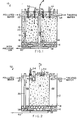
- Fig. 1 shows an aerobic ecological fluidized bed system 10 of the invention which comprises a container 12 with a layer of coarse medium 14 on the bottom of the container 12 such as a particulate porous rock-type material like pumice rock and the container 12 having therein a particulate, semi-buoyant fine medium material 16 such as finely divided 6.4 to 38.1 mm (1/2 to 1-1/2 inch) pumice rock above the coarse media and dispersed in the water.
- the container includes a porous mesh barrier 18, typically of plastic, which separates the coarse media layer 14 from the fine media material 16.
- the container includes a generally upright water inlet pipe 20 having an inlet 22 for the introduction of polluted water into the inlet pipe, the inlet pipe extending into the coarse media layer 14 at the bottom of the container 10.
- the water 24 forms a top layer in the container 10.
- the container 10 includes pipe 26 which also contains the aerator for the airlift pump 32 which recirculates the water within the system of container 10.
- the airlift pipe 26 has a flow path 28 in the coarse media layer 14 and its upper part close to the surface of the water 24.
- the airlift aerators 32 are connected to a supply of air 36.
- the airlift pump means used comprises tube 26 and the aerator 32.
- the airlift pump works by creating a lighter water column in the pipe 26 of Fig. 1. This is achieved by blowing air through pipe 36 to an aerator 32.
- the fine bubbles in the water column in pipe 26 reduce the specific gravity of this water in relation to the rest of the water in the EFB.
- the system 10 includes aquatic-type plants 34 having roots disposed in the fine media 16 and then upwardly form the surface of the water 24 as part of the ecosystem used to treat the polluted water.
- the container 12 also contains aeration devices 38 in the coarse media layer and a high pressure air and/or water supply in line 40 so that high pressure air may be periodically introduced into the aerator 38 to dislodge waste material from the coarse and porous layer 14 and to discharge the solid waste material from the discharge line 54.
- the coarse media layer 14 can be comprised of coarse rock or plastic media which minimizes the disruption to hydraulic flow, while the fine media 16 employed in the container 12 should have a high surface to volume ratio; that is, have a non-smooth surface or typically a rough surface and can be composed of plastic or natural materials with a specific gravity close to one, allowing movement of the fine media 16 with the hydraulic flow of the water to form an ecological fluidized bed.
- the rapid recirculation rate within the container 12 can be achieved by a single airlift pump 32 or multiple pumps may be employed within the same body of the media.
- the air may be supplied, for example, through line 36 by an air blower matched to the design of the airlift pump such as to allow maximum recirculation rate for a minimum flow of air.
- the ecological fluidized bed is bioaugmented with a variety of bacteria, fungi, protozoas, nematodes and the like and animals to provide a complete ecosystem for the treatment of the polluted water introduced into the inlet 22 and to provide treated water removed from the outlet 54 from the top water layer 24.
- the higher plants 34 can be grown on the top surface with their roots extending into the fine media 16. The roots of the higher aquatic plants 34 provide sites for bacteria and the plants can take up nutrients and metals from the polluted water.
- Fig. 2 is directed to an anaerobic ecological fluidized bed system 52 of the invention, comprising a high rate bioreactor which biologically denitrifies polluted water.
- the anaerobic system 52 includes a cylinder 42 placed on top of the coarse layer 14 and includes a perforated sump area 44 in the upper portion of the fine media 16, and which perforated sump area includes a mechanical pump 46 having an outlet which is discharged into the water column 48 formed between the interior surface of the container 12 and the outer surface of the cylinder 42 and with the system containing a fine media and water, 25.4 to about 76.2 mm (one to about 3 inches) above the water level of the water in the outside water column 48.
- Fig. 1 As in Fig.
- the ecological fluidized bed system 52 can be bioaugmented with suitable minerals, bacteria, organic compounds and other biologicals to assist in the performance as a denitrifier, and plants 34 may be grown optionally on the surface of the fine media 16.
- the system 52 has limited exposure to the oxygen in the atmosphere and as desired the container 12 may be closed by a cover to reduced contact with the atmosphere and to provide for the discharge of nitrogen.
- the mechanical pump 46 and the sump 44 pumps polluted water draining into the sump 44 from the fine media fluidized bed 16 into the water column 48 outside of the cylinder 42, which causes the polluted water introduced into inlet 22 to pass down under the bottom rim of the cylinder 42 and to flow out through the coarse media layer 14 and into the fine media ecological fluidized bed 16, then the water as treated in the ecological fluidized bed is then rapidly recycled into the perforated sump 44 to the mechanical pump 46 for recirculation at a high rate. Because polluted water passed up through the fine media 16, nitrogen and other gases given off in the treatment are carried to the surface 50 of the fluidized bed. In the anaerobic system 52 as described the process of denitrification is anaerobic, which allows the recirculating water within the ecological fluidized bed system 52 to operate without adding oxygen to the water.
- Figs. 3,4, and 5 are directed to a lagoon-type system employing a plurality of ecological fluidized beds, for example, as shown in Fig. 1.
- the ecological fluidized bed (EFB) system 10 of Fig. 1 can be employed as a single unit, preferably a number of EFBs can be connected together.
- the size and number of the EFBs in the system will depend on the strength of the pollutants and the degree of treated water desired.
- the flow rate of recirculation of the polluted water within one or more of the EFB systems can be adjusted depending on the hydraulic flow through the total system and the level of pollutants in the polluted water.
- the connections can be done by normal pipe work and plumbing to connect the inlets and outlets.
- FIG. 3 being a top plan view showing a lagoon configuration with a plurality of EFBs joined with an airlift pump 32 for each EFB system, with the EFB systems both employed in series or parallel, showing a lagoon 62, with a barrier 64 across the lagoon to separate the EFB systems.
- Sectional views of the lagoon system 60 as shown along lines 4-4 and 5-5 of Fig. 3, illustrate, for example, the openings 66 between each of the connected EFB systems.
- FIG. 3 in particular shows a collection distribution header 70 for the collection of polluted water and directing the polluted water into the inlet of the plurality of EFB systems and a distribution header 68 for the collection and distribution of the polluted water which has been treated and the discharge of treated water form the lagoon system 60.
- the lagoon system 60 there are optionally barriers 64 across the lagoon and these barriers allow for the pump flow of the polluted water as it passes through the barrier opening 66 between the EFB systems.
- the opening 66 may be a through passage without restriction or can be a valve which can be adjusted to provide for adjusted hydraulic flow to the polluted water between the various EFB systems.
- the ecology employed within the multiple EFB systems is similar to the single treatment described or may vary as desired.
- the lagoon system 60 as described and illustrated allows for an inexpensive way of utilizing a large number of the EFB systems in series and parallel to treat polluted or waste water in a lagoon.
- Figs. 1 through 5 are to illustrate the water flow of the polluted water within the lagoon system 60.
- FIG 6 illustrates a floating EFB system 72 similar to the EFB system of Fig. 1, wherein the container comprises a flexible bag 12 and the system includes a flotation collar 76 on the upper level thereof, which floats the EFB system in a polluted body of water 74.
- a flotation collar supports in particular an EFB system in a body of water, whether as an aerobic or anaerobic system (see Figs. 1 and 2).
- a body of water 74 can act simply as a support medium for the particular one or more EFB systems in the body of water, which results in an inexpensive method of containment as there is a minimal need for a physical structure, since a flexible bag 12 with a flotation collar 76 is all that is required to support the-EFB treatment system within the body of water.
- the influent pipe work can be connected to a polluted body of water or to one or more EFB systems in a series or parallel. If desired, the floating EFB systems can then be connected in a floating arrangement by attached ropes.
- Fig. 6 in operation, water is directed into the inlet 22.
- the airlift pump aerator 32 takes air from air source 36 as in the operation of Fig. 1, the treated water is recirculated and can then be discharged through discharge 54 either to another EFB system not shown or to the body of water 74.
- the EFB systems are particularly useful for treating polluted water which may give off dangerous gases in treatment.
- the entire EFB system is then housed in a sealed container, which may be of a rigid or flexible material and the toxic gases can then be exhausted through pipes or through biological or activated carbon filters or the equivalent therein (not shown) to limit air pollution.
- the EFB systems employed in a series or parallel might be employed around a floating barge which has a source of power and these clusters of EFB systems then can be anchored in rivers, canals, lakes and ponds, and in ocean or marine configurations for treating high volumes of polluted water with minimal energy.
- the power supply typically may be from wind generators and solar panels which charge battery banks to power electric blowers for the airlift pumps or may be conventional power supplies, and may be used to power the mechanical pumps for anaerobic configuration EFB systems. Or alternatively, wind power can be used to charge a pneumatic cylinder which stores compressed air for use in the airlift pump.
- the floating EFB systems can also be contained in extra-long, flexible containers, which with suitable flotation columns can treat extremely large volumes of water using media with specific gravity of close to 1 and flexible pipe work as described and illustrated in connection with Figs. 1 and 2.
- the flexible wall containers can also be housed in a ditch or trough.
- the ecological fluidized bed systems provide for the rapid, efficient treatment of polluted water to a treated water state through the employment of a dispersion of fine media particles, typically semi-buoyant and in the presence of an ecosystem to treat the polluted water and then rapidly recycling and recirculating the fine media with the water in the ecosystem in a fluidized bed arrangement to provide very efficient exposure to the large surface area of the fine media with flow rates up to about 100 times the flow-through of the water in the bed system.
Landscapes
- Life Sciences & Earth Sciences (AREA)
- Engineering & Computer Science (AREA)
- Microbiology (AREA)
- Water Supply & Treatment (AREA)
- Hydrology & Water Resources (AREA)
- Environmental & Geological Engineering (AREA)
- Biodiversity & Conservation Biology (AREA)
- Chemical & Material Sciences (AREA)
- Organic Chemistry (AREA)
- Biotechnology (AREA)
- Botany (AREA)
- Biological Treatment Of Waste Water (AREA)
- Purification Treatments By Anaerobic Or Anaerobic And Aerobic Bacteria Or Animals (AREA)
- Separation Of Suspended Particles By Flocculating Agents (AREA)
- Water Treatment By Sorption (AREA)
Abstract
Description
Claims (14)
- A method for the treatment of polluted water in a fluidized bed system to provide treated water, which method comprises:(a) providing a housing (12) having first and second adjacent chambers therein, said first and second chambers connected to permit the flow of circulated polluted water between said first and second chambers in said housing (12);(b) introducing polluted water to be treated at a flow-through rate into said first chamber;(c) maintaining in said second chamber circulating polluted water with semi-buoyant particulate media (16) in the presence of an ecosystem means for the treatment of the polluted water, wherein the semi-buoyant particulate media (16) has a specific gravity of 0.9 to 1.0 and ranges in volume from 10 to 60 percent of the volume of said polluted water of said second chamber, said ecosystem means consisting of a complete and balanced ecosystem;(d) maintaining in said first chamber circulating polluted water essentially free of particulate media, said particulate media being substantially confined to said second chamber;(e) circulating the polluted water between the first and second chambers at a rate of 10 to 1000 times the flow-through rate of the polluted water;(f) providing plants and/or filter feeders, at least in said second chamber, to augment the biological interaction;(g) maintaining exposed to air the surface of the water in said second chamber; and(h) withdrawing from the housing a treated water essentially free of particulate media.
- The method of claim 1, wherein said first chamber further comprises an airlift pipe (26) with an aerator means (32) and which method includes introducing air into the aerator means (32) to draw polluted water into the bottom end of the airlift pipe (26) and to provide an upwardly moving column of polluted water in the airlift pipe (26) and discharging the aerated, polluted water from a top end of the airlift pipe (26).
- The method of claim 1, which method includes pumping the polluted water from an upper sump portion of the second chamber into the first chamber.
- The method of any one of the preceding claims, which includes prefiltering the introduced polluted water through a layer of coarse filter media (14) at the bottom of the housing (12).
- The method of any one of the preceding claims, which includes periodically introducing high pressure air or water into the layer of the coarse filter media (14) to dislodge waste material.
- The method of any one of the preceding claims, which includes impregnating said ecosystem means into said particulate media (16) prior to adding said media into said housing (12).
- The method of any one of the preceding claims, which includes providing a plurality of housings and introducing the treated water from one housing into one or more subsequent housings until treated water of desired purity is obtained.
- An ecological fluidized bed system for the treatment of polluted water to provide treated water, which system comprises:(a) a housing (12) having separate adjacent first and second chambers, said first and second chambers connected to permit the flow of circulated polluted water in the housing between said first and second chambers;(b) an inlet in said first chamber to introduce into said first chamber polluted water to be treated at an inlet flow-through rate, said first chamber having circulated, polluted water to be treated and essentially free of particulate media;(c) an inlet in said second chamber to introduce polluted water to be treated into said second chamber, and an outlet in said first chamber to discharge polluted water into said second chamber;(d) said second chamber comprised of polluted water, semi-buoyant particulate media (16) and an ecosystem means to treat the polluted water, the particulate media (16) in said second chamber having a specific gravity of 0.9 to 1.0 and ranging in volume from 10 to 60 percent of the volume of the polluted water of said second chamber, said ecosystem means consisting of a complete and balanced ecosystem;(e) an outlet (54) to withdraw treated water from the housing (12) essentially free of particulate media;(f) circulating means (32,46) to circulate polluted water between said first and second chambers at a circulation flow rate of at 10 to 1000 times the inlet flow-through rate of the polluted water into said first chamber;(g) means to introduce polluted water at an inlet flow-through rate into the inlet of said first chamber; and(h) plants and/or filter feeders, at least in said second chamber, to augment the biological interaction, wherein the surface of water in said second chamber is exposed to air.
- The system of claim 8, wherein said first chamber further comprises a generally vertical airlift pipe (26) having a first bottom inlet and second top outlet end (30) in the housing (12) and the circulating means comprises an aerator means (32) in the airlift pipe (26) to provide an upward flow of aerated polluted water within the airlift pipe (26) to draw in polluted water at the first bottom inlet end and to discharge aerated polluted water at the second top outlet end (30) into said second chamber.
- The system of claim 8 or claim 9, which includes a layer of coarse filter media (14) at the bottom of the housing (12) to filter the polluted water introduced into the inlet of said first chamber.
- The system of claim 10, which includes means (38,40) to introduce high pressure air or water into the layer of coarse filter media (14) to dislodge waste material from the layer.
- The system of claim 8 or claim 9, wherein the circulating means comprises a mechanical pump (46) in a sump (44) within said second chamber to pump polluted water from said second chamber essentially free of particulate media into said first chamber.
- The system of any one of claims 8 to 12, wherein said plants (34) in said second chamber are in the upper portion of said second chamber and have their plant roots in the polluted water, particulate media (16) and ecosystem means.
- The system of any one of claims 8 to 13, which includes a plurality of interconnected housings for the sequential treatment of polluted water.
Applications Claiming Priority (3)
| Application Number | Priority Date | Filing Date | Title |
|---|---|---|---|
| US149964 | 1993-11-10 | ||
| US08/149,964 US5486291A (en) | 1993-11-10 | 1993-11-10 | Ecological fluidized bed method for the treatment of polluted water |
| PCT/US1994/012901 WO1995013246A1 (en) | 1993-11-10 | 1994-11-09 | System and method for treatment of polluted water |
Publications (3)
| Publication Number | Publication Date |
|---|---|
| EP0728122A1 EP0728122A1 (en) | 1996-08-28 |
| EP0728122A4 EP0728122A4 (en) | 1998-07-29 |
| EP0728122B1 true EP0728122B1 (en) | 2003-09-17 |
Family
ID=22532548
Family Applications (1)
| Application Number | Title | Priority Date | Filing Date |
|---|---|---|---|
| EP95901186A Expired - Lifetime EP0728122B1 (en) | 1993-11-10 | 1994-11-09 | System and method for treatment of polluted water |
Country Status (7)
| Country | Link |
|---|---|
| US (2) | US5486291A (en) |
| EP (1) | EP0728122B1 (en) |
| AT (1) | ATE250011T1 (en) |
| AU (1) | AU679810B2 (en) |
| CA (1) | CA2176260A1 (en) |
| DE (1) | DE69433164D1 (en) |
| WO (1) | WO1995013246A1 (en) |
Families Citing this family (90)
| Publication number | Priority date | Publication date | Assignee | Title |
|---|---|---|---|---|
| JP3056361B2 (en) * | 1993-11-08 | 2000-06-26 | シャープ株式会社 | Wastewater treatment device and wastewater treatment method |
| JP2975276B2 (en) * | 1994-11-16 | 1999-11-10 | ベスト工業株式会社 | Cleaning method for floating filter media for biological filtration equipment |
| JP3111846B2 (en) * | 1994-12-13 | 2000-11-27 | 株式会社日立製作所 | Purification device |
| CA2139247C (en) * | 1994-12-29 | 1999-01-19 | Stephen G. Simmering | Sewage treatment system using peat and a constructed wetland |
| EP0739859B1 (en) * | 1995-04-18 | 2000-07-12 | Sharp Kabushiki Kaisha | Apparatus and method for waste water treatment using charcoal biologically activated |
| US5993649A (en) * | 1996-01-03 | 1999-11-30 | Debusk; Thomas A. | Sequential biological-chemical water treatment system |
| US5733453A (en) * | 1996-07-15 | 1998-03-31 | Azurea, Inc. | Wastewater treatment system and method |
| US5951866A (en) * | 1996-07-31 | 1999-09-14 | Grove; John E. | Cold climate wetland waste water treatment system |
| US5893975A (en) * | 1997-04-23 | 1999-04-13 | Roux Associates, Inc. | Enhanced subsurface flow constructed wetland |
| AU7482798A (en) * | 1997-05-13 | 1998-12-08 | Advanced Biological Services, Inc. | Reaction sites for microorganisms used to biodegrade contaminants and methods ofuse |
| US6159371A (en) * | 1997-05-30 | 2000-12-12 | Albuquerque Public Schools District No. 12 | Constructed wetlands remediation system |
| US6110389A (en) * | 1997-10-10 | 2000-08-29 | Horowitz; Amikam | Filtration unit |
| US6287469B1 (en) * | 1997-10-17 | 2001-09-11 | Ashco-A-Corporation | Home wastewater treatment plant |
| US6205708B1 (en) | 1997-11-17 | 2001-03-27 | Edward G. Gatliff | Treatment material pumping system |
| US6189262B1 (en) * | 1997-11-26 | 2001-02-20 | Edward G. Gatliff | Method of treating industrial waste water |
| AU1549600A (en) * | 1998-12-04 | 2000-06-26 | Knud Peter Brockdorff | A method and a bio reactor for use in the purification of water, and a bio-element for use in this connection |
| US6277274B1 (en) | 1999-04-16 | 2001-08-21 | Larry Steven Coffman | Method and apparatus for treating stormwater runoff |
| US6086755A (en) * | 1999-05-21 | 2000-07-11 | Tepper; Julius | Floating hydroponic biofiltration device |
| GB2358858A (en) * | 1999-08-28 | 2001-08-08 | Oceans Environmental Engineeri | Portable wastewater treatment apparatus |
| US6447681B1 (en) * | 2000-08-07 | 2002-09-10 | Kent Sea Tech Corporation | Aquaculture wastewater treatment system and method of making same |
| AUPR012400A0 (en) * | 2000-09-13 | 2000-10-05 | Rootzone Australia Pty Ltd | Polluted water treatment system |
| ITMI20010024A1 (en) * | 2001-01-10 | 2002-07-10 | Consiglio Naz Della Ricerche | PROCEDURE AND PLANT FOR BIODEPURATION OF UNDERWATER OF WASTEWATER DISCHARGED INTO THE SEA |
| GB0124433D0 (en) * | 2001-10-11 | 2001-12-05 | Univ Manchester Metropolitan | Improvemnts in or relating to fluid bed expansion and fluidisation |
| WO2003042114A1 (en) * | 2001-11-14 | 2003-05-22 | Dharma Living Systems, Inc. | Integrated hydroponic and fixed-film wastewater treatment systems and associated methods |
| US6830688B2 (en) * | 2001-11-14 | 2004-12-14 | Dharma Living Systems, Inc. | Integrated hydroponic and wetland wastewater treatment systems and associated methods |
| US6863816B2 (en) * | 2002-06-17 | 2005-03-08 | Dharma Living Systems, Inc. | Tidal vertical flow wastewater treatment system and method |
| US6881338B2 (en) * | 2002-06-17 | 2005-04-19 | Dharma Living Systems, Inc. | Integrated tidal wastewater treatment system and method |
| CA2510570A1 (en) | 2002-12-17 | 2004-07-22 | Boston Scientific Limited | Spacer for sling delivery system |
| US7029586B2 (en) * | 2003-02-28 | 2006-04-18 | Dharma Living Systems, Inc. | Integrated tidal wastewater treatment system and method |
| US6896805B2 (en) * | 2003-10-20 | 2005-05-24 | Dharma Living Systems, Inc. | Tidal vertical flow wastewater treatment system and method |
| US20050173338A1 (en) * | 2004-02-11 | 2005-08-11 | Bretsch Mary K. | Method of treating water for fine suspended solids using confined exposure to a living colony of hydrocotyle ranunculoides |
| US7347940B2 (en) * | 2004-06-17 | 2008-03-25 | Worrell Water Technologies, Llc | Nitrogen removal system and method for wastewater treatment lagoons |
| US7101476B2 (en) * | 2004-07-15 | 2006-09-05 | Jung Yong Kim | Soil covered environmentally affirmative household sewage treatment system |
| AU2005306597B2 (en) * | 2004-11-22 | 2009-10-08 | Nubian Water Systems Pty Limited | Waste water treatment process system |
| EP1838629A4 (en) * | 2004-11-22 | 2010-11-24 | Water Systems Pty Limited Nubian | Waste water treatment process system |
| US7316776B2 (en) * | 2005-01-24 | 2008-01-08 | Eric Kieselbach | Aquarium filtration system with bio-reactor |
| US20060180546A1 (en) * | 2005-02-15 | 2006-08-17 | William L. Stuth, Sr. | Wastewater treatment system and method |
| FR2889457B1 (en) * | 2005-08-02 | 2008-04-11 | Sarl Aquatique De La Moine Sar | INSTALLATION FOR THE AUTONOMOUS SANITATION OF DOMESTIC EFFLUENTS |
| US7587858B2 (en) * | 2005-08-11 | 2009-09-15 | Roy E. Hock | Method and apparatus for cultivation of subaquatic vegetation |
| CA2784249C (en) | 2006-02-09 | 2015-08-11 | Alcoa Inc. | Methods, apparatus and systems for polishing wastewater utilizing, natural media filtration |
| WO2008014087A2 (en) * | 2006-07-25 | 2008-01-31 | Fountainhead, Llc | Buoyant plant habitat and process for its manufacture |
| CN101652166B (en) * | 2006-11-06 | 2013-05-15 | Wet-Tek有限公司 | Portable water treatment device |
| US7575683B2 (en) * | 2007-01-26 | 2009-08-18 | Kauppi Frederick J | Portable wetlands |
| US20100276360A1 (en) * | 2007-02-08 | 2010-11-04 | Alcoa Inc. | Methods, apparatus and systems for polishing wastewater utilizing natural media filtration |
| US7749384B2 (en) * | 2007-05-23 | 2010-07-06 | Patton David W | De-nitrification treatment system and method |
| NL1034285C2 (en) | 2007-08-24 | 2009-02-25 | Bright Water Company B V | Floating switchable biological swamp plant filter. |
| AT506483B1 (en) * | 2008-02-22 | 2009-11-15 | Minnova Mineralien Handelsgese | WATER INTRODUCTION ARRANGEMENT |
| EP2274245B1 (en) * | 2008-04-17 | 2015-03-25 | Alnarp Cleanwater Technology AB | A phytosystem, its use and method for treatment of sewage |
| WO2009134546A1 (en) * | 2008-04-30 | 2009-11-05 | Fountainhead, Llc | Adjustably rigid floating island system |
| US7666302B2 (en) * | 2008-07-07 | 2010-02-23 | David W Jenkins | Dual cell nitrogen removal apparatus |
| KR101046277B1 (en) * | 2008-07-16 | 2011-07-04 | 주식회사 부강테크 | Wastewater Treatment System for Two-stage Multi-layer Biofiltration Process |
| CN101575155B (en) * | 2008-12-09 | 2011-07-27 | 李盈庭 | Efficient and energy-saving sewage treatment method and device |
| CN102317215A (en) * | 2008-12-22 | 2012-01-11 | 犹他州立大学研究基金会 | Subsea system and method for removing unwanted substances from an aqueous medium |
| AP2011005805A0 (en) | 2009-01-13 | 2011-08-31 | Access Business Group Int Llc | Gravity feed water treatment system. |
| US8287728B2 (en) * | 2009-02-10 | 2012-10-16 | Fountainhead L.L.C. | Elevated swale for treatment of contaminated stormwater |
| AT508098B1 (en) * | 2009-03-20 | 2015-06-15 | Hackner Heinz | DEVICE FOR CLEANING WATER FROM SWIMMING POOLS OR POOLS |
| US8585892B2 (en) * | 2010-01-13 | 2013-11-19 | Biofilter Systems, Llc | System and process for removing nitrogen compounds and odors from wastewater and wastewater treatment system |
| US9272931B2 (en) | 2010-01-13 | 2016-03-01 | Biofilter Systems, Llc | System and process for removing nitrogen compounds and odors from wastewater and wastewater treatment system |
| US8388833B2 (en) | 2010-09-23 | 2013-03-05 | Biofilter Systems, Llc | System and process for removing nitrogen compounds and odors from wastewater and wastewater treatment system |
| WO2011088105A1 (en) * | 2010-01-13 | 2011-07-21 | Biofilter Systems, Llc | System and process for removing nitrogen compounds and odors from wastewater and wastewater treatment system |
| US20110233141A1 (en) * | 2010-03-24 | 2011-09-29 | Mclain John | Wastewater treatment system and methods for constructing the same |
| US8382982B2 (en) | 2010-06-04 | 2013-02-26 | John L. Hondulas | Apparatus merging wetland plants with a floating substrate to treat pollution in any river, lake or body of water |
| AU2011267932B2 (en) | 2010-06-14 | 2015-09-17 | Arconic Inc. | Wastewater treatment system and method for removal of contaminants via mixed metal oxide beds |
| KR101220314B1 (en) * | 2010-12-24 | 2013-01-09 | 한국지질자원연구원 | Oxidation pond for treating acid mine drainage |
| DE102011100143B4 (en) * | 2011-04-29 | 2022-12-15 | Deutsches Zentrum für Luft- und Raumfahrt e.V. | System for metabolizing organic matter and method for metabolizing organic matter |
| ES2370878B1 (en) * | 2011-07-05 | 2013-02-11 | Gestión Depuración Y Servicios Sl | PROCEDURE FOR THE CLEANING OF WASTEWATER THROUGH ECOLOGICAL EQUIPMENT AND COMPACTS. |
| US8303816B2 (en) | 2011-08-22 | 2012-11-06 | Modular Wetland Systems, Inc. | Wetland biofilter chamber with peripheral catch basin and method of use thereof |
| US8940170B2 (en) | 2011-08-22 | 2015-01-27 | Modular Wetland Systems, Inc. | Triple-chambered wetland biofilter treatment system |
| US11926548B2 (en) | 2019-11-24 | 2024-03-12 | Bio Clean Environmental Services, Inc. | Flow control riser within a stormwater treatment system |
| CN102515356A (en) * | 2011-11-28 | 2012-06-27 | 杜建强 | Saturated filter bed for treating polluted water body |
| US20130276370A1 (en) * | 2012-04-19 | 2013-10-24 | Louis A. Licht | Phytoremediation test cell and method |
| US9085474B2 (en) | 2012-12-28 | 2015-07-21 | Lean Environment Inc. | Modular system for storm water and/or waste water treatment |
| CN105008289B (en) | 2013-01-11 | 2017-06-06 | 奥科宁克有限公司 | Waste Water Treatment and method |
| DE202015009083U1 (en) * | 2015-01-19 | 2016-09-06 | Minnova Bns Gmbh | Device for binding dissolved phosphorus in ponds, swimming pools, biopools and aquariums |
| US20160279542A1 (en) * | 2015-03-26 | 2016-09-29 | Thomas G. Stroope | Pond Filter |
| CN105712484B (en) * | 2016-04-28 | 2018-12-28 | 河海大学 | A kind of CW-MFC coupled system and its biodegrading process for Degradation of Azo Dyes |
| US10342189B2 (en) * | 2016-05-17 | 2019-07-09 | Bubbleclear | Aerobic, bioremediation treatment system comprising floating inert media in an aqueous environment |
| CN106904729A (en) * | 2017-03-29 | 2017-06-30 | 天津西敦津洋环保科技有限公司 | A kind of hybrid particles system and method for sewage disposal |
| CN106904741A (en) * | 2017-03-29 | 2017-06-30 | 天津西敦津洋环保科技有限公司 | A kind of sewage disposal device of light particle system |
| CN106904751A (en) * | 2017-03-29 | 2017-06-30 | 中国科学院广州能源研究所 | A kind of micro- heavy particle system and method for sewage disposal |
| CN106890604B (en) * | 2017-03-29 | 2023-09-05 | 天津西敦津洋环保科技有限公司 | Mixed particle suspension system |
| CN106890603B (en) * | 2017-03-29 | 2024-08-06 | 天津西敦津洋环保科技有限公司 | Light particle suspension system |
| US12121890B2 (en) * | 2017-03-29 | 2024-10-22 | Wesdon-Tienda Environmental Sciences Co. Ltd. | Light particle or mixed particle system for wastewater treatment |
| US20180280835A1 (en) * | 2017-03-29 | 2018-10-04 | Wesdon-Tienda Environmental Sciences Co. Ltd. | Container-type apparatus with a suspended particle system for wastewater treatment |
| CN108358320B (en) * | 2018-05-18 | 2023-09-26 | 江西省科学院能源研究所 | Siphon type composite vertical subsurface flow constructed wetland |
| US11148965B2 (en) * | 2018-07-16 | 2021-10-19 | Yonathan RECHES | Process for the biological purification of nutrient-contaminated wastewater |
| CN108892249A (en) * | 2018-08-30 | 2018-11-27 | 上海水平衡环境科技发展股份有限公司 | A kind of air-flotation type floating stuffing original position purifier and process for purifying water |
| MA44332B1 (en) * | 2018-12-25 | 2020-10-28 | Univ Sultan Moulay Slimane Usms | New design of an external loop bioreactor for the treatment of liquid effluents |
| CN110272127A (en) * | 2019-07-05 | 2019-09-24 | 佛山光性科技有限公司 | A kind of microflora of fish jar purification of water quality |
| EP4274506A4 (en) * | 2021-01-11 | 2025-02-26 | Digital Surgery Systems, Inc. | RECORDING DEGRADATION FIX FOR SURGICAL NAVIGATION INTERVENTIONS |
Family Cites Families (7)
| Publication number | Priority date | Publication date | Assignee | Title |
|---|---|---|---|---|
| US3563888A (en) * | 1968-08-21 | 1971-02-16 | Research Corp | Method and apparatus for treating waste-containing liquor |
| JPS57198787A (en) * | 1981-05-29 | 1982-12-06 | Kureha Chem Ind Co Ltd | Preparation of raw material for preparing carbon material |
| US4415450A (en) * | 1981-12-28 | 1983-11-15 | The United States Of America As Represented By The Administrator Of The National Aeronautics And Space Administration | Method for treating wastewater using microorganisms and vascular aquatic plants |
| FR2533548B1 (en) * | 1982-09-28 | 1985-07-26 | Degremont | METHOD AND APPARATUS FOR ANAEROBIC TREATMENT OF WASTE WATER IN A GRANULAR MATERIAL FILLED FILTER |
| JPS59230694A (en) * | 1983-06-14 | 1984-12-25 | Ube Ind Ltd | Fluidized aeration bed using granular media |
| US5087353A (en) * | 1988-11-03 | 1992-02-11 | Ecological Engineering Associates | Solar aquatic apparatus for treating waste |
| US5228998A (en) * | 1992-05-26 | 1993-07-20 | Diclemente Lee M | Floating biological contactor |
-
1993
- 1993-11-10 US US08/149,964 patent/US5486291A/en not_active Expired - Fee Related
-
1994
- 1994-11-09 AT AT95901186T patent/ATE250011T1/en not_active IP Right Cessation
- 1994-11-09 WO PCT/US1994/012901 patent/WO1995013246A1/en not_active Ceased
- 1994-11-09 AU AU10523/95A patent/AU679810B2/en not_active Ceased
- 1994-11-09 DE DE69433164T patent/DE69433164D1/en not_active Expired - Lifetime
- 1994-11-09 CA CA 2176260 patent/CA2176260A1/en not_active Abandoned
- 1994-11-09 EP EP95901186A patent/EP0728122B1/en not_active Expired - Lifetime
-
1995
- 1995-06-01 US US08/457,990 patent/US5618413A/en not_active Expired - Fee Related
Also Published As
| Publication number | Publication date |
|---|---|
| AU1052395A (en) | 1995-05-29 |
| US5486291A (en) | 1996-01-23 |
| AU679810B2 (en) | 1997-07-10 |
| WO1995013246A1 (en) | 1995-05-18 |
| DE69433164D1 (en) | 2003-10-23 |
| CA2176260A1 (en) | 1995-05-18 |
| EP0728122A1 (en) | 1996-08-28 |
| US5618413A (en) | 1997-04-08 |
| EP0728122A4 (en) | 1998-07-29 |
| ATE250011T1 (en) | 2003-10-15 |
Similar Documents
| Publication | Publication Date | Title |
|---|---|---|
| US5486291A (en) | Ecological fluidized bed method for the treatment of polluted water | |
| ES2315009T3 (en) | REACTOR SYSTEMS WITH SEQUENTIAL LOADS OF ANOXY BALANCE MIXTURE. | |
| US4997568A (en) | Process and apparatus for a biological reactor to purify water | |
| AU2002301606B2 (en) | Batch Style Wastewater Treatment Apparatus Using Biological Filtering Process and Wastewater Treatment Method Using The Same | |
| US9133044B2 (en) | Method and device for the treatment of waste water | |
| US6413427B2 (en) | Nitrogen reduction wastewater treatment system | |
| US5534141A (en) | Wastewater treatment system with in-pond clarifier | |
| US5421999A (en) | Floating nitrification reactor in a treatment pond | |
| CN207699412U (en) | A kind of Drain contamination for river channel mouth sewage-treatment plant | |
| CN104724817B (en) | Net cage type biological carrier, immobilized microbiological treatment sewage device and application of immobilized microbiological treatment sewage device | |
| KR101996238B1 (en) | Module type sea water recirculating filteration system and operating method | |
| US3733263A (en) | Waste treatment system | |
| KR20130019164A (en) | Continuous time water purification apparatus using adsorption pack | |
| JP3469797B2 (en) | Sewage treatment method and apparatus | |
| CN212292986U (en) | Mud film biochemical sewage treatment system | |
| KR100414688B1 (en) | Foul drain processing unit and method using settling chamber and biofilm filteration aquarium | |
| KR100873052B1 (en) | Open Wastewater and Sewage Treatment Equipment | |
| KR100458764B1 (en) | Method and apparatus for the treatment of contaminated water by submersible biological aerated filter | |
| RU2136614C1 (en) | Device for biological elimination of organic substances, nitrogen and phosphorus compounds from sewage waters | |
| KR101898183B1 (en) | Wastewater treatment apparatus equipped with a complex carrier and a spray water flow apparatus, and a method for removing phosphorus and nitrogen using the same | |
| CN109836016B (en) | River drain sewage treatment plant | |
| JP2000354858A (en) | Sewage treatment method and device therefor | |
| KR101181800B1 (en) | The method and apparatus to treat municipal and industrial wastewater | |
| JP2002273471A (en) | Equipment and method for purifying water | |
| KR102497135B1 (en) | Advanced wastewater complex treatment apparatus with three step filtering type |
Legal Events
| Date | Code | Title | Description |
|---|---|---|---|
| PUAI | Public reference made under article 153(3) epc to a published international application that has entered the european phase |
Free format text: ORIGINAL CODE: 0009012 |
|
| 17P | Request for examination filed |
Effective date: 19960607 |
|
| AK | Designated contracting states |
Kind code of ref document: A1 Designated state(s): AT BE CH DE DK ES FR GB GR IE IT LI LU MC NL PT SE |
|
| A4 | Supplementary search report drawn up and despatched |
Effective date: 19980615 |
|
| AK | Designated contracting states |
Kind code of ref document: A4 Designated state(s): AT BE CH DE DK ES FR GB GR IE IT LI LU MC NL PT SE |
|
| 17Q | First examination report despatched |
Effective date: 19991221 |
|
| GRAH | Despatch of communication of intention to grant a patent |
Free format text: ORIGINAL CODE: EPIDOS IGRA |
|
| GRAS | Grant fee paid |
Free format text: ORIGINAL CODE: EPIDOSNIGR3 |
|
| GRAA | (expected) grant |
Free format text: ORIGINAL CODE: 0009210 |
|
| AK | Designated contracting states |
Kind code of ref document: B1 Designated state(s): AT BE CH DE DK ES FR GB GR IE IT LI LU MC NL PT SE |
|
| PG25 | Lapsed in a contracting state [announced via postgrant information from national office to epo] |
Ref country code: NL Free format text: LAPSE BECAUSE OF FAILURE TO SUBMIT A TRANSLATION OF THE DESCRIPTION OR TO PAY THE FEE WITHIN THE PRESCRIBED TIME-LIMIT Effective date: 20030917 Ref country code: LI Free format text: LAPSE BECAUSE OF FAILURE TO SUBMIT A TRANSLATION OF THE DESCRIPTION OR TO PAY THE FEE WITHIN THE PRESCRIBED TIME-LIMIT Effective date: 20030917 Ref country code: IT Free format text: LAPSE BECAUSE OF FAILURE TO SUBMIT A TRANSLATION OF THE DESCRIPTION OR TO PAY THE FEE WITHIN THE PRESCRIBED TIME-LIMIT;WARNING: LAPSES OF ITALIAN PATENTS WITH EFFECTIVE DATE BEFORE 2007 MAY HAVE OCCURRED AT ANY TIME BEFORE 2007. THE CORRECT EFFECTIVE DATE MAY BE DIFFERENT FROM THE ONE RECORDED. Effective date: 20030917 Ref country code: FR Free format text: LAPSE BECAUSE OF FAILURE TO SUBMIT A TRANSLATION OF THE DESCRIPTION OR TO PAY THE FEE WITHIN THE PRESCRIBED TIME-LIMIT Effective date: 20030917 Ref country code: CH Free format text: LAPSE BECAUSE OF FAILURE TO SUBMIT A TRANSLATION OF THE DESCRIPTION OR TO PAY THE FEE WITHIN THE PRESCRIBED TIME-LIMIT Effective date: 20030917 Ref country code: BE Free format text: LAPSE BECAUSE OF FAILURE TO SUBMIT A TRANSLATION OF THE DESCRIPTION OR TO PAY THE FEE WITHIN THE PRESCRIBED TIME-LIMIT Effective date: 20030917 Ref country code: AT Free format text: LAPSE BECAUSE OF FAILURE TO SUBMIT A TRANSLATION OF THE DESCRIPTION OR TO PAY THE FEE WITHIN THE PRESCRIBED TIME-LIMIT Effective date: 20030917 |
|
| REG | Reference to a national code |
Ref country code: GB Ref legal event code: FG4D |
|
| REG | Reference to a national code |
Ref country code: CH Ref legal event code: EP |
|
| REF | Corresponds to: |
Ref document number: 69433164 Country of ref document: DE Date of ref document: 20031023 Kind code of ref document: P |
|
| REG | Reference to a national code |
Ref country code: IE Ref legal event code: FG4D |
|
| PG25 | Lapsed in a contracting state [announced via postgrant information from national office to epo] |
Ref country code: LU Free format text: LAPSE BECAUSE OF NON-PAYMENT OF DUE FEES Effective date: 20031109 |
|
| PG25 | Lapsed in a contracting state [announced via postgrant information from national office to epo] |
Ref country code: IE Free format text: LAPSE BECAUSE OF NON-PAYMENT OF DUE FEES Effective date: 20031110 |
|
| PG25 | Lapsed in a contracting state [announced via postgrant information from national office to epo] |
Ref country code: MC Free format text: LAPSE BECAUSE OF NON-PAYMENT OF DUE FEES Effective date: 20031130 |
|
| PG25 | Lapsed in a contracting state [announced via postgrant information from national office to epo] |
Ref country code: SE Free format text: LAPSE BECAUSE OF FAILURE TO SUBMIT A TRANSLATION OF THE DESCRIPTION OR TO PAY THE FEE WITHIN THE PRESCRIBED TIME-LIMIT Effective date: 20031217 Ref country code: GR Free format text: LAPSE BECAUSE OF FAILURE TO SUBMIT A TRANSLATION OF THE DESCRIPTION OR TO PAY THE FEE WITHIN THE PRESCRIBED TIME-LIMIT Effective date: 20031217 Ref country code: DK Free format text: LAPSE BECAUSE OF FAILURE TO SUBMIT A TRANSLATION OF THE DESCRIPTION OR TO PAY THE FEE WITHIN THE PRESCRIBED TIME-LIMIT Effective date: 20031217 |
|
| PG25 | Lapsed in a contracting state [announced via postgrant information from national office to epo] |
Ref country code: DE Free format text: LAPSE BECAUSE OF FAILURE TO SUBMIT A TRANSLATION OF THE DESCRIPTION OR TO PAY THE FEE WITHIN THE PRESCRIBED TIME-LIMIT Effective date: 20031218 |
|
| PG25 | Lapsed in a contracting state [announced via postgrant information from national office to epo] |
Ref country code: PT Free format text: LAPSE BECAUSE OF FAILURE TO SUBMIT A TRANSLATION OF THE DESCRIPTION OR TO PAY THE FEE WITHIN THE PRESCRIBED TIME-LIMIT Effective date: 20031226 |
|
| PG25 | Lapsed in a contracting state [announced via postgrant information from national office to epo] |
Ref country code: ES Free format text: LAPSE BECAUSE OF FAILURE TO SUBMIT A TRANSLATION OF THE DESCRIPTION OR TO PAY THE FEE WITHIN THE PRESCRIBED TIME-LIMIT Effective date: 20031228 |
|
| NLV1 | Nl: lapsed or annulled due to failure to fulfill the requirements of art. 29p and 29m of the patents act | ||
| REG | Reference to a national code |
Ref country code: CH Ref legal event code: PL |
|
| PLBE | No opposition filed within time limit |
Free format text: ORIGINAL CODE: 0009261 |
|
| STAA | Information on the status of an ep patent application or granted ep patent |
Free format text: STATUS: NO OPPOSITION FILED WITHIN TIME LIMIT |
|
| REG | Reference to a national code |
Ref country code: IE Ref legal event code: MM4A |
|
| 26N | No opposition filed |
Effective date: 20040618 |
|
| EN | Fr: translation not filed | ||
| PGFP | Annual fee paid to national office [announced via postgrant information from national office to epo] |
Ref country code: GB Payment date: 20041117 Year of fee payment: 11 |
|
| PG25 | Lapsed in a contracting state [announced via postgrant information from national office to epo] |
Ref country code: GB Free format text: LAPSE BECAUSE OF NON-PAYMENT OF DUE FEES Effective date: 20051109 |
|
| GBPC | Gb: european patent ceased through non-payment of renewal fee |
Effective date: 20051109 |