EP0727833A1 - Cylindrical cell, a cell pack and a cell holder - Google Patents
Cylindrical cell, a cell pack and a cell holder Download PDFInfo
- Publication number
- EP0727833A1 EP0727833A1 EP96102177A EP96102177A EP0727833A1 EP 0727833 A1 EP0727833 A1 EP 0727833A1 EP 96102177 A EP96102177 A EP 96102177A EP 96102177 A EP96102177 A EP 96102177A EP 0727833 A1 EP0727833 A1 EP 0727833A1
- Authority
- EP
- European Patent Office
- Prior art keywords
- cell
- face
- cylindrical
- holes
- terminals
- Prior art date
- Legal status (The legal status is an assumption and is not a legal conclusion. Google has not performed a legal analysis and makes no representation as to the accuracy of the status listed.)
- Granted
Links
Images





Classifications
-
- H—ELECTRICITY
- H01—ELECTRIC ELEMENTS
- H01M—PROCESSES OR MEANS, e.g. BATTERIES, FOR THE DIRECT CONVERSION OF CHEMICAL ENERGY INTO ELECTRICAL ENERGY
- H01M6/00—Primary cells; Manufacture thereof
- H01M6/42—Grouping of primary cells into batteries
- H01M6/44—Grouping of primary cells into batteries of tubular or cup-shaped cells
-
- H—ELECTRICITY
- H01—ELECTRIC ELEMENTS
- H01M—PROCESSES OR MEANS, e.g. BATTERIES, FOR THE DIRECT CONVERSION OF CHEMICAL ENERGY INTO ELECTRICAL ENERGY
- H01M50/00—Constructional details or processes of manufacture of the non-active parts of electrochemical cells other than fuel cells, e.g. hybrid cells
- H01M50/20—Mountings; Secondary casings or frames; Racks, modules or packs; Suspension devices; Shock absorbers; Transport or carrying devices; Holders
- H01M50/204—Racks, modules or packs for multiple batteries or multiple cells
- H01M50/207—Racks, modules or packs for multiple batteries or multiple cells characterised by their shape
- H01M50/213—Racks, modules or packs for multiple batteries or multiple cells characterised by their shape adapted for cells having curved cross-section, e.g. round or elliptic
-
- H—ELECTRICITY
- H01—ELECTRIC ELEMENTS
- H01M—PROCESSES OR MEANS, e.g. BATTERIES, FOR THE DIRECT CONVERSION OF CHEMICAL ENERGY INTO ELECTRICAL ENERGY
- H01M50/00—Constructional details or processes of manufacture of the non-active parts of electrochemical cells other than fuel cells, e.g. hybrid cells
- H01M50/50—Current conducting connections for cells or batteries
- H01M50/502—Interconnectors for connecting terminals of adjacent batteries; Interconnectors for connecting cells outside a battery casing
- H01M50/509—Interconnectors for connecting terminals of adjacent batteries; Interconnectors for connecting cells outside a battery casing characterised by the type of connection, e.g. mixed connections
- H01M50/51—Connection only in series
-
- H—ELECTRICITY
- H01—ELECTRIC ELEMENTS
- H01M—PROCESSES OR MEANS, e.g. BATTERIES, FOR THE DIRECT CONVERSION OF CHEMICAL ENERGY INTO ELECTRICAL ENERGY
- H01M50/00—Constructional details or processes of manufacture of the non-active parts of electrochemical cells other than fuel cells, e.g. hybrid cells
- H01M50/50—Current conducting connections for cells or batteries
- H01M50/502—Interconnectors for connecting terminals of adjacent batteries; Interconnectors for connecting cells outside a battery casing
- H01M50/514—Methods for interconnecting adjacent batteries or cells
- H01M50/517—Methods for interconnecting adjacent batteries or cells by fixing means, e.g. screws, rivets or bolts
-
- Y—GENERAL TAGGING OF NEW TECHNOLOGICAL DEVELOPMENTS; GENERAL TAGGING OF CROSS-SECTIONAL TECHNOLOGIES SPANNING OVER SEVERAL SECTIONS OF THE IPC; TECHNICAL SUBJECTS COVERED BY FORMER USPC CROSS-REFERENCE ART COLLECTIONS [XRACs] AND DIGESTS
- Y02—TECHNOLOGIES OR APPLICATIONS FOR MITIGATION OR ADAPTATION AGAINST CLIMATE CHANGE
- Y02E—REDUCTION OF GREENHOUSE GAS [GHG] EMISSIONS, RELATED TO ENERGY GENERATION, TRANSMISSION OR DISTRIBUTION
- Y02E60/00—Enabling technologies; Technologies with a potential or indirect contribution to GHG emissions mitigation
- Y02E60/10—Energy storage using batteries
Definitions
- the invention relates to a cylindrical cell which has a cylindrical shape, to a cell pack in which a plurality of the cylindrical cells are connected to each other, and to a cell holder which holds in a bundle a plurality of sealed-type cells.
- a nickel-cadmium cell and a nickel-metal hydride cell which are rechargeable are widely employed as a battery power source for a portable apparatus.
- Such a nickel-cadmium cell or a nickel-metal hydride cell is used mainly in the form of a cylindrical cell which has a cylindrical shape.
- a cylindrical cell is used singly or in the form of a cell pack in which a plurality of cells are connected.
- a cylindrical cell 1 has a structure in which one end of a cylindrical case 12 containing cell materials is closed by a cover 11 via a packing and then caulked.
- a projection 11a is formed in the cover 11, and a safety valve for releasing gasses is disposed in the projection 11a.
- the cover 11 having the projection 11a is connected to a positive electrode, and the case 12 which covers the peripheral side face and the bottom face is connected to a negative electrode.
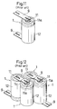
- the cell When the cylindrical cell 1 is to be used as a power source for an apparatus, generally, the cell is connected to a power source circuit in the following manner. As shown in Fig. 11, nickel plates 9 of a thickness of about 0.1 to 0.5 mm are spot-welded at one end to the projection 11a and the bottom face of the case 12, respectively. The cell is connected to the power source circuit through the nickel plates 9.
- the cylindrical cell 1 When the cylindrical cell 1 is to be used in the form of a cell pack, generally, cells are connected to each other in the following manner. As shown in Fig. 12, two adjacent cells 1 are bridged by a nickel plate 9, and the both ends of the nickel plate are spot-welded to the projection 11a of the cover 11 of one of the cells and the bottom face of the case 12 of the other cell, respectively.
- the resistances of the nickel plates 9 are not negligible, and hence the nickel plates are required to have a large thickness.
- the nickel plates 9 have a large thickness, however, it is difficult to spot-weld the plates to the cylindrical cell 1. Therefore, the increase of the thickness of a plate has a limitation.
- a prior art cell holder has a structure such as that shown in Japanese Utility Model Publication (Kokai) No. SHO60-22752.
- a plurality of cylindrical cells are arranged in such a manner that their peripheral side faces are adjacent to each other, a frame surrounds the periphery of the arranged cells, and a cover is attached to each of the end faces of the cylindrical cells.
- the frame consists of a side wall surrounding the periphery of the cells, and a number of partition walls which are inwardly projected from the side wall.
- the cylindrical cells are supported by inserting them into the spaces between the side wall and the partition walls, respectively.
- a plurality of holes are formed in a block-like frame and cylindrical cells are respectively fitted into the holes, or alternatively a large hole having a shape which is obtained by coupling such holes to each other is formed and a plurality of cylindrical cells are fitted in a bundle into the hole.
- elastic connecting plates are adequately disposed on the faces opposing the both end faces of the cylindrical cells in the frame, so that the cylindrical cells are electrically connected to each other.
- the peripheral side faces of the cylindrical cells may be covered by a film of a resin, or the like in order to ensure the electrical insulation between the cylindrical cells.
- each cylindrical cell is surrounded by the frame and the both ends are covered by the covers so that the interior of the holder is substantially hermetically sealed, and hence heat generated from the cylindrical cells during the discharging or charging process cannot be sufficiently dissipated to the exterior.
- This problem is also applicable to sealed-type cells of other types such as those of rectangular cells.
- the invention has been conducted in view of the above-discussed circumstances. It is an object of the invention to enable connecting members of a sufficiently large thickness to be respectively connected to terminals, thereby providing a cylindrical cell which is suitable for supplying a large current and a cell pack using the cylindrical cell.
- terminals are attached to the both ends of the cylindrical cell, respectively.
- a female threaded hole is opened or a male threaded portion is erected in the face portion. Consequently, an electrically conductive connecting member having a large sectional area can be screwed to the terminals by using bolts, nuts, or the like, so that cylindrical cells are assembled with a low resistance.
- Both the flat portions which are formed by separating each of the legs by a slit are spot-welded to the cover or the bottom of the case of the cylindrical cell.
- the spot welding can be surely conducted.
- the welding current can be sufficiently concentrated to the projections and hence the adhesion due to welding can be surely done.
- each leg is provided with a slit and a projection is formed on the rear face side of the flat portion, it is possible to surely conduct spot welding even when the leg has a sufficiently large thickness, thereby allowing the terminals to have a low resistance.
- a plurality of cylindrical cells constituting the cell pack are connected to each other by a connecting member which is screwed to the terminals by bolts or nuts. Therefore, the cells can be connected to each other via a connecting member of a sufficiently large thickness, so that the cell pack is assembled with a low resistance.
- a flexible material is used in the connecting member made of an electrically conductive material. Even when vibration or shock is applied to the cell pack, therefore, the force acting between the cylindrical cells is absorbed by the flexible material of the connecting member so that the bolts and nuts are prevented from loosening.
- the cell pack a plurality of cylindrical cells constituting the cell pack are held by the holder so that the face portions of the terminals on each side of the cylindrical cells to be positioned in a substantially same plane. Consequently, the terminals can be connected to each other by the shortest distance of the connecting member, whereby the increase of resistance which may be caused by a longer connecting member can be prevented from occurring.
- the cell holder comprises a pair of upper and lower plate-like supporting members, a plurality of cell holes of a predetermined depth into which a positive or negative terminal of each of sealed-type cells which are sandwiched between the pair of supporting members is to be fitted are formed in an opposing face of each of the supporting members, a terminal hole elongating to a side opposite to the opposing face is opened in a part of a bottom face of each of the cell holes, and a vent hole elongating from the opposing face to the opposite side is opened at an adequate position between the plurality of cell holes.
- the cell holder comprises a pair of upper and lower plate-like supporting members, a plurality of cell holes of a predetermined depth into which a positive or negative terminal of each of sealed-type cells which are sandwiched between the pair of supporting members is to be fitted are formed in an opposing face of each of the supporting members, a terminal hole elongating to a side opposite to the opposing face is opened in a part of a bottom face of each of the cell holes, and a vent groove elongating from the opposing face to the opposite side is formed at an adequate position of an inner peripheral face of each of the plurality of cell holes and terminal holes.
- a plurality of sealed-type cells are held between the pair of upper and lower supporting members provided with the vent hole by fitting the hermetically sealed portions at the both ends of the sealed-type cells into the cell holes, and hence heat generated from the sealed-type cells can be dissipated to the exterior via the vent hole. Since the outward-directed peripheral side faces of the sealed-type cells are exposed to the exterior between the pair of upper and lower supporting members, heat can be dissipated also from the faces.
- the terminals at the both end portions of the sealed-type cells are exposed from the upper and lower faces of the supporting members via the terminal holes, so that the sealed-type cells are connected to each other or to an external device.
- Heat generated from the sealed-type cells can be dissipated to the exterior via the vent groove which is formed at an adequate position of the inner peripheral faces of the plurality of cell holes and terminal holes and elongates from the opposing face to the opposite side.
- the grooves respectively formed on the side faces of adjacent supporting members play the same role as the vent hole. Accordingly, heat generated from the sealed-type cells can be dissipated to the exterior via the grooves.
- a connecting member through which the terminals are connected to each other so that the sealed-type cells are connected in series can have a simple shape such as a flat-plate like shape, and hence is not required to be changed in shape in accordance with a polarity.
- the cylindrical cells when the cylindrical cells are separated from each other by a sufficiently large distance, it is not required to cover the peripheral side faces of the cylindrical cells by a film of a resin, or the like.
- the electrical insulation between the cylindrical cells can be ensured by covering the peripheral side faces of the cylindrical cells by a film of a resin, or the like.
- the cooling effect can be further enhanced by forcedly producing an air flow by a cooling fan, a nozzle ejecting a cooling air, or the like.
- An embodiment of the invention is applied to the cylindrical cell 1 shown in Fig. 10.
- the kind of the cell is not restricted to a nickel-cadmium cell and a nickel-metal hydride cell.
- a high-profile terminal 2 is attached to a cover 11 on the positive terminal side
- a low-profile terminal 2 is attached to the bottom face of a case 12 on the negative terminal side.
- the terminal 2 on the positive side is configured so that the four ends of a metal plate which has a substantially cross shape and is electrically conductive are bent into legs 2a and the center face portion 2b are projected.
- a through hole is formed at the center, an end of a cylindrical female threaded hole portion 2c in which a female threaded hole is formed on the inner face is welded from the rear face side to the through hole.
- the terminal having such a configuration can be easily produced by previously forming a hole of a suitable size at the center of an area of a metal plate having a substantially cross shape where the face portion 2b is to be formed, and then attaching a weld nut so as to be aligned with the area.
- a male threaded portion is to be erected, similarly, the terminal can be easily produced with using a weld nut.
- the legs 2a which are formed by bending the four sides of the face portion 2b are further bent at the respective tip ends in the opposite direction so that the tip end portions are formed into a flat shape.
- a slit 2d is formed so as to elongate from the end of the flat shape to the basal area of the flat portion. As illustrated, the slit 2d may be formed so as to reach the end area. In some cases, the slit may be imperfectly formed in such a manner that the basal area or the tip end area of the flat portion is partly connected.
- projections 2e are formed so as to respectively project from the rear faces of the flat portion of each leg 2a which are separated by the slit 2d.
- the terminal 2 is spot-welded to the surface of the cover 11 of cylindrical cell 1 under the state where the projections 2e of each of the legs 2a at the four sides are made contact with the surface, whereby the terminal is fixedly connected to the cover.
- the welding current which flows from one of the projections 2e to the other projection 2e is blocked by the slit 2d so as to flow through the cover 11 as indicated by the arrow in Fig. 2, with the result that the spot welding between the projections 2e and the cover 11 is surely conducted.
- the tip ends of the projections 2e are made point-contact with the surface of the cover 11 so that the welding current is sufficiently concentrated to the contact portions. Even when the legs 2a have s sufficiently large thickness, therefore, it is possible to surely conduct the spot welding so that the resistance of the terminal 2 is reduced.
- the terminal 2 on the negative side is configured in the same manner as the terminal 2 shown in Figs. 1 and 2. That is, the terminal 2 is fixedly connected to the bottom face of the case 12 by spot-welding the legs 2a of the four sides to the bottom face. Since the covers 11 has the projection 11a, however, the terminal 2 on the positive side is large in step difference of the legs 2a and hence has the profile higher than the terminal 2 on the negative side.
- the terminal is attached by spot welding.
- the attachment may be conducted as required by another attaching method such as laser welding.
- a connecting member 3 is screwed to the terminal 2 by a bolt 4 as shown in Fig. 5.
- the connecting member 3 is configured by a metal plate which has a sufficiently large thickness and is electrically conductive.
- a bolt hole 3a is formed at one end portion of the plate-like shape. The screwing is conducted by placing the one end portion of the connecting member 3 on the face portion 2b of the terminal 2, inserting the bolt 4 into the bolt hole 3a of the connecting member 3 via a washer 5 and a spring washer 6 for locking, so as to pass therethrough, and fastening the bolt 4 to the female threaded hole portion 2c of the terminal 2.
- FIG 5 and 6 show the case where the connecting member 3 is screwed to the terminal 2 on the positive side.
- the positive and negative terminals of the cylindrical cell 1 can be drawn out via the connecting members 3, respectively.
- the cylindrical cell 1 is allowed to be connected to the power source circuit of the apparatus by screwing the connecting members 3 of a sufficiently large thickness to the terminals 2 on the positive and negative sides of the cell. If the material and the width and length of the plate-like shape are the same, the sectional area of each connecting member 3 is larger so that the resistance is lower, as the thickness of the member is larger. Even when the cylindrical cell 1 must supply a large current, therefore, the voltage drop and heat generation in the connecting members 3 can be reduced.
- the connecting member 7 used in the cell pack is configured by a metal plate which has a sufficiently large thickness and is electrically conductive in the same manner as the member 3 shown in Fig. 6, but a bolt hole is formed in each of the both ends of the plate-like shape.
- the screwing is conducted by respectively fastening the bolts 4 to female threaded hole portions 2c of the terminals 2 via the bolt holes, with the result that the cylindrical cells 1 are connected in series.
- the cell pack in which the two cylindrical cells 1 are connected in series is allowed to be connected to the power source circuit of the apparatus, by screwing the connecting members shown in Figs. 5 and 6 to the terminal 2 of the positive side and that of the negative side in the other side of the cylindrical cells 1.
- washers and spring washers for locking are used.
- the cylindrical cells 1 are connected to each other by the connecting member 7 of a sufficiently large thickness, and hence the voltage drop and heat generation in the connecting member 7 can be reduced.
- the center portion 7a of the connecting member 7 may be configured by a material which is flexible (for example, a net consisting of metal wires of an electrically conductive material).
- a material which is flexible for example, a net consisting of metal wires of an electrically conductive material.
- the connecting member 7 not only the center portion 7a but also the whole of the member may be configured by a flexible material. Also in the case where the whole or a part of the connecting members 3 is configured by a flexible material, the same effects can be attained.
- the cylindrical cells 1 used as the cell pack may be held by a holder 8 which causes the cells 1 to be positioned in such a manner that the face portions 2b of the terminals 2 in each side are in the substantially same plane.
- the connecting member 7 is not required to be bent or can be made flat so that the terminals 2 are connected to each other by the shortest distance. If the other conditions are the same, the resistance of the connecting member 7 is lower as the member is shorter. Consequently, the use of the holder 8 allows the connecting member 7 to connect the terminals 2 to each other by the shortest distance, thereby preventing the resistance of the connecting member 7 from being increased.
- Figs. 8 and 9 show the cases where a cell pack is configured by two cylindrical cells 1. Also in the case where three or more cylindrical cells 1 are used, a cell pack is similarly configured by connecting the cylindrical cells 1 to each other via connecting members 7. In these cell packs, in place of connecting all the cylindrical cells 1 in series, all the cylindrical cells 1 may be connected in parallel or in a combination of series and parallel connections.
- the female threaded hole portion 2c is formed in the terminal 2.
- a male threaded portion may be erected at the center of the face portion 2b of each terminal 2.
- the connecting members 3 and 7 are screwed by in respectively inserting the male threaded portions into the bolt holes 3a and 7a and fastening nuts.
- the cylindrical cells are assembled by means of low-resistance connecting members screwed to the terminals by using bolts, nuts, or the like. Even when a large current is to be supplied, the voltage drop and heat generation in the connecting members can be suppressed so that the most of the cell performance can be exerted.
- the formation of the slit and the projection in the leg of each terminal allows the terminal to be surely subjected to the spot welding.
- the cylindrical cells are connected to each other by connecting members of a sufficiently large thickness so that the cell pack can be assembled with a low resistance, and hence the most of the performance of each cell can be exerted.
- the use of a flexible material in the connecting member enables forces acting between the cells to be buffered, thereby preventing the bolts or nuts used in the connection of the cells from loosening.
- the cells can be connected to each other by connecting members by the shortest distance, and hence the resistances of the connecting members can be further reduced.
- the cell holder of the invention in which six cylindrical cells each consisting of a nickel-cadmium cell or a nickel-metal hydride cell are held will be described.
- the kind and shape of the cell are not restricted to the above, conventional manganese cells may be used, and sealed-type cells of other types such as those of rectangular cells may be used.
- the six cylindrical cells 1 are arranged in such a manner that positive and negative terminals of adjacent cells are directed in a vertically inverted manner, and into two rows each consisting of three cells.
- terminals 2 for the positive and negative sides are attached to the both ends of a cylindrical shape, respectively.
- the terminals 2 are electrically conductive connection members in each of which the connecting face where a female threaded hole is opened at the center is supported by legs of the four sides so as to be projected and which are fixed by spot-welding to end faces of the cylindrical shape of the positive and negative sides of the cylindrical cell 1.
- the terminal 2 on the positive side is attached so that a projection (not shown) for housing a safety valve for gas releasing which is disposed on the end face of the cylindrical shape on the positive side of the cylindrical cell 1, and hence is taller than the terminal 2 on the negative side.
- the six cylindrical cells 1 are sandwiched between a pair of upper and lower supporting members 20 which are made of an insulating synthetic resin plate having a substantially square shape and have the same shape. As far as the problem of electric insulation is solved, any material may be used.
- the supporting members 20 are used while being disposed with opposing each other.
- cell holes 20a having a diameter which is equal to or slightly greater than that of the cylindrical portion of the cylindrical cell 1 are formed in the surface which functions as the opposing face, into two rows each consisting of three holes.
- the cell holes 20a have two kinds of depths which are different from each other by the difference in height of the terminals 2 of the cylindrical cell 1, and are arranged in such a manner that adjacent ones have different depths.
- the cylindrical portion on the positive terminal side of the cylindrical cell 1 is fitted into one of the shallow cell holes 20a, and that on the negative terminal side is fitted into one of the deep cell holes 20a.
- a terminal hole 20b which is smaller in diameter than the cell hole 20a is opened so as to reach the rear face.
- Each terminal hole 20b is disposed so that, when the cylindrical portion of the cylindrical cell 1 is fitted into the cell hole 20a, the projection of the terminal 2 enters the terminal hole, thereby allowing the shoulder of the cylindrical portion to make contact with the bottom face of the cell hole 20a. Since the cell holes 20a into which the cylindrical portions on the positive and negative terminal sides are fitted are different in depth from each other, the connecting faces at the tip ends of the terminals 2 of both the positive and negative sides are substantially flush with the rear faces of the respective supporting members 20.
- each of the supporting members 20 a vent hole 20c elongating from the surface to the rear face is opened in each of two areas which are respectively surrounded by four cell holes 20a.
- a groove 20d which elongates from the surface to the rear face is formed.
- the four edges of each of the square supporting members 20 are cut by an arcuate convex shape so as to form rounded portions 20e.
- the pair of upper and lower supporting members 20 which are configured as described above are disposed with being directed so that, as shown in Fig. 17, their surfaces oppose each other and the opposing cell holes 20a are different in depth from each other.
- the cylindrical portions on the positive and negative terminal sides of six cylindrical cells 1 are fitted into the cell holes 20a of the upper and lower supporting members 20, respectively.
- the six cylindrical cells 1 are sandwiched between the upper and lower supporting members 20 and the terminals 2 of the cylindrical cells 1 are exposed from the respective terminal holes 20b.
- connecting members 3 which are made of an electrically conductive material and have a flat plate-like shape are placed between terminals 2 which are adjacent to each other in the row direction, and then screwed to the terminals by bolts 4, and, on the side of the rear face of the lower supporting member 20 (on the face which is directed downward), similar connecting members 3 are placed between terminals 2 which are adjacent to each other and in different rows, and then screwed to the terminals by bolts 4.
- FIG. 18 all the six cylindrical cells 1 between the terminals 2 exposed from the two terminal holes 20b of the upper supporting member 20 in which the connecting members 3 are not attached are connected in series.
- the screwing of the connecting members 3 by the bolts 4 is conducted by causing the male threaded portions of the bolts 4 to respectively pass through the threaded holes formed at the both ends of the connecting members 3 and fastening the bolts to the connecting faces of the terminals 2.
- the connecting faces of both the terminals 2 are substantially flush with the rear face of the supporting member 20, and hence the flat-plate like connecting member 3 can be placed as it is at a position which substantially contacts with the rear face of the supporting member 20 or in parallel with the face, and screwed by the bolts 4.
- the screwing of the connecting members 3 causes the upper and lower supporting members 20 to be integrally fixed to the six cylindrical cells 1.
- the heat dissipation of the cylindrical cells 1 is accelerated by the vent holes 20c and the like, whereby the temperature rise of the cylindrical cells 1 can be suppressed so as not to exceed the specified range.
- the ventilation due to the vent holes 20c and the like is conducted by natural convention. Particularly when the amount of generated heat is large, the ventilation may be forcedly conducted by using a fan or the like.
- edge grooves 20g which are formed by cutting the supporting member into a rounded concave shape may be formed.
- a through hole 21 at each edge area where the four cell holders are made contact with each other is configured as a cylindrical hole in the same manner as the vent holes 20c, with the result that the through hole 21 can be made coincident in shape with the original vent holes 20c and the through holes 21 formed by the grooves 20d.
- projections 20f which are projected by the same height may be formed in the peripheral edge portions of the face of each supporting member 20 which is opposite to the opposing face, the vent holes 20c, the vent grooves 20d, and the rounded portions 20e.
- the provision of the projections 20f can block the connecting members 3 from being rotated when they are detached, thereby preventing adjacent cells from being short-circuited, and a short circuit from occurring when cell packs are stacked.
- the projections 20f are not required to be formed at all the peripheral edges, but adequately disposed at two or three positions of the supporting member.
- vent holes 20c are formed at appropriate positions between the plurality of cell holes 20a.
- vent grooves 20h which elongate from the opposing face to the opposite side may be formed at appropriate positions of the inner peripheral faces of the plurality of cell holes 20a and terminal holes 20b.
- the cell holder holds six cylindrical cells 1.
- the number of cylindrical cells 1 which can be held by the holder can be set arbitrarily.
- the cell holes and the like in each supporting member 20 are formed in accordance with the number of the cylindrical cells 1 and the manner of arrangement.
- heat generated from cylindrical cells can be dissipated to the exterior via the vent holes of the supporting members and the exposed side portions between the upper and lower supporting members. Consequently, the temperature rise of the cylindrical cells can be suppressed by means of natural convection or forced ventilation. Also when a plurality of cell holders in each of which cylindrical cells are held by a pair of supporting members are arranged, heat can be dissipated to the exterior via the grooves between adjacent supporting members. Even in the case where a number of cylindrical cells are densely packed, therefore, the temperature rise can be surely suppressed. Furthermore, even in the case where the terminals of cylindrical cells are different in height depending on the polarity, the terminals can be easily connected to each other by a connecting member of a shape such as a flat-plate like shape.
Landscapes
- Chemical & Material Sciences (AREA)
- Chemical Kinetics & Catalysis (AREA)
- Electrochemistry (AREA)
- General Chemical & Material Sciences (AREA)
- Engineering & Computer Science (AREA)
- Manufacturing & Machinery (AREA)
- Battery Mounting, Suspending (AREA)
- Connection Of Batteries Or Terminals (AREA)
Abstract
Description
- The invention relates to a cylindrical cell which has a cylindrical shape, to a cell pack in which a plurality of the cylindrical cells are connected to each other, and to a cell holder which holds in a bundle a plurality of sealed-type cells.
- A nickel-cadmium cell and a nickel-metal hydride cell which are rechargeable are widely employed as a battery power source for a portable apparatus. Such a nickel-cadmium cell or a nickel-metal hydride cell is used mainly in the form of a cylindrical cell which has a cylindrical shape. In a portable apparatus, such a cylindrical cell is used singly or in the form of a cell pack in which a plurality of cells are connected.
- As shown in Fig. 10, a
cylindrical cell 1 has a structure in which one end of acylindrical case 12 containing cell materials is closed by acover 11 via a packing and then caulked. Aprojection 11a is formed in thecover 11, and a safety valve for releasing gasses is disposed in theprojection 11a. In thecylindrical cell 1, generally, thecover 11 having theprojection 11a is connected to a positive electrode, and thecase 12 which covers the peripheral side face and the bottom face is connected to a negative electrode. - When the
cylindrical cell 1 is to be used as a power source for an apparatus, generally, the cell is connected to a power source circuit in the following manner. As shown in Fig. 11,nickel plates 9 of a thickness of about 0.1 to 0.5 mm are spot-welded at one end to theprojection 11a and the bottom face of thecase 12, respectively. The cell is connected to the power source circuit through thenickel plates 9. When thecylindrical cell 1 is to be used in the form of a cell pack, generally, cells are connected to each other in the following manner. As shown in Fig. 12, twoadjacent cells 1 are bridged by anickel plate 9, and the both ends of the nickel plate are spot-welded to theprojection 11a of thecover 11 of one of the cells and the bottom face of thecase 12 of the other cell, respectively. - In the case where the
cylindrical cell 1 must supply a large current, the resistances of thenickel plates 9 are not negligible, and hence the nickel plates are required to have a large thickness. When thenickel plates 9 have a large thickness, however, it is difficult to spot-weld the plates to thecylindrical cell 1. Therefore, the increase of the thickness of a plate has a limitation. - In the prior art, therefore, the voltage drop and heat generation in the
nickel plates 9 are inevitably increased in magnitude when thecylindrical cell 1 supplies a large current, thereby producing a problem in that the cell performance cannot be sufficiently exerted. - A prior art cell holder has a structure such as that shown in Japanese Utility Model Publication (Kokai) No. SHO60-22752. In the cell holder, a plurality of cylindrical cells are arranged in such a manner that their peripheral side faces are adjacent to each other, a frame surrounds the periphery of the arranged cells, and a cover is attached to each of the end faces of the cylindrical cells. The frame consists of a side wall surrounding the periphery of the cells, and a number of partition walls which are inwardly projected from the side wall. The cylindrical cells are supported by inserting them into the spaces between the side wall and the partition walls, respectively. In some cases, a plurality of holes are formed in a block-like frame and cylindrical cells are respectively fitted into the holes, or alternatively a large hole having a shape which is obtained by coupling such holes to each other is formed and a plurality of cylindrical cells are fitted in a bundle into the hole. In the covers, elastic connecting plates are adequately disposed on the faces opposing the both end faces of the cylindrical cells in the frame, so that the cylindrical cells are electrically connected to each other.
- In a cell pack using such a cell holder, when required, the peripheral side faces of the cylindrical cells may be covered by a film of a resin, or the like in order to ensure the electrical insulation between the cylindrical cells.
- When a cell is discharged, heat is generated as a result of an internal electrochemical reaction and electric resistance. In the case of a heavy current drain, particularly, the amount of generated heat is increased. In a sealed-type secondary cell such as a nickel cadmium cell or a nickel-metal hydride cell, the heat generation occurs also when the cell is charged. When the temperature of the cell is raised as a result of the heat generation, self-discharge may reduce the cell capacity or shorten the service life of the cell. Therefore, it is previously determined that such a cell is used in a temperature range of -10 to 60°C during a discharging process and 0 to 35°C during a charging process.
- In the prior art cell holder, however, each cylindrical cell is surrounded by the frame and the both ends are covered by the covers so that the interior of the holder is substantially hermetically sealed, and hence heat generated from the cylindrical cells during the discharging or charging process cannot be sufficiently dissipated to the exterior. This produces a problem in that the temperature of the cylindrical cells may be raised to a level higher than the specified range. This problem is also applicable to sealed-type cells of other types such as those of rectangular cells.
- The invention has been conducted in view of the above-discussed circumstances. It is an object of the invention to enable connecting members of a sufficiently large thickness to be respectively connected to terminals, thereby providing a cylindrical cell which is suitable for supplying a large current and a cell pack using the cylindrical cell.
- It is another object of the invention to provide a cylindrical cell which, in order to solve the above-discussed problems, comprises a cover connected to one electrode and a bottomed cylindrical case connected to the other electrode, and in which terminals made of an electrically conductive material and having a face portion where a female threaded hole is opened or a male threaded portion is erected are respectively fixedly connected to a cover and a bottom face of a case via legs which support the face portion.
- It is a further object of the invention to provide a cylindrical cell in which tip ends of the legs of the terminals are formed into a flat-plate like shape, each of the flat portions of the legs is provided with at least one of a slit and a projection which is projected from a rear face of the flat portion, and the legs are fixedly connected by spot-welding the flat portions of the legs to the cover and the bottom face of the case.
- It is a still further object of the invention to provide a cell pack in which a plurality of the cylindrical cells are arranged side-by-side, a connecting member in which bolt holes are opened at both end portions and which is made of an electrically conductive material is used, and bolts are respectively fitted into the both bolt holes of the connecting member and the bolts are fastened to female threaded holes which are opened in face portions of terminals of different cylindrical cells, or male threaded portions erected on face portions of terminals of different cylindrical cells are respectively fitted into the both bolt holes of the connecting member and nuts are respectively fastened to the male threaded portions, or a bolt is fitted into one of the bolt holes of the connecting member and the bolt is fastened to a female threaded hole which is opened in a face portion of a terminal of one of the cylindrical cells and a male threaded portion erected on a face portion of a terminal of another one of cylindrical cells is fitted into the other both bolt hole and a nut is fastened to the male threaded portion, thereby connecting the cylindrical cells with each other.
- It is a still further object of the invention to provide a cell pack in which a part or whole of the connecting member which is made of an electrically conductive material is configured by a flexible material.
- It is a still further object of the invention to provide a cell pack in which the cylindrical cells are held by a holder which causes the face portions of the terminals on each side of the cylindrical cells to be positioned in a substantially same plane.
- According to the thus configured cylindrical cell, terminals are attached to the both ends of the cylindrical cell, respectively. In each of the terminals, a female threaded hole is opened or a male threaded portion is erected in the face portion. Consequently, an electrically conductive connecting member having a large sectional area can be screwed to the terminals by using bolts, nuts, or the like, so that cylindrical cells are assembled with a low resistance.
- Both the flat portions which are formed by separating each of the legs by a slit are spot-welded to the cover or the bottom of the case of the cylindrical cell. In this case, since the welding current of a sufficient level flows between the two faces via the cover or the bottom of the case, the spot welding can be surely conducted. When projections projected from the rear faces of the flat portions are formed, the welding current can be sufficiently concentrated to the projections and hence the adhesion due to welding can be surely done.
- In the case where the flat portion of each leg is provided with a slit and a projection is formed on the rear face side of the flat portion, it is possible to surely conduct spot welding even when the leg has a sufficiently large thickness, thereby allowing the terminals to have a low resistance.
- According to the cell pack, a plurality of cylindrical cells constituting the cell pack are connected to each other by a connecting member which is screwed to the terminals by bolts or nuts. Therefore, the cells can be connected to each other via a connecting member of a sufficiently large thickness, so that the cell pack is assembled with a low resistance.
- According to the cell pack, a flexible material is used in the connecting member made of an electrically conductive material. Even when vibration or shock is applied to the cell pack, therefore, the force acting between the cylindrical cells is absorbed by the flexible material of the connecting member so that the bolts and nuts are prevented from loosening.
- According to the cell pack, a plurality of cylindrical cells constituting the cell pack are held by the holder so that the face portions of the terminals on each side of the cylindrical cells to be positioned in a substantially same plane. Consequently, the terminals can be connected to each other by the shortest distance of the connecting member, whereby the increase of resistance which may be caused by a longer connecting member can be prevented from occurring.
- It is a still further object of the invention to provide a cell holder in which upper and lower end portions of sealed-type cells are held by a pair of supporting members provided with a vent hole, thereby allowing heat generated from the sealed-type cells to be dissipated to the exterior via the vent hole.
- It is a still further object of the invention to provide a cell holder in which, in order to solve the above-discussed problems, the cell holder comprises a pair of upper and lower plate-like supporting members, a plurality of cell holes of a predetermined depth into which a positive or negative terminal of each of sealed-type cells which are sandwiched between the pair of supporting members is to be fitted are formed in an opposing face of each of the supporting members, a terminal hole elongating to a side opposite to the opposing face is opened in a part of a bottom face of each of the cell holes, and a vent hole elongating from the opposing face to the opposite side is opened at an adequate position between the plurality of cell holes.
- It is a still further object of the invention to provide a cell holder in which the cell holder comprises a pair of upper and lower plate-like supporting members, a plurality of cell holes of a predetermined depth into which a positive or negative terminal of each of sealed-type cells which are sandwiched between the pair of supporting members is to be fitted are formed in an opposing face of each of the supporting members, a terminal hole elongating to a side opposite to the opposing face is opened in a part of a bottom face of each of the cell holes, and a vent groove elongating from the opposing face to the opposite side is formed at an adequate position of an inner peripheral face of each of the plurality of cell holes and terminal holes.
- It is a still further object of the invention to provide a cell holder in which a groove elongating from the opposing face to the opposite side is formed at an appropriate position of a side face of each of the supporting members.
- It is a still further object of the invention to provide a cell holder in which terminals which are different in height from each other are disposed at both ends of each of the sealed-type cells, and the cell holes are formed at depths which are different from each other by a difference in height of the terminals in accordance with a polarity.
- It is a still further object of the invention to provide a cell holder in which a projection is formed in at least one of a peripheral end portion of a face opposite to the opposing face of each of the supporting members, and a peripheral end portion of the vent hole or vent groove.
- According to the thus configured cell holder, a plurality of sealed-type cells are held between the pair of upper and lower supporting members provided with the vent hole by fitting the hermetically sealed portions at the both ends of the sealed-type cells into the cell holes, and hence heat generated from the sealed-type cells can be dissipated to the exterior via the vent hole. Since the outward-directed peripheral side faces of the sealed-type cells are exposed to the exterior between the pair of upper and lower supporting members, heat can be dissipated also from the faces. The terminals at the both end portions of the sealed-type cells are exposed from the upper and lower faces of the supporting members via the terminal holes, so that the sealed-type cells are connected to each other or to an external device.
- Heat generated from the sealed-type cells can be dissipated to the exterior via the vent groove which is formed at an adequate position of the inner peripheral faces of the plurality of cell holes and terminal holes and elongates from the opposing face to the opposite side.
- When a plurality of cell holders in each of which a plurality of sealed-type cells are held by the pair of upper and lower supporting members are arranged side-by-side, the grooves respectively formed on the side faces of adjacent supporting members play the same role as the vent hole. Accordingly, heat generated from the sealed-type cells can be dissipated to the exterior via the grooves.
- When sealed-type cells are arranged in such a manner that the polarities of adjacent cells are positionally inverted, the tip ends of the both terminals of the sealed-type cells can be made flush with each other because the cylindrical portions of the sealed-type cells are fitted into the cell holes at depths which are different from each other. Consequently, a connecting member through which the terminals are connected to each other so that the sealed-type cells are connected in series can have a simple shape such as a flat-plate like shape, and hence is not required to be changed in shape in accordance with a polarity. When the connecting member is fixedly connected to the terminals by screwing or the like, the pair of upper and lower supporting members can be surely fixed to a plurality of sealed-type cells.
- Furthermore, it is possible to block a connecting plate from being rotated when it is detached, thereby preventing adjacent cells from being short-circuited, and a short circuit from occurring when cell packs are stacked.
- In the cell pack using the cell holder of the invention, when the cylindrical cells are separated from each other by a sufficiently large distance, it is not required to cover the peripheral side faces of the cylindrical cells by a film of a resin, or the like. When the cylindrical cells are not separated from each other by a sufficiently large distance, the electrical insulation between the cylindrical cells can be ensured by covering the peripheral side faces of the cylindrical cells by a film of a resin, or the like.
- On the other hand, in the cell pack using the cell holder of the invention, the cooling effect can be further enhanced by forcedly producing an air flow by a cooling fan, a nozzle ejecting a cooling air, or the like.
-
- Fig. 1 shows an embodiment of the invention and is a partial enlarged perspective view showing a terminal attached to the positive terminal of a cylindrical cell;
- Fig. 2 shows an embodiment of the invention and is a longitudinal section view of the vicinity of a leg of the terminal shown in Fig. 1;
- Fig. 3 shows an embodiment of the invention and is a perspective view of the whole of the cylindrical cell as viewed from the positive terminal side;
- Fig. 4 shows an embodiment of the invention and is a perspective view of the whole of the cylindrical cell as viewed from the negative terminal side;
- Fig. 5 shows an embodiment of the invention and is a partial enlarged perspective view showing the case where a connecting plate is screwed to the terminal of the cylindrical cell;
- Fig. 6 shows an embodiment of the invention and is an exploded perspective view of the structure of Fig. 5;
- Fig. 7 shows an embodiment of the invention and is a perspective view of the cylindrical cell in the state where a connecting plate is screwed to the terminal of the cylindrical cell;
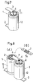
- Fig. 8 shows an embodiment of the invention, Fig. 8(A) is a perspective view of the whole of the cylindrical cell in the state where a connecting member is screwed to the terminal, and Fig. 8(B) is a perspective view showing a modification of the connecting member;
- Fig. 9 shows an embodiment of the invention and is a side view showing the case where cylindrical cells constituting a cell pack are held by a holder;
- Fig. 10 is a perspective view showing the configuration of a prior art cylindrical cell;
- Fig. 11 is a perspective view showing the whole of a state where a nickel plate is attached to the prior art cylindrical cell;
- Fig. 12 is a perspective view showing the whole of a prior art cell pack configured by four prior art cylindrical cells;
- Fig. 13 shows an embodiment of the invention and is a perspective view showing the assembly of a cell holder;
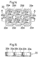
- Fig. 14 shows an embodiment of the invention and is a plan view of a supporting member;
- Fig. 15 shows an embodiment of the invention and is a section view taken along line A-A of Fig. 14;
- Fig. 16 shows an embodiment of the invention and is a section view taken along line B-B of Fig. 14;
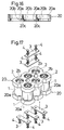
- Fig. 17 shows an embodiment of the invention and is a perspective view showing the assembly state where a connecting plate is screwed to the cell holder;
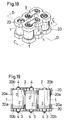
- Fig. 18 shows an embodiment of the invention and is a perspective view of a cell holder;
- Fig. 19 shows an embodiment of the invention and is a section view taken along line C-C of Fig. 18;
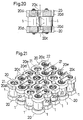
- Fig. 20 shows an embodiment of the invention and is a section view taken along line D-D of Fig. 18;
- Fig. 21 shows an embodiment of the invention and is a partial perspective view showing the case where a plurality of cell holders are arranged;
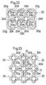
- Fig. 22 shows an embodiment of the invention and is a plan view showing another shape of the supporting member;
- Fig. 23 shows an embodiment of the invention and is a partial plan view showing an edge in the case where a plurality of the supporting members shown in Fig. 22 are arranged;
- Fig. 24 shows an embodiment of the invention and is a perspective view showing the case where projections are formed in the periphery of the face opposite to the opposing face of the supporting member, and that of a vent hole or a vent groove; and
- Fig. 25 shows an embodiment of the invention and is a perspective view showing the case where a vent groove is formed in the inner peripheral faces of cell holes and terminal holes.
- Hereinafter, embodiments of the invention will be described with reference to the accompanying drawings.
- In the description of the embodiments, components having the same functions as those of the prior art example shown in Fig. 10 are designated by the same reference numerals and their description is omitted.
- An embodiment of the invention is applied to the
cylindrical cell 1 shown in Fig. 10. However, the kind of the cell is not restricted to a nickel-cadmium cell and a nickel-metal hydride cell. In thecylindrical cell 1, as shown in Fig. 3, a high-profile terminal 2 is attached to acover 11 on the positive terminal side, and, as shown in Fig. 4, a low-profile terminal 2 is attached to the bottom face of acase 12 on the negative terminal side. - As shown in Fig. 1, the
terminal 2 on the positive side is configured so that the four ends of a metal plate which has a substantially cross shape and is electrically conductive are bent intolegs 2a and thecenter face portion 2b are projected. In theface portion 2b of theterminal 2, a through hole is formed at the center, an end of a cylindrical female threadedhole portion 2c in which a female threaded hole is formed on the inner face is welded from the rear face side to the through hole. - The terminal having such a configuration can be easily produced by previously forming a hole of a suitable size at the center of an area of a metal plate having a substantially cross shape where the
face portion 2b is to be formed, and then attaching a weld nut so as to be aligned with the area. In the case where a male threaded portion is to be erected, similarly, the terminal can be easily produced with using a weld nut. - The
legs 2a which are formed by bending the four sides of theface portion 2b are further bent at the respective tip ends in the opposite direction so that the tip end portions are formed into a flat shape. Aslit 2d is formed so as to elongate from the end of the flat shape to the basal area of the flat portion. As illustrated, theslit 2d may be formed so as to reach the end area. In some cases, the slit may be imperfectly formed in such a manner that the basal area or the tip end area of the flat portion is partly connected. As shown in Fig. 2,projections 2e are formed so as to respectively project from the rear faces of the flat portion of eachleg 2a which are separated by theslit 2d. Theterminal 2 is spot-welded to the surface of thecover 11 ofcylindrical cell 1 under the state where theprojections 2e of each of thelegs 2a at the four sides are made contact with the surface, whereby the terminal is fixedly connected to the cover. In the spot welding, therefore, the welding current which flows from one of theprojections 2e to theother projection 2e is blocked by theslit 2d so as to flow through thecover 11 as indicated by the arrow in Fig. 2, with the result that the spot welding between theprojections 2e and thecover 11 is surely conducted. The tip ends of theprojections 2e are made point-contact with the surface of thecover 11 so that the welding current is sufficiently concentrated to the contact portions. Even when thelegs 2a have s sufficiently large thickness, therefore, it is possible to surely conduct the spot welding so that the resistance of theterminal 2 is reduced. - Also, the
terminal 2 on the negative side is configured in the same manner as theterminal 2 shown in Figs. 1 and 2. That is, theterminal 2 is fixedly connected to the bottom face of thecase 12 by spot-welding thelegs 2a of the four sides to the bottom face. Since thecovers 11 has theprojection 11a, however, theterminal 2 on the positive side is large in step difference of thelegs 2a and hence has the profile higher than theterminal 2 on the negative side. - In the embodiment, the terminal is attached by spot welding. Alternatively, the attachment may be conducted as required by another attaching method such as laser welding.
- When the thus configured
cylindrical cell 1 is to be singly connected to a power source circuit of an apparatus, a connectingmember 3 is screwed to theterminal 2 by abolt 4 as shown in Fig. 5. The connectingmember 3 is configured by a metal plate which has a sufficiently large thickness and is electrically conductive. As shown in Fig. 6, abolt hole 3a is formed at one end portion of the plate-like shape. The screwing is conducted by placing the one end portion of the connectingmember 3 on theface portion 2b of theterminal 2, inserting thebolt 4 into thebolt hole 3a of the connectingmember 3 via a washer 5 and a spring washer 6 for locking, so as to pass therethrough, and fastening thebolt 4 to the female threadedhole portion 2c of theterminal 2. Figs. 5 and 6 show the case where the connectingmember 3 is screwed to theterminal 2 on the positive side. When another connectingmember 3 is screwed to theterminal 2 on the negative side in the same manner, the positive and negative terminals of thecylindrical cell 1 can be drawn out via the connectingmembers 3, respectively. - As a result, according to the embodiment, the
cylindrical cell 1 is allowed to be connected to the power source circuit of the apparatus by screwing the connectingmembers 3 of a sufficiently large thickness to theterminals 2 on the positive and negative sides of the cell. If the material and the width and length of the plate-like shape are the same, the sectional area of each connectingmember 3 is larger so that the resistance is lower, as the thickness of the member is larger. Even when thecylindrical cell 1 must supply a large current, therefore, the voltage drop and heat generation in the connectingmembers 3 can be reduced. - When the thus configured
cylindrical cell 1 is used as an elementary cell of a cell pack, as shown in (A) of Fig. 8, twocylindrical cells 1 are arranged side-by-side while the positive terminal side of one of thecylindrical cells 1 and the negative side of the othercylindrical cell 1 are directed to the same direction. A connectingmember 7 is connected between theterminal 2 of the positive side and that of the negative side in one side of thecylindrical cells 1, and screwed to the terminals bybolts 4. Specifically, the connectingmember 7 used in the cell pack is configured by a metal plate which has a sufficiently large thickness and is electrically conductive in the same manner as themember 3 shown in Fig. 6, but a bolt hole is formed in each of the both ends of the plate-like shape. The screwing is conducted by respectively fastening thebolts 4 to female threadedhole portions 2c of theterminals 2 via the bolt holes, with the result that thecylindrical cells 1 are connected in series. The cell pack in which the twocylindrical cells 1 are connected in series is allowed to be connected to the power source circuit of the apparatus, by screwing the connecting members shown in Figs. 5 and 6 to theterminal 2 of the positive side and that of the negative side in the other side of thecylindrical cells 1. Also in this screwing of the connectingmember 7 by using thebolts 4, in the same manner as the case of the connectingmember 3, washers and spring washers for locking are used. - As a result, according to the embodiment, in the case where the
cylindrical cells 1 are used in the form of a cell pack, thecylindrical cells 1 are connected to each other by the connectingmember 7 of a sufficiently large thickness, and hence the voltage drop and heat generation in the connectingmember 7 can be reduced. - As shown in (B) of Fig. 8, alternatively, the
center portion 7a of the connectingmember 7 may be configured by a material which is flexible (for example, a net consisting of metal wires of an electrically conductive material). In the alternative, even when vibration or shock is applied to the cell pack, the force acting between thecylindrical cells 1 is absorbed by the flexibility of the connectingmember 7, and hence thebolts 4 are prevented from loosening. In the connectingmember 7, not only thecenter portion 7a but also the whole of the member may be configured by a flexible material. Also in the case where the whole or a part of the connectingmembers 3 is configured by a flexible material, the same effects can be attained. - As shown in Fig. 9, the
cylindrical cells 1 used as the cell pack may be held by aholder 8 which causes thecells 1 to be positioned in such a manner that theface portions 2b of theterminals 2 in each side are in the substantially same plane. In this case, the connectingmember 7 is not required to be bent or can be made flat so that theterminals 2 are connected to each other by the shortest distance. If the other conditions are the same, the resistance of the connectingmember 7 is lower as the member is shorter. Consequently, the use of theholder 8 allows the connectingmember 7 to connect theterminals 2 to each other by the shortest distance, thereby preventing the resistance of the connectingmember 7 from being increased. - Figs. 8 and 9 show the cases where a cell pack is configured by two
cylindrical cells 1. Also in the case where three or morecylindrical cells 1 are used, a cell pack is similarly configured by connecting thecylindrical cells 1 to each other via connectingmembers 7. In these cell packs, in place of connecting all thecylindrical cells 1 in series, all thecylindrical cells 1 may be connected in parallel or in a combination of series and parallel connections. - In the embodiments described above, the female threaded
hole portion 2c is formed in theterminal 2. Alternatively, a male threaded portion may be erected at the center of theface portion 2b of eachterminal 2. In the alternative, the connectingmembers - As apparent from the above description, in the cylindrical cell of the invention, the cylindrical cells are assembled by means of low-resistance connecting members screwed to the terminals by using bolts, nuts, or the like. Even when a large current is to be supplied, the voltage drop and heat generation in the connecting members can be suppressed so that the most of the cell performance can be exerted. The formation of the slit and the projection in the leg of each terminal allows the terminal to be surely subjected to the spot welding. Also in the case where the cylindrical cell is used in a cell pack, the cylindrical cells are connected to each other by connecting members of a sufficiently large thickness so that the cell pack can be assembled with a low resistance, and hence the most of the performance of each cell can be exerted. The use of a flexible material in the connecting member enables forces acting between the cells to be buffered, thereby preventing the bolts or nuts used in the connection of the cells from loosening. When the cylindrical cells of the cell pack are held by the holder, the cells can be connected to each other by connecting members by the shortest distance, and hence the resistances of the connecting members can be further reduced.
- Next, an embodiment of the cell holder of the invention in which six cylindrical cells each consisting of a nickel-cadmium cell or a nickel-metal hydride cell are held will be described. In the invention, however, the kind and shape of the cell are not restricted to the above, conventional manganese cells may be used, and sealed-type cells of other types such as those of rectangular cells may be used. As shown in Fig. 13, the six
cylindrical cells 1 are arranged in such a manner that positive and negative terminals of adjacent cells are directed in a vertically inverted manner, and into two rows each consisting of three cells. In each of thecylindrical cells 1,terminals 2 for the positive and negative sides are attached to the both ends of a cylindrical shape, respectively. Theterminals 2 are electrically conductive connection members in each of which the connecting face where a female threaded hole is opened at the center is supported by legs of the four sides so as to be projected and which are fixed by spot-welding to end faces of the cylindrical shape of the positive and negative sides of thecylindrical cell 1. Theterminal 2 on the positive side is attached so that a projection (not shown) for housing a safety valve for gas releasing which is disposed on the end face of the cylindrical shape on the positive side of thecylindrical cell 1, and hence is taller than theterminal 2 on the negative side. - The six
cylindrical cells 1 are sandwiched between a pair of upper and lower supportingmembers 20 which are made of an insulating synthetic resin plate having a substantially square shape and have the same shape. As far as the problem of electric insulation is solved, any material may be used. The supportingmembers 20 are used while being disposed with opposing each other. In each of the supportingmembers 20, as shown in Figs. 14 to 16,cell holes 20a having a diameter which is equal to or slightly greater than that of the cylindrical portion of thecylindrical cell 1 are formed in the surface which functions as the opposing face, into two rows each consisting of three holes. The cell holes 20a have two kinds of depths which are different from each other by the difference in height of theterminals 2 of thecylindrical cell 1, and are arranged in such a manner that adjacent ones have different depths. The cylindrical portion on the positive terminal side of thecylindrical cell 1 is fitted into one of theshallow cell holes 20a, and that on the negative terminal side is fitted into one of thedeep cell holes 20a. In the bottom face of eachcell hole 20a, aterminal hole 20b which is smaller in diameter than thecell hole 20a is opened so as to reach the rear face. Eachterminal hole 20b is disposed so that, when the cylindrical portion of thecylindrical cell 1 is fitted into thecell hole 20a, the projection of theterminal 2 enters the terminal hole, thereby allowing the shoulder of the cylindrical portion to make contact with the bottom face of thecell hole 20a. Since the cell holes 20a into which the cylindrical portions on the positive and negative terminal sides are fitted are different in depth from each other, the connecting faces at the tip ends of theterminals 2 of both the positive and negative sides are substantially flush with the rear faces of the respective supportingmembers 20. - In each of the supporting
members 20, avent hole 20c elongating from the surface to the rear face is opened in each of two areas which are respectively surrounded by fourcell holes 20a. On the side faces of the supportingmembers 20 and betweenadjacent cell holes 20a, agroove 20d which elongates from the surface to the rear face is formed. The four edges of each of the square supportingmembers 20 are cut by an arcuate convex shape so as to formrounded portions 20e. - The pair of upper and lower supporting
members 20 which are configured as described above are disposed with being directed so that, as shown in Fig. 17, their surfaces oppose each other and the opposingcell holes 20a are different in depth from each other. As indicated by the arrows in Fig. 13, the cylindrical portions on the positive and negative terminal sides of sixcylindrical cells 1 are fitted into the cell holes 20a of the upper and lower supportingmembers 20, respectively. As a result, as shown in Fig. 17, the sixcylindrical cells 1 are sandwiched between the upper and lower supportingmembers 20 and theterminals 2 of thecylindrical cells 1 are exposed from the respectiveterminal holes 20b. On the side of the rear face of the upper supporting member 20 (on the face which is directed upward), connectingmembers 3 which are made of an electrically conductive material and have a flat plate-like shape are placed betweenterminals 2 which are adjacent to each other in the row direction, and then screwed to the terminals bybolts 4, and, on the side of the rear face of the lower supporting member 20 (on the face which is directed downward), similar connectingmembers 3 are placed betweenterminals 2 which are adjacent to each other and in different rows, and then screwed to the terminals bybolts 4. As a result, as shown in Fig. 18, all the sixcylindrical cells 1 between theterminals 2 exposed from the twoterminal holes 20b of the upper supportingmember 20 in which the connectingmembers 3 are not attached are connected in series. The screwing of the connectingmembers 3 by thebolts 4 is conducted by causing the male threaded portions of thebolts 4 to respectively pass through the threaded holes formed at the both ends of the connectingmembers 3 and fastening the bolts to the connecting faces of theterminals 2. In this case, as shown in Fig. 19, the connecting faces of both theterminals 2 are substantially flush with the rear face of the supportingmember 20, and hence the flat-plate like connectingmember 3 can be placed as it is at a position which substantially contacts with the rear face of the supportingmember 20 or in parallel with the face, and screwed by thebolts 4. The screwing of the connectingmembers 3 causes the upper and lower supportingmembers 20 to be integrally fixed to the sixcylindrical cells 1. - In the cell holder in which the six
cylindrical cells 1 are held by the pair of supportingmembers 20 as described above, as indicated by the arrows in Fig. 20, ventilation is enabled between the exterior and the vicinity of the inward-directed peripheral side faces of thecylindrical cells 1, via the vent holes 20c of the supportingmembers 20. Consequently, heat generated from thecylindrical cells 1 can be rapidly dissipated to the exterior. The outward-directed peripheral side faces of thecylindrical cells 1 which are arranged in two rows are exposed as they are between the upper and lower supportingmembers 20, so that heat can be dissipated also from the faces. Accordingly, the heat dissipation of thecylindrical cells 1 is accelerated by the vent holes 20c and the like, whereby the temperature rise of thecylindrical cells 1 can be suppressed so as not to exceed the specified range. The ventilation due to the vent holes 20c and the like is conducted by natural convention. Particularly when the amount of generated heat is large, the ventilation may be forcedly conducted by using a fan or the like. - In the case where a plurality of cell holders in each of which six
cylindrical cells 1 are held by the pair of supportingmembers 20 are arranged side-by-side as shown in Fig. 21, thegrooves 20d respectively formed on the side faces of adjacent supporting members are aligned with each other so as to form throughholes 21 which are similar to the vent holes 20c. Even when a number ofcylindrical cells 1 are densely arranged as described above, therefore, heat can be dissipated via the throughholes 21 formed by thegrooves 20d, and hence there is no fear that the heat radiation effect is impaired. In an area where four cell holders are made contact with each other, therounded portions 20e at the edges of the supportingmembers 20 constitute a throughhole 22 so that heat is dissipated also via the throughhole 22. - In place of the
rounded portions 20e at the four edges of the square supportingmember 20, as shown in Fig. 22,edge grooves 20g which are formed by cutting the supporting member into a rounded concave shape may be formed. In this case, as shown in Fig. 23, a throughhole 21 at each edge area where the four cell holders are made contact with each other is configured as a cylindrical hole in the same manner as the vent holes 20c, with the result that the throughhole 21 can be made coincident in shape with the original vent holes 20c and the throughholes 21 formed by thegrooves 20d. - As shown in Fig. 24,
projections 20f which are projected by the same height may be formed in the peripheral edge portions of the face of each supportingmember 20 which is opposite to the opposing face, the vent holes 20c, thevent grooves 20d, and therounded portions 20e. The provision of theprojections 20f can block the connectingmembers 3 from being rotated when they are detached, thereby preventing adjacent cells from being short-circuited, and a short circuit from occurring when cell packs are stacked. Theprojections 20f are not required to be formed at all the peripheral edges, but adequately disposed at two or three positions of the supporting member. - In the embodiment described above, the vent holes 20c are formed at appropriate positions between the plurality of
cell holes 20a. Alternatively, as shown in Fig. 25, in place of the vent holes 20c,vent grooves 20h which elongate from the opposing face to the opposite side may be formed at appropriate positions of the inner peripheral faces of the plurality ofcell holes 20a andterminal holes 20b. - In the embodiment, the cell holder holds six
cylindrical cells 1. The number ofcylindrical cells 1 which can be held by the holder can be set arbitrarily. The cell holes and the like in each supportingmember 20 are formed in accordance with the number of thecylindrical cells 1 and the manner of arrangement. - According to the cell holder of the invention, heat generated from cylindrical cells can be dissipated to the exterior via the vent holes of the supporting members and the exposed side portions between the upper and lower supporting members. Consequently, the temperature rise of the cylindrical cells can be suppressed by means of natural convection or forced ventilation. Also when a plurality of cell holders in each of which cylindrical cells are held by a pair of supporting members are arranged, heat can be dissipated to the exterior via the grooves between adjacent supporting members. Even in the case where a number of cylindrical cells are densely packed, therefore, the temperature rise can be surely suppressed. Furthermore, even in the case where the terminals of cylindrical cells are different in height depending on the polarity, the terminals can be easily connected to each other by a connecting member of a shape such as a flat-plate like shape.
Claims (11)
- A cylindrical cell comprising positive and negative terminals which are disposed at both ends, wherein terminals made of an electrically conductive material and having a face portion where a female threaded hole is opened or a male threaded portion is erected are respectively fixedly connected to a cover and a bottom face of a case via legs which support said face portion.
- A cylindrical cell according to claim 1, wherein tip ends of said legs of said terminals are formed into a flat-plate like shape, each of said flat portions of said legs is provided with at least one of a slit and a projection which is projected from a rear face of said flat portion, and said legs are fixedly connected by spot-welding said flat portions of said legs to said cover and said bottom face of said case.
- A cell pack wherein a plurality of cylindrical cells according to claim 1 or 2 are arranged side-by-side, a connecting member in which bolt holes are opened at both end portions and which is made of an electrically conductive material is used, and bolts are respectively fitted into said both bolt holes of said connecting member and said bolts are fastened to female threaded holes which are opened in face portions of terminals of different cylindrical cells, or male threaded portions erected on face portions of terminals of different cylindrical cells are respectively fitted into said both bolt holes of said connecting member and nuts are respectively fastened to said male threaded portions, or a bolt is fitted into one of said bolt holes of said connecting member and said bolt is fastened to a female threaded hole which is opened in a face portion of a terminal of one of said cylindrical cells and a male threaded portion erected on a face portion of a terminal of another one of cylindrical cells is fitted into the other both bolt hole and a nut is fastened to said male threaded portion, thereby connecting said cylindrical cells with each other.
- A cell pack according to claim 3, wherein a part or whole of said connecting member which is made of an electrically conductive material is configured by a flexible material.
- A cell pack according to claim 3 or 4, wherein said cylindrical cells are held by a holder which causes said face portions of said terminals on each side of said cylindrical cells to be positioned in a substantially same plane.
- A cell holder wherein said cell holder comprises a pair of upper and lower plate-like supporting members, a plurality of cell holes of a predetermined depth into which a positive or negative terminal of each of sealed-type cells which are sandwiched between said pair of supporting members is to be fitted are formed in an opposing face of each of said supporting members, a terminal hole elongating to a side opposite to said opposing face is opened in a part of a bottom face of each of said cell holes, and a vent hole elongating from said opposing face to said opposite side is opened at an adequate position between said plurality of cell holes.
- A cell holder wherein said cell holder comprises a pair of upper and lower plate-like supporting members, a plurality of cell holes of a predetermined depth into which a positive or negative terminal of each of sealed-type cells which are sandwiched between said pair of supporting members is to be fitted are formed in an opposing face of each of said supporting members, a terminal hole elongating to a side opposite to said opposing face is opened in a part of a bottom face of each of said cell holes, and a vent groove elongating from said opposing face to said opposite side is formed at an adequate position of an inner peripheral face of each of said plurality of cell holes and terminal holes.
- A cell holder according to claim 6 or 7, wherein a groove elongating from said opposing face to said opposite side is formed at an appropriate position of a side face of each of said supporting members.
- A cell holder according to any one of claims 6 to 8, wherein terminals which are different in height from each other are disposed at both ends of each of said sealed-type cells, and said cell holes are formed at depths which are different from each other by a difference in height of said terminals in accordance with a polarity.
- A cell holder according to any one of claims 6 to 9, wherein a projection is formed in at least one of a peripheral end portion of a face opposite to said opposing face of each of said supporting members, and a peripheral end portion of said vent hole or vent groove.
- A cell pack according to any one of claims 3 to 5, wherein said cell pack is held by a cell holder according to any one of claims 6 to 11.
Applications Claiming Priority (4)
| Application Number | Priority Date | Filing Date | Title |
|---|---|---|---|
| JP5359595 | 1995-02-17 | ||
| JP53595/95 | 1995-02-17 | ||
| JP117884/95 | 1995-04-18 | ||
| JP11788495 | 1995-04-18 |
Publications (2)
| Publication Number | Publication Date |
|---|---|
| EP0727833A1 true EP0727833A1 (en) | 1996-08-21 |
| EP0727833B1 EP0727833B1 (en) | 1998-10-28 |
Family
ID=26394304
Family Applications (1)
| Application Number | Title | Priority Date | Filing Date |
|---|---|---|---|
| EP96102177A Expired - Lifetime EP0727833B1 (en) | 1995-02-17 | 1996-02-14 | Cylindrical cell, a cell pack and a cell holder |
Country Status (4)
| Country | Link |
|---|---|
| US (1) | US5578392A (en) |
| EP (1) | EP0727833B1 (en) |
| CN (2) | CN1077334C (en) |
| DE (1) | DE69600849T2 (en) |
Cited By (13)
| Publication number | Priority date | Publication date | Assignee | Title |
|---|---|---|---|---|
| EP0905803A1 (en) * | 1997-09-30 | 1999-03-31 | Japan Storage Battery Co., Ltd. | Battery Holder |
| FR2778792A1 (en) * | 1998-05-14 | 1999-11-19 | Alsthom Cge Alcatel | CURRENT OUTPUT TERMINAL FOR A JUXTAPOSED CYLINDRICAL GENERATOR MODULE |
| EP1069631A1 (en) * | 1999-07-15 | 2001-01-17 | Black & Decker Inc. | Battery pack and method for constructing same |
| EP1244170A3 (en) * | 2001-03-21 | 2004-05-06 | Ngk Insulators, Ltd. | Lithium secondary cell and lithium secondary cell connecting structure |
| EP1484807A3 (en) * | 2003-06-03 | 2006-07-26 | Techtronic Industries Co., Ltd. | Battery venting system |
| WO2006124663A2 (en) | 2005-05-12 | 2006-11-23 | Tesla Motors, Inc. | Method and apparatus for mounting, cooling, connecting and protecting batteries |
| EP1921696A1 (en) | 2006-11-10 | 2008-05-14 | Hitachi Vehicle Energy, Ltd. | Battery pack and method for welding cells |
| CN101952995A (en) * | 2008-02-15 | 2011-01-19 | 美商源捷有限公司 | Method for electrically connecting battery cell terminals in a battery pack |
| WO2011057698A3 (en) * | 2009-11-16 | 2011-07-14 | Amphenol-Tuchel Electronics Gmbh | Electrical connection for an energy store |
| EP2624335A1 (en) * | 2012-02-01 | 2013-08-07 | Samsung SDI Co., Ltd. | Rechargeable battery assembly and pack including the same |
| EP2680344A1 (en) * | 2012-06-28 | 2014-01-01 | Robert Bosch Gmbh | Hand tool rechargeable battery device |
| DE102018000258A1 (en) * | 2018-01-13 | 2019-07-18 | Diehl Metal Applications Gmbh | Cell connector for the electrical connection of cell terminals of an energy storage device |
| CN113394508A (en) * | 2020-03-11 | 2021-09-14 | Tvs电机股份有限公司 | Battery module |
Families Citing this family (64)
| Publication number | Priority date | Publication date | Assignee | Title |
|---|---|---|---|---|
| JP3724103B2 (en) * | 1997-03-11 | 2005-12-07 | トヨタ自動車株式会社 | Battery assembly |
| EP1030389B1 (en) | 1997-03-24 | 2003-01-08 | Matsushita Electric Industrial Co., Ltd. | Battery housing with integrated cables for voltage measuring |
| US6287719B1 (en) * | 1998-06-15 | 2001-09-11 | Eveready Battery Company, Inc. | Battery including a non-aqueous multi-cell spiral-wound electrode assembly |
| TW488098B (en) * | 1999-08-31 | 2002-05-21 | Toshiba Battery | Battery module |
| US6296970B1 (en) | 2000-01-21 | 2001-10-02 | Moltech Power Systems, Inc. | Connector assembly for connecting battery cells |
| JP4733248B2 (en) * | 2000-06-20 | 2011-07-27 | 本田技研工業株式会社 | Cell module structure |
| USD450035S1 (en) | 2000-07-11 | 2001-11-06 | Johnson Controls Technology Company | Cover for a case for battery cells |
| US6631071B2 (en) * | 2002-01-16 | 2003-10-07 | Matsushita Electric Industrial Co., Ltd. | Capacitor module |
| US7332243B2 (en) * | 2003-01-09 | 2008-02-19 | Johnson Controls Technology Company | Battery and battery container |
| JP4411526B2 (en) * | 2004-03-29 | 2010-02-10 | 豊田合成株式会社 | Connecting member and battery pack |
| CN1322604C (en) * | 2005-06-10 | 2007-06-20 | 嘉兴恒威电池有限公司 | Voltaic battery |
| JP4952123B2 (en) * | 2005-12-13 | 2012-06-13 | パナソニック株式会社 | Capacitor unit |
| DE102006025535A1 (en) * | 2006-06-01 | 2007-12-06 | Behr Gmbh & Co. Kg | Device for cooling electrical elements |
| JP4974734B2 (en) * | 2006-10-10 | 2012-07-11 | 三星エスディアイ株式会社 | Secondary battery and secondary battery module |
| KR100814882B1 (en) * | 2006-10-10 | 2008-03-18 | 삼성에스디아이 주식회사 | Secondary battery and battery module using the secondary battery |
| KR100814853B1 (en) * | 2006-12-01 | 2008-03-20 | 삼성에스디아이 주식회사 | Battery module |
| CN101232082B (en) * | 2007-01-25 | 2010-05-26 | 深圳华粤宝电池有限公司 | Battery cover plate with new type structure and secondary battery thereof |
| KR100869803B1 (en) * | 2007-01-31 | 2008-11-21 | 삼성에스디아이 주식회사 | Battery module |
| KR20080072443A (en) * | 2007-02-02 | 2008-08-06 | 삼성에스디아이 주식회사 | Welding fixing cap and battery module having same |
| WO2008099602A1 (en) * | 2007-02-16 | 2008-08-21 | Panasonic Corporation | Electric storage unit |
| CN100479254C (en) * | 2007-03-27 | 2009-04-15 | 中山中炬森莱高技术有限公司 | Battery pack for electric vehicle and manufacturing method thereof |
| TWM333711U (en) * | 2007-03-29 | 2008-06-01 | Changs Ascending Entpr Co Ltd | Automobile battery |
| US7611384B2 (en) * | 2007-04-04 | 2009-11-03 | Ford Global Technologies | Battery terminal connector |
| CN101803067B (en) * | 2007-07-16 | 2013-06-05 | 株式会社Lg化学 | Secondary battery pack based on mechanical connection |
| DE102008059970B4 (en) * | 2008-12-02 | 2013-11-07 | Daimler Ag | Battery, in particular vehicle battery |
| JP4858726B2 (en) * | 2009-01-07 | 2012-01-18 | 三菱自動車工業株式会社 | Secondary battery holding structure |
| EP2441103B2 (en) | 2009-06-08 | 2018-09-12 | Auto-Kabel Management GmbH | Battery cell connector |
| CN102668165B (en) * | 2009-10-01 | 2015-01-14 | 迪尔基金两合公司 | Device for electrically interconnecting cells in a battery pack by means of cell connectors and battery pack with such cell connectors |
| WO2012002860A1 (en) | 2010-07-02 | 2012-01-05 | Husqvarna Ab | Battery powered tool |
| US9224995B2 (en) * | 2010-03-06 | 2015-12-29 | Husqvarna Ab | Battery powered tool and battery pack for a battery powered tool |
| KR101142682B1 (en) * | 2010-06-16 | 2012-05-03 | 삼성에스디아이 주식회사 | Battery pack |
| US8394525B2 (en) * | 2010-06-22 | 2013-03-12 | Ford Global Technologies, Llc | Support assembly for an array of battery cells |
| US8647766B2 (en) * | 2010-06-22 | 2014-02-11 | Ford Global Technologies, Llc | Voltage detection in a battery |
| CN101908641A (en) * | 2010-06-30 | 2010-12-08 | 上海万宏动力能源有限公司 | High-power storage battery pack and assembly method |
| JP2012109050A (en) * | 2010-11-15 | 2012-06-07 | Sanyo Electric Co Ltd | Battery pack |
| JP5308430B2 (en) * | 2010-11-18 | 2013-10-09 | 本田技研工業株式会社 | Battery module connection structure, battery module, and battery module terminal assembly method |
| JP2012113944A (en) * | 2010-11-24 | 2012-06-14 | Mitsubishi Heavy Ind Ltd | Battery module |
| CN102714283B (en) * | 2011-01-24 | 2015-03-11 | 冯国安 | Power battery pack cooling device |
| DE112011105074T5 (en) * | 2011-03-22 | 2013-12-24 | Husqvarna Ab | Optimized shape of a battery pack |
| CN102593410B (en) * | 2011-10-06 | 2014-09-03 | 李义 | Battery system formed by directly performing series-parallel connection on unit batteries |
| KR101297261B1 (en) * | 2012-09-13 | 2013-08-16 | 삼성에스디아이 주식회사 | Lead plate and battery pack comprising the same and method for manufacturing the battery pack |
| CN103268953A (en) * | 2013-06-08 | 2013-08-28 | 宁波松江蓄电池有限公司 | Storage battery |
| CN103956453B (en) * | 2014-04-25 | 2017-01-11 | 深圳拓邦股份有限公司 | Output terminal of lithium battery pack |
| DE102015006201B4 (en) * | 2015-05-13 | 2025-05-22 | Mercedes-Benz Group AG | Connecting device for electrically connecting at least two energy storage elements for storing electrical energy |
| EP3323160B1 (en) * | 2015-09-30 | 2019-12-25 | BYD Company Limited | Connector for power batteries, power battery moduel, power battery pack and vehicle |
| US10312483B2 (en) * | 2015-09-30 | 2019-06-04 | Hand Held Products, Inc. | Double locking mechanism on a battery latch |
| TWI637547B (en) | 2016-11-08 | 2018-10-01 | 磐石電池股份有限公司 | Battery parallel device with equal resistance charge and discharge path |
| KR102223809B1 (en) | 2017-11-09 | 2021-03-04 | 주식회사 엘지화학 | Second battery cell module and assembling method thereof |
| KR102434896B1 (en) * | 2017-12-21 | 2022-08-22 | 주식회사 엘지에너지솔루션 | Battery connector for series connection of batteries and battery pack including the same |
| KR102711972B1 (en) | 2018-10-08 | 2024-10-02 | 삼성에스디아이 주식회사 | Battery pack |
| KR102711971B1 (en) | 2018-10-08 | 2024-10-02 | 삼성에스디아이 주식회사 | Battery pack |
| KR102617730B1 (en) | 2018-10-08 | 2023-12-26 | 삼성에스디아이 주식회사 | Battery pack |
| KR102220898B1 (en) | 2018-10-17 | 2021-02-26 | 삼성에스디아이 주식회사 | Battery pack |
| KR102906602B1 (en) | 2019-01-29 | 2025-12-30 | 나라분다 테크놀로지 홀딩스 피티와이 엘티디 | battery pack |
| WO2021210024A1 (en) * | 2020-04-17 | 2021-10-21 | Tvs Motor Company Limited | Energy module |
| CN113725559A (en) * | 2020-05-21 | 2021-11-30 | 东莞新能德科技有限公司 | Battery and method for assembling battery |
| US11862806B2 (en) | 2020-06-03 | 2024-01-02 | Zhuhai Cosmx Battery Co., Ltd. | Button cell and electronic device |
| WO2021244272A1 (en) | 2020-06-03 | 2021-12-09 | 珠海冠宇电池股份有限公司 | Button-type battery and electronic device |
| EP4152489A4 (en) | 2020-06-03 | 2024-02-28 | Zhuhai CosMX Battery Co., Ltd. | BUTTON BATTERY AND MANUFACTURING METHOD THEREFOR, AND ELECTRONIC DEVICE |
| EP3926704A1 (en) * | 2020-06-18 | 2021-12-22 | VARTA Microbattery GmbH | Battery module with air cooling |
| US20230420776A1 (en) * | 2022-06-27 | 2023-12-28 | Murata Manufacturing Co., Ltd. | Battery pack |
| JP2024011946A (en) * | 2022-07-15 | 2024-01-25 | 株式会社村田製作所 | battery unit |
| TW202504391A (en) * | 2023-01-20 | 2025-01-16 | 荷蘭商Asm Ip私人控股有限公司 | Variable capacitance apparatus |
| WO2024260056A1 (en) | 2023-06-20 | 2024-12-26 | 深圳市华宝新能源股份有限公司 | Energy storage power supply |
Citations (7)
| Publication number | Priority date | Publication date | Assignee | Title |
|---|---|---|---|---|
| GB1494396A (en) * | 1974-02-26 | 1977-12-07 | Ind Des Piles Electr Comp | Electrochemical cell |
| US4291106A (en) * | 1980-05-27 | 1981-09-22 | General Electric Company | Battery linkage system |
| EP0054579A1 (en) * | 1980-12-19 | 1982-06-30 | Santiago Mejia-Arango | Battery assemblage |
| US4346151A (en) * | 1980-12-29 | 1982-08-24 | The Gates Rubber Company | Multicell sealed rechargeable battery |
| EP0361848A1 (en) * | 1988-09-28 | 1990-04-04 | Matsushita Electric Industrial Co., Ltd. | Packed batteries and method of making the same |
| US5096788A (en) * | 1990-10-05 | 1992-03-17 | Motorola, Inc. | Weldless battery pack |
| US5227263A (en) * | 1992-05-22 | 1993-07-13 | The United States Of America As Represented By The Secretary Of The Navy | Reconfigurable heavy duty battery holder |
Family Cites Families (4)
| Publication number | Priority date | Publication date | Assignee | Title |
|---|---|---|---|---|
| US1723727A (en) * | 1927-03-17 | 1929-08-06 | Eckstein Reuben | Electric battery and method for making same |
| DE7109863U (en) * | 1971-03-16 | 1971-06-16 | Varta Ag | GALVANIC ELEMENT |
| DE3340079A1 (en) * | 1983-11-05 | 1985-05-15 | Brown, Boveri & Cie Ag, 6800 Mannheim | STORAGE CELL CONNECTION |
| JPS61131375A (en) * | 1984-11-28 | 1986-06-19 | Hitachi Ltd | Sodium-sulfur battery assembly |
-
1996
- 1996-02-12 US US08/600,294 patent/US5578392A/en not_active Expired - Fee Related
- 1996-02-14 EP EP96102177A patent/EP0727833B1/en not_active Expired - Lifetime
- 1996-02-14 DE DE69600849T patent/DE69600849T2/en not_active Expired - Fee Related
- 1996-02-17 CN CN96102516A patent/CN1077334C/en not_active Expired - Lifetime
- 1996-02-17 CN CNB011163399A patent/CN1183613C/en not_active Expired - Lifetime
Patent Citations (7)
| Publication number | Priority date | Publication date | Assignee | Title |
|---|---|---|---|---|
| GB1494396A (en) * | 1974-02-26 | 1977-12-07 | Ind Des Piles Electr Comp | Electrochemical cell |
| US4291106A (en) * | 1980-05-27 | 1981-09-22 | General Electric Company | Battery linkage system |
| EP0054579A1 (en) * | 1980-12-19 | 1982-06-30 | Santiago Mejia-Arango | Battery assemblage |
| US4346151A (en) * | 1980-12-29 | 1982-08-24 | The Gates Rubber Company | Multicell sealed rechargeable battery |
| EP0361848A1 (en) * | 1988-09-28 | 1990-04-04 | Matsushita Electric Industrial Co., Ltd. | Packed batteries and method of making the same |
| US5096788A (en) * | 1990-10-05 | 1992-03-17 | Motorola, Inc. | Weldless battery pack |
| US5227263A (en) * | 1992-05-22 | 1993-07-13 | The United States Of America As Represented By The Secretary Of The Navy | Reconfigurable heavy duty battery holder |
Cited By (23)
| Publication number | Priority date | Publication date | Assignee | Title |
|---|---|---|---|---|
| EP0905803A1 (en) * | 1997-09-30 | 1999-03-31 | Japan Storage Battery Co., Ltd. | Battery Holder |
| FR2778792A1 (en) * | 1998-05-14 | 1999-11-19 | Alsthom Cge Alcatel | CURRENT OUTPUT TERMINAL FOR A JUXTAPOSED CYLINDRICAL GENERATOR MODULE |
| EP0962996A1 (en) * | 1998-05-14 | 1999-12-08 | Alcatel | Electric current feed-out terminal for a module of juxtaposed cylindrical generators |
| EP1069631A1 (en) * | 1999-07-15 | 2001-01-17 | Black & Decker Inc. | Battery pack and method for constructing same |
| US6627345B1 (en) | 1999-07-15 | 2003-09-30 | Black & Decker Inc. | Battery pack |
| EP1244170A3 (en) * | 2001-03-21 | 2004-05-06 | Ngk Insulators, Ltd. | Lithium secondary cell and lithium secondary cell connecting structure |
| EP1484807A3 (en) * | 2003-06-03 | 2006-07-26 | Techtronic Industries Co., Ltd. | Battery venting system |
| EP2154740A3 (en) * | 2005-05-12 | 2010-05-05 | Tesla Motors, inc. | Method and apparatus for mounting, cooling, connecting and protecting batteries |
| EP1880433A4 (en) * | 2005-05-12 | 2009-08-12 | Tesla Motors Inc | METHOD AND APPARATUS FOR ASSEMBLING, COOLING, CONNECTING AND PROTECTING BATTERIES |
| WO2006124663A2 (en) | 2005-05-12 | 2006-11-23 | Tesla Motors, Inc. | Method and apparatus for mounting, cooling, connecting and protecting batteries |
| EP2157634A3 (en) * | 2005-05-12 | 2010-05-05 | Tesla Motors, inc. | Method and apparatus for mounting, cooling, connecting and protecting batteries |
| US9065103B2 (en) | 2005-05-12 | 2015-06-23 | Tesla Motors, Inc. | Battery mounting and cooling system |
| US9065124B2 (en) | 2006-11-10 | 2015-06-23 | Hitachi Automotive Systems, Ltd. | Battery pack and method for welding cells |
| EP1921696A1 (en) | 2006-11-10 | 2008-05-14 | Hitachi Vehicle Energy, Ltd. | Battery pack and method for welding cells |
| CN101952995A (en) * | 2008-02-15 | 2011-01-19 | 美商源捷有限公司 | Method for electrically connecting battery cell terminals in a battery pack |
| CN101952995B (en) * | 2008-02-15 | 2014-07-30 | 美商源捷有限公司 | Method of electrically connecting cell terminals in a battery pack |
| WO2011057698A3 (en) * | 2009-11-16 | 2011-07-14 | Amphenol-Tuchel Electronics Gmbh | Electrical connection for an energy store |
| EP2624335A1 (en) * | 2012-02-01 | 2013-08-07 | Samsung SDI Co., Ltd. | Rechargeable battery assembly and pack including the same |
| US9054367B2 (en) | 2012-02-01 | 2015-06-09 | Samsung Sdi Co., Ltd. | Rechargeable battery assembly and pack including the same |
| EP2680344A1 (en) * | 2012-06-28 | 2014-01-01 | Robert Bosch Gmbh | Hand tool rechargeable battery device |
| DE102018000258A1 (en) * | 2018-01-13 | 2019-07-18 | Diehl Metal Applications Gmbh | Cell connector for the electrical connection of cell terminals of an energy storage device |
| CN113394508A (en) * | 2020-03-11 | 2021-09-14 | Tvs电机股份有限公司 | Battery module |
| CN113394508B (en) * | 2020-03-11 | 2023-06-27 | Tvs电机股份有限公司 | Battery module |
Also Published As
| Publication number | Publication date |
|---|---|
| US5578392A (en) | 1996-11-26 |
| DE69600849D1 (en) | 1998-12-03 |
| CN1183613C (en) | 2005-01-05 |
| CN1347163A (en) | 2002-05-01 |
| DE69600849T2 (en) | 1999-03-18 |
| EP0727833B1 (en) | 1998-10-28 |
| CN1134042A (en) | 1996-10-23 |
| CN1077334C (en) | 2002-01-02 |
Similar Documents
| Publication | Publication Date | Title |
|---|---|---|
| US5578392A (en) | Cylindrical cell, a cell pack, and a cell holder | |
| EP3664187B1 (en) | Cylindrical battery cell assembly with improved space utilization and safety, and battery module comprising same | |
| EP0905803B1 (en) | Battery Holder | |
| EP3249716B1 (en) | In-vehicle battery module | |
| US7964302B2 (en) | Process for preparation of secondary battery module | |
| US10186739B2 (en) | Battery assembly | |
| US7609028B2 (en) | Sensing board assembly for secondary battery module | |
| US20050260491A1 (en) | Rechargeable battery and battery module using the same | |
| KR20070043501A (en) | A bus bar for electrical connection with a novel structure and a battery module including the same | |
| JP2009527077A (en) | Medium and large battery modules with vertical stacking structure | |
| KR20120055451A (en) | Battery pack of compact structure | |
| KR20050106540A (en) | Secondary battery | |
| US12489169B2 (en) | Battery module with improved cooling performance and method of manufacturing the same | |
| EP2365560B1 (en) | Battery pack with lead-plates | |
| JP2010067515A (en) | Battery pack | |
| JPH08287898A (en) | Cylindrical battery and assembled battery | |
| KR100490526B1 (en) | Secondary battery assembly | |
| KR100627343B1 (en) | Secondary battery module | |
| JP7537390B2 (en) | Power storage device | |
| US20220166113A1 (en) | Battery cell assembly having gas exhaust and heat emission function | |
| EP4131604A1 (en) | Battery pack and manufacturing method therefor | |
| KR20060118798A (en) | Secondary battery module | |
| KR20160127496A (en) | Battery module | |
| KR101016827B1 (en) | Secondary battery | |
| KR20250137386A (en) | End plate for batery frame and battery module and battery pack having the same |
Legal Events
| Date | Code | Title | Description |
|---|---|---|---|
| PUAI | Public reference made under article 153(3) epc to a published international application that has entered the european phase |
Free format text: ORIGINAL CODE: 0009012 |
|
| AK | Designated contracting states |
Kind code of ref document: A1 Designated state(s): DE FR |
|
| 17P | Request for examination filed |
Effective date: 19961007 |
|
| 17Q | First examination report despatched |
Effective date: 19961210 |
|
| GRAG | Despatch of communication of intention to grant |
Free format text: ORIGINAL CODE: EPIDOS AGRA |
|
| GRAG | Despatch of communication of intention to grant |
Free format text: ORIGINAL CODE: EPIDOS AGRA |
|
| GRAH | Despatch of communication of intention to grant a patent |
Free format text: ORIGINAL CODE: EPIDOS IGRA |
|
| GRAH | Despatch of communication of intention to grant a patent |
Free format text: ORIGINAL CODE: EPIDOS IGRA |
|
| GRAA | (expected) grant |
Free format text: ORIGINAL CODE: 0009210 |
|
| AK | Designated contracting states |
Kind code of ref document: B1 Designated state(s): DE FR |
|
| REF | Corresponds to: |
Ref document number: 69600849 Country of ref document: DE Date of ref document: 19981203 |
|
| ET | Fr: translation filed | ||
| PLBE | No opposition filed within time limit |
Free format text: ORIGINAL CODE: 0009261 |
|
| STAA | Information on the status of an ep patent application or granted ep patent |
Free format text: STATUS: NO OPPOSITION FILED WITHIN TIME LIMIT |
|
| 26N | No opposition filed | ||
| REG | Reference to a national code |
Ref country code: FR Ref legal event code: TP |
|
| PGFP | Annual fee paid to national office [announced via postgrant information from national office to epo] |
Ref country code: DE Payment date: 20070208 Year of fee payment: 12 |
|
| PGFP | Annual fee paid to national office [announced via postgrant information from national office to epo] |
Ref country code: FR Payment date: 20070208 Year of fee payment: 12 |
|
| REG | Reference to a national code |
Ref country code: FR Ref legal event code: ST Effective date: 20081031 |
|
| PG25 | Lapsed in a contracting state [announced via postgrant information from national office to epo] |
Ref country code: DE Free format text: LAPSE BECAUSE OF NON-PAYMENT OF DUE FEES Effective date: 20080902 |
|
| PG25 | Lapsed in a contracting state [announced via postgrant information from national office to epo] |
Ref country code: FR Free format text: LAPSE BECAUSE OF NON-PAYMENT OF DUE FEES Effective date: 20080229 |