EP0727520A2 - Washing product dispenser for a household washing machine - Google Patents
Washing product dispenser for a household washing machine Download PDFInfo
- Publication number
- EP0727520A2 EP0727520A2 EP96101927A EP96101927A EP0727520A2 EP 0727520 A2 EP0727520 A2 EP 0727520A2 EP 96101927 A EP96101927 A EP 96101927A EP 96101927 A EP96101927 A EP 96101927A EP 0727520 A2 EP0727520 A2 EP 0727520A2
- Authority
- EP
- European Patent Office
- Prior art keywords
- guide
- slide
- wall
- chamber
- bulkhead
- Prior art date
- Legal status (The legal status is an assumption and is not a legal conclusion. Google has not performed a legal analysis and makes no representation as to the accuracy of the status listed.)
- Granted
Links
Images

Classifications
-
- D—TEXTILES; PAPER
- D06—TREATMENT OF TEXTILES OR THE LIKE; LAUNDERING; FLEXIBLE MATERIALS NOT OTHERWISE PROVIDED FOR
- D06F—LAUNDERING, DRYING, IRONING, PRESSING OR FOLDING TEXTILE ARTICLES
- D06F39/00—Details of washing machines not specific to a single type of machines covered by groups D06F9/00 - D06F27/00
- D06F39/02—Devices for adding soap or other washing agents
Definitions
- the invention relates to a detergent dispenser for a household washing machine with a chamber which can be adapted by means of moving parts for the use of washing powder or liquid detergent.
- Such a detergent dispenser is known from DE 36 08 619 C2.
- a bulk boundary wall is guided as a movable part in at least two substantially vertically oriented sliding guides on the two side walls of the chamber, so that it can be pushed to the bottom of the chamber.
- this bulkhead In a raised position this bulkhead is adapted to the use of washing powder and in a lowered position to the use of liquid washing aids.
- this bulk boundary wall In order to adapt the detergent chamber equipped with it to smaller portions of washing powder or liquid washing aids, this bulk boundary wall must be repositioned from one sliding guide into another sliding guide. It is first completely removed from the detergent drawer. If the operator is called up during this process, the bulkhead wall that has been removed from the detergent drawer can be lost.
- the handling of such a bulkhead wall is cumbersome when inserted into the slide guides; the respective slide guide can be missed when it is inserted, so that the bulkhead wall occupies an unsafe position and - if this was not recognized - can be rinsed out of the detergent drawer to the rear during the next rinsing process.
- the bulkhead wall can be flushed into the washing machine's tub with the detergent. If this bulkhead wall gets caught inside the tub, e.g. the radiator can even damage the radiator, its fasteners or the temperature sensor.
- the invention has for its object to provide a detergent dispenser of the type mentioned above with a movable bulkhead wall which can neither be lost nor get into the washing machine's tub as a loose part and which is easier to handle without the risk of unsafe positioning.
- the movable part is a bulkhead wall held on a thrust guide oriented essentially transversely to its main extent, which wall is adapted to adapt to the use of washing powder a rear raised position of the drawer guide and for adaptation to the use of liquid detergents is adjustable in a front lowered position.
- the new thrust guide of the bulkhead wall Due to the new thrust guide of the bulkhead wall, if desired, it can be positioned in any number of positions of the drawer guide and even serve as a bulkhead wall for the use of liquid detergents in at least one front lowered position.
- the pouring restriction wall according to the invention no longer has to be removed from the chamber for the purpose of adaptation, but is only moved in a slide guide within the chamber and, if necessary, lowered or raised again from the lowered position. The disadvantages associated with the removal of the known bulkhead wall are therefore avoided.
- the bulk boundary wall has at least one additional latching position on the guide path between the rear raised position and the front lowered position for adapting the chamber volume to different required amounts of washing powder in the raised position.
- the bulk boundary wall is attached to a slide with lateral guide elements which are slidably guided in the opposite guide elements on the distance between the rear and the front position and are rotationally guided in the front position for lowering the bulk barrier wall.
- the bulkhead wall according to the invention can also be removed from the chamber so that both parts can be cleaned independently of one another. To do this, the detergent dispenser tray must be removed from its housing.
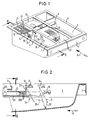
- the detergent drawer shown in Fig. 1 has three chambers open at the top, 1, 2 and 3. On its side, the drawer carries guide rails 4 and 5, by means of which the drawer is moved in guide grooves of a housing, not shown, in the pushing and pulling direction 6 can.
- the front bar 7 is used to mount a handle plate, not shown.
- the chamber 3 of the detergent drawer is equipped according to the prior art with a fixed bulkhead 8. It can only be used for powder detergents - here for prewash detergents.
- the chamber 2 is provided for liquid washing aids, preferably for fabric softeners.
- a known siphon system 9 is installed in the chamber, which has a non-visible stowage wall at the rear, which is not shown in detail here.
- the front chamber 1 is used to fill and store a dose of a main detergent, which can be in powder or liquid form.
- a main detergent which can be in powder or liquid form.
- the side chamber walls are stabilized by a bridge 11. Below that are attached to the chamber walls extending to the front guide rails 12. Together with other, but not visible in Fig. 1 slide guide strips, these strips 12 hold a frame-shaped slide 13 which carries the bulkhead wall 14 at its front end.
- the bulkhead wall 14 has a handle 15 on its front surface.
- the bulkhead wall is shown in Fig. 1 in the rear raised position of the drawer slide and is set in this position for use with a large portion of washing powder.
- This is indicated by the side wall marking, which contains an arrow 16 and a stylized representation 17 for a large portion of washing powder.
- the markings 18 are provided for the front raised position of the drawer guide for using the chamber with a small detergent dose and 19 for the front lowered position for using the chamber for a liquid detergent dose.
- the slide 20 is shown in its three positions provided in this exemplary embodiment.
- the rear raised position for adaptation to washing powder use with large doses is shown by the single-dot dashed representation.
- the lateral guide element 201 is - as will be explained further below - a pot which is open to the side and whose circular shape forms a swivel joint for the lowering in the front position.
- the frame 20 of the slide 13 is supported on the one hand on the lower slide guide bar 21; because of its overweight to the front, the frame is held upwards at the rear end by the pot 201 on the upper slide guide bar 12.
- the bulkhead wall 14 can thereby be transferred from the front raised position according to arrow 22 into the front lowered, triple-dashed position and can be held in this new position in that lateral locking grooves on the frame 20 of the slide 13 align with the lower thrust guide -Lock bar 21.
- the side strips 202 on the chamber wall between the guide strips 12 and 21 serve to lock the pot 201, which pulls on the slide 13 to the front bumps against the end faces of the strips 202. These end faces lie on a cylindrical surface which corresponds to the outer surface of the pot 201. As will be explained further below, the pot 201 can be lifted over the strips 202 so that the slide 13 can be completely removed from the chamber. This makes it easy to clean both the slide and the chamber.
- FIG. 3 clearly shows that the upper guide bar 12 and the lower guide bar 21 guide the frame in the vertical direction.
- the frame 20 is guided through the strips 202 in the horizontal direction.
- the strips 202 on the right in FIG. 3 are continued on the rear part of the chamber, so that the pouring boundary wall 14 in the lowered position is not obstructed by the sloping side of the chamber wall on the right.
- the slide 13 is shown enlarged compared to the previous representations in FIGS. 4 and 5. Its frame 20 is stabilized by means of rib-shaped reinforcements 203 on the side of the bulkhead delimitation wall 14 and carries one of the pots 201 on the outside at the rear ends of the side rails 204.
- such a pot 201 is hollow on the inside and has two parallel ribs 205 which retract obliquely backwards.
- the pot strikes with its cylinder part 206 against the end faces of the strips 202 (FIG. 2) when the slide 13 is pulled and prevents the slide from falling out of the slide guide 12, 21, but when the slide 13 is reinserted, these oblique ribs 205 slide from the inside onto the strips 202 and briefly force the ends of the frame bars 204 together until the pots 201 have been pushed past the strips and fall back into their original guide position between the guide strips 12 and 21.
- the latching bar 206 which is attached to the outside of the spars 204, slides along the entire guide path with its latching lugs 207 under the upper guide bar 12.
- the latching lugs 207 stop the movement of the slide 13 by abutment on the rear lower edge of a further bridge 211 between the chamber walls, which is part of the guide strips 12, so that this respective position is defined in a tangible manner.
- the slide 13 can be pushed into the front lowered position.
- a force must be overcome, which is given by the chamfered section 208 of the lower edge of each spar on the lower guide bar 21.
- the spars 204 in this section 208 must withdraw from the lower guide strips 21 until they fall into the locking grooves 209 which are provided obliquely in the spars 204.
- the frame 20 is rotatably guided on the end faces of the strips 202 by means of the pots 201. In the lower, lowered position, the frame is finally held in the locking grooves 209 by the guide strips 21.
- the latching groove also has a chamfer on its lower edge, via which the guide bar 21 can be lifted out of the latching groove again and guided under this spar via the outside of the spar 204.
- the frame 20 of the slide 13 has finger loops 210 on the inner sides of the ends of the frame bars 204, which are pressed together with the thumb and forefinger in the forward, raised position of the slide 13 can.
- the spars 204 bend elastically inwards and pull the pots 201 out of their guiding position between the guide strips 12 and 21. Then the slide 13 can be pulled off to the front, the pots 201 being raised above the stop on the end faces of the strips 202 and slide over these ledges.
Abstract
Description
Die Erfindung betrifft eine Waschmittel-Einspüleinrichtung für eine Haushaltwaschmaschine mit einer Kammer, die mittels beweglicher Teile für die Benutzung von Waschpulver oder Flüssigwaschmittel anpaßbar ist.The invention relates to a detergent dispenser for a household washing machine with a chamber which can be adapted by means of moving parts for the use of washing powder or liquid detergent.
Eine derartige Waschmittel-Einspüleinrichtung ist aus der DE 36 08 619 C2 bekannt. Darin ist eine Schüttbegrenzungswand als bewegliches Teil in wenigstens zwei im wesentlichen vertikal orientierten Gleitführungen an den beiden Seitenwänden der Kammer geführt, so daß sie sich bis auf den Boden der Kammer schieben läßt. In einer angehobenen Position ist diese Schüttbegrenzungswand an Waschpulver-Benutzung und in einer abgesenkten Position an Benutzung von flüssigen Waschhilfsmitteln angepaßt. Zur Anpassung der damit ausgestatteten Waschmittel-Kammer an kleinere Portionen von Waschpulver oder flüssigen Waschhilfsmitteln muß diese Schüttbegrenzungswand aus der einen Gleitführung in eine andere Gleitführung umgesteckt werden. Dabei wird sie aus der Waschmittel-Schublade zunächst vollständig entfernt. Wird die Bedienungsperson während dieses Vorgangs abgerufen, dann kann diese inzwischen von der Waschmittel-Schublade entfernte Schüttbegrenzungswand verloren gehen.Such a detergent dispenser is known from DE 36 08 619 C2. In it, a bulk boundary wall is guided as a movable part in at least two substantially vertically oriented sliding guides on the two side walls of the chamber, so that it can be pushed to the bottom of the chamber. In a raised position this bulkhead is adapted to the use of washing powder and in a lowered position to the use of liquid washing aids. In order to adapt the detergent chamber equipped with it to smaller portions of washing powder or liquid washing aids, this bulk boundary wall must be repositioned from one sliding guide into another sliding guide. It is first completely removed from the detergent drawer. If the operator is called up during this process, the bulkhead wall that has been removed from the detergent drawer can be lost.
Außerdem ist die Handhabung einer solchen Schüttbegrenzungswand beim Einführen in die Gleitführungen unhandlich; die jeweilige Gleitführung kann beim Einstecken verfehlt werden, so daß die Schüttbegrenzungswand eine unsichere Position einnimmt und - falls dies nicht erkannt wurde - beim nächsten Einspülvorgang nach hinten aus der Waschmittel-Schublade ausgespült werden. Im ungünstigsten Fall kann die Schüttbegrenzungswand zusammen mit dem Waschmittel in den Laugenbehälter der Waschmaschine eingespült werden. Beim Verhaken dieser Schüttbegrenzungswand innerhalb des Laugenbehälters, z.B. am Heizkörper können sogar Schäden am Heizkörper, an seinen Befestigungsteilen oder am Temperaturgeber entstehen.In addition, the handling of such a bulkhead wall is cumbersome when inserted into the slide guides; the respective slide guide can be missed when it is inserted, so that the bulkhead wall occupies an unsafe position and - if this was not recognized - can be rinsed out of the detergent drawer to the rear during the next rinsing process. In the worst case, the bulkhead wall can be flushed into the washing machine's tub with the detergent. If this bulkhead wall gets caught inside the tub, e.g. the radiator can even damage the radiator, its fasteners or the temperature sensor.
Der Erfindung liegt die Aufgabe zugrunde, eine Waschmittel-Einspüleinrichtung der oben genannten Art mit einer beweglichen Schüttbegrenzungswand auszubilden, die weder verloren gehen kann, noch als loses Teil in den Laugenbehälter der Waschmaschine gelangen kann und die leichter handhabbar ist ohne die Gefahr einer unsicheren Positionierung.The invention has for its object to provide a detergent dispenser of the type mentioned above with a movable bulkhead wall which can neither be lost nor get into the washing machine's tub as a loose part and which is easier to handle without the risk of unsafe positioning.
Diese Aufgabe wird erfindungsgemäß dadurch gelöst, daß das bewegliche Teil eine an einer im wesentlichen quer zu seiner Hauptausdehnung orientierten Schubführung gehaltene Schüttbegrenzungswand ist, die zur Anpassung an Waschpulver-Benutzung in einer hinteren angehobenen Position der Schubführung und zur Anpassung an Benutzung von Flüssigwaschmitteln in einer vorderen abgesenkten Position einstellbar ist.This object is achieved in that the movable part is a bulkhead wall held on a thrust guide oriented essentially transversely to its main extent, which wall is adapted to adapt to the use of washing powder a rear raised position of the drawer guide and for adaptation to the use of liquid detergents is adjustable in a front lowered position.
Durch die neuartige Schubführung der Schüttbegrenzungswand kann diese, wenn gewünscht, an beliebig vielen Positionen der Schubführung rastbar positioniert werden und in mindestens einer vorderen abgesenkten Position sogar als Schüttbegrenzungswand für die Benutzung von Flüssigwaschmitteln dienen. Die erfindungsgemäße Schüttbegrenzungswand muß zwecks Anpassung nicht mehr aus der Kammer entnommen werden, sondern wird nur innerhalb der Kammer in einer Schubführung bewegt und gegebenenfalls abgesenkt bzw. aus der abgesenkten Position wieder angehoben. Die mit der Entnahme der bekannten Schüttbegrenzungswand verbundenen Nachteile sind daher vermieden.Due to the new thrust guide of the bulkhead wall, if desired, it can be positioned in any number of positions of the drawer guide and even serve as a bulkhead wall for the use of liquid detergents in at least one front lowered position. The pouring restriction wall according to the invention no longer has to be removed from the chamber for the purpose of adaptation, but is only moved in a slide guide within the chamber and, if necessary, lowered or raised again from the lowered position. The disadvantages associated with the removal of the known bulkhead wall are therefore avoided.
In einer vorteilhaften Ausführungsform der Erfindung weist die Schüttbegrenzungswand auf der Führungsstrecke zwischen der hinteren angehobenen Position und der vorderen abgesenkten Position zur Anpassung des Kammer-Volumens an unterschiedliche geforderte Waschpulver-Mengen in angehobener Position mindestens eine zusätzliche Raststellung auf.In an advantageous embodiment of the invention, the bulk boundary wall has at least one additional latching position on the guide path between the rear raised position and the front lowered position for adapting the chamber volume to different required amounts of washing powder in the raised position.
In einer weiteren vorteilhaften Ausführungsform der Erfindung ist die Schüttbegrenzungswand an einem Schieber mit seitlichen Führungselementen angebracht, die auf der Strecke zwischen der hinteren und der vorderen Position in Gegenführungselementen gleitgeführt und in der vorderen Position zum Absenken der Schüttbegrenzungswand drehgeführt sind. Mit den Erweiterungsmerkmalen ist die erfindungsgemäße Schüttbegrenzungswand zusätzlich aus der Kammer entnehmbar, damit beide Teile unabhängig voneinander gereinigt werden können. Hierzu muß aber die Waschmittel-Einspülschale aus ihrem Gehäuse entnommen werden.In a further advantageous embodiment of the invention, the bulk boundary wall is attached to a slide with lateral guide elements which are slidably guided in the opposite guide elements on the distance between the rear and the front position and are rotationally guided in the front position for lowering the bulk barrier wall. With the expansion features, the bulkhead wall according to the invention can also be removed from the chamber so that both parts can be cleaned independently of one another. To do this, the detergent dispenser tray must be removed from its housing.
Anhand eines in der Zeichnung dargestellten Ausführungsbeispiels ist die Erfindung nachstehend erläutert. Es zeigen
- Fig. 1
- eine erfindungsgemäß ausgestattete Waschmittel-Schublade in perspektivischer Ansicht von oben,
- Fig. 2
- einen Längsschnitt durch die vordere erfindungsgemäß gestaltete Waschmittel-Kammer entlang der Schnittlinie II-II in Fig. 1,
- Fig. 3
- einen Querschnitt durch die erfindungsgemäß gestaltete Kammer entlang der Schnittlinie III-III in Fig. 2,
- Fig. 4
- einen Schieber mit Schüttbegrenzungswand in Seitenansicht und
- Fig. 5
- einen Schieber gemäß Fig. 4 in Draufsicht.
- Fig. 1
- an inventive detergent drawer in a perspective view from above,
- Fig. 2
- 2 shows a longitudinal section through the front detergent chamber designed according to the invention along the section line II-II in FIG. 1,
- Fig. 3
- 3 shows a cross section through the chamber designed according to the invention along the section line III-III in FIG. 2,
- Fig. 4
- a slide with bulkhead wall in side view
- Fig. 5
- a slide according to FIG. 4 in plan view.
Die in Fig. 1 dargestellte Waschmittel-Schublade hat drei oben offene Kammern, 1, 2 und 3. An ihrer Seite trägt die Schublade Führungsleisten 4 und 5, mittels derer die Schublade in Führungsnuten eines nicht dargestellten Gehäuses in Schub- und Zugrichtung 6 bewegt werden kann. Die vordere Leiste 7 dient zur Montage einer nicht dargestellten Griffplatte.The detergent drawer shown in Fig. 1 has three chambers open at the top, 1, 2 and 3. On its side, the drawer carries
Die Kammer 3 der Waschmittel-Schublade ist gemäß dem Stand der Technik mit einer festen Schüttbegrenzungswand 8 ausgestattet. Sie ist nur für pulverförmige Waschmittel - hier für Vorwaschmittel - verwendbar.The chamber 3 of the detergent drawer is equipped according to the prior art with a
Die Kammer 2 ist für flüssige Waschhilfsmittel vorgesehen, vorzugsweise für Weichspülmittel. Dazu ist in der Kammer, die hinten eine nicht sichtbare feste Stauwand besitzt, ein bekanntes Saughebersystem 9 eingebaut, das hier im einzelnen nicht näher dargestellt ist. Es trägt an seiner vorderen Partie 10 eine Merkeinrichtung für eine eingestellte, aktuelle Wasserhärte.The chamber 2 is provided for liquid washing aids, preferably for fabric softeners. For this purpose, a known
Die vordere Kammer 1 dient zum Befüllen und Bevorraten einer Dosis eines Haupt-Waschmittels, das in pulverförmiger oder in flüssiger Form vorliegen kann. An ihrem hinteren Ende werden die seitlichen Kammerwände durch eine Brücke 11 stabilisiert. Darunter sind an den Kammerwänden nach vorn sich erstreckende Schubführungsleisten 12 angebracht. Zusammen mit weiteren, in Fig. 1 aber nicht sichtbaren Schubführungsleisten halten diese Leisten 12 einen rahmenförmigen Schieber 13, der an seinem vorderen Ende die Schüttbegrenzungswand 14 trägt.The
Die Schüttbegrenzungswand 14 hat an ihrer Vorderfläche eine Griffhilfe 15. Die Schüttbegrenzungswand ist in Fig. 1 in der hinteren angehobenen Position der Schubführung dargestellt und in dieser Position zur Benutzung mit einer großen Waschpulver-Portion eingestellt. Dies ist durch die seitliche Wandmarkierung angezeigt, die einen Pfeil 16 und eine stilisierte Darstellung 17 für eine große Waschpulver-Portion enthält. Entsprechend sind die Markierungen 18 für die vordere angehobene Position der Schubführung zur Benutzung der Kammer mit einer kleinen Waschpulver-Dosis und 19 für die vordere abgesenkte Position zur Benutzung der Kammer für eine Flüssigwaschmittel-Dosis vorgesehen.The
In der Schnittdarstellung gemäß Fig. 2 ist der Schieber 20 in seinen drei, in diesem Ausführungsbeispiel vorgesehenen Positionen dargestellt. Die hintere angehobene Position zur Anpassung an Waschpulver-Benutzung mit großer Dosierung ist durch die einfachpunktstrichlierte Darstellung gezeigt. Darin ist eine seitliches Führungselement 201 in der hinteren Position dargestellt, das den Rahmen des Schiebers 13 auf der unteren Schubführungsleiste 21 abstützt. Das seitliche Führungselement 201 ist - wie weiter unten noch ausgeführt ist - ein zur Seite hin offener Topf, dessen kreisrunde Form für die Absenkung in der vorderen Position ein Drehgelenk bildet.In the sectional view according to FIG. 2, the
In der vorderen angehoben, doppeltpunktstrichlierten Position, bei der die Schüttbegrenzungswand an eine Waschpulver-Benutzung mit kleiner Dosismenge (18) angepaßt ist, wird der Rahmen 20 des Schiebers 13 einerseits auf der unteren Schubführungs-Leiste 21 abgestützt; wegen seines Übergewichts nach vorn wird der Rahmen aber an seinem hinteren Ende vom Topf 201 nach oben an der oberen Schubführungs-Leiste 12 gehalten.In the front raised, double-dashed position, in which the bulkhead wall is adapted to a washing powder use with a small dose amount (18), the
Wie weiter unten noch erläutert wird, kann die Schüttbegrenzungswand 14 aus der vorderen angehobenen Position gemäß Pfeil 22 dadurch in die vordere abgesenkte, dreifachpunktstrichlierte Position überführt und in dieser neuen Position gehalten werden, daß seitliche Rastnuten am Rahmen 20 des Schiebers 13 sich mit der unteren Schubführungs-Leiste 21 verrasten.As will be explained further below, the
Die seitlichen Leisten 202 an der Kammerwandung zwischen den Führungsleisten 12 und 21 dienen zur Arretierung des Topfes 201, der bei Zug am Schieber 13 nach vorn gegen die Stirnseiten der Leisten 202 stößt. Diese Stirnseiten liegen auf einer Zylinderfläche, die mit der Mantelfläche des Topfes 201 korrespondiert. Wie weiter unten noch ausgeführt ist, kann der Topf 201 über die Leisten 202 hinweggehoben werden, damit der Schieber 13 aus der Kammer vollständig entnommen werden kann. Hierdurch sind sowohl der Schieber wie auch die Kammer einfach zu reinigen.The
Der Querschnitt in Fig. 3 zeigt deutlich, daß die obere Führungsleiste 12 und die untere Führungsleiste 21 den Rahmen in vertikaler Richtung führen. In horizontaler Richtung wird der Rahmen 20 durch die Leisten 202 geführt. Dabei sind die in Fig. 3 rechten Leisten 202 im Gegensatz zu den linken Leisten an der hinten Partie der Kammer abstandschaffend weitergeführt, damit die Schüttbegrenzungswand 14 in der abgesenkten Position nicht von der rechtsseitigen Schräge der Kammerwandung behindert wird.The cross section in Fig. 3 clearly shows that the
Der Schieber 13 ist gegenüber den vorherigen Darstellungen in Fig. 4 und 5 vergrößert dargestellt. Sein Rahmen 20 ist mittels rippenförmiger Versteifungen 203 auf der Seite der Schüttbegrenzungswand 14 stabilisiert und trägt an den hinteren Enden der Seitenholme 204 außen seitlich je einen der Töpfe 201.The
Gemäß der Schnittdarstellung entlang der Schnittlinie V-V ist ein solcher Topf 201 innen hohl und hat zwei parallele Rippen 205, die nach hinten schräg zurückweichen. Dadurch schlägt zwar der Topf beim Ziehen am Schieber 13 mit seinem Zylinderteil 206 gegen die Stirnseiten der Leisten 202 (Fig. 2) und bewahrt den Schieber vor einem Herausfallen aus der Schubführung 12, 21, aber beim Wiedereinsetzen des Schiebers 13 gleiten diese schrägen Rippen 205 von innen auf die Leisten 202 auf und zwängen die Enden der Rahmenholme 204 kurzzeitig zusammen, bis die Töpfe 201 an den Leisten vorbeigeschoben worden sind und wieder in ihre ursprüngliche Führungshaltung zwischen den Führungsleisten 12 und 21 zurückfallen. Auf dem gesamten Führungsweg gleitet die außen an den Holmen 204 angebrachte Rastleiste 206 mit ihren Rastnasen 207 unter der oberen Führungsleiste 12 entlang. In den vorgesehenen vorderen und hinteren Positionen stoppen die Rastnasen 207 die Bewegung des Schiebers 13 durch Anschlag an der hinteren Unterkante einer weiteren Brücke 211 zwischen den Kammerwänden, die Bestandteil der Führungsleisten 12 ist, damit diese jeweilige Position fühlbar definiert ist.According to the sectional view along the section line V-V, such a
Aus der vorderen angehobenen Position kann der Schieber 13 in die vordere abgesenkte Position gedrückt werden. Dazu muß eine Kraft überwunden werden, die durch die Auflage des gefasten Abschnitts 208 der Unterkante jedes Holms auf der unteren Führungsleiste 21 gegeben ist. Zur Überwindung dieser Kraft müssen die Holme 204 in diesem Abschnitt 208 von den unteren Führungsleisten 21 zurückweichen, bis diese in die schräg in den Holmen 204 angebrachten Rastnuten 209 fallen. Während dieser Bewegung wird der Rahmen 20 mittels der Töpfe 201 an den Stirnseiten der Leisten 202 drehgeführt. In der unteren abgesenkten Position wird der Rahmen schließlich durch die Führungsleisten 21 in den Rastnuten 209 gehalten.From the front raised position, the
Zur Erleichterung der Anhebung des Schiebers 13 aus dieser abgesenkten Position besitzt die Rastnut an ihrer Unterkante ebenfalls eine Fase, über die die Führungsleiste 21 wieder aus der Rastnut gehoben und über die Außenseite des Holms 204 unter diesen Holm geführt werden kann.To facilitate the lifting of the
Zur Entnahme aus der Kammer hat der Rahmen 20 des Schiebers 13 an den Innenseiten der Enden der Rahmenholme 204 Fingerösen 210, die in vorderer angehobener Position des Schiebers 13 mit Daumen und Zeigefinger zusammengedrückt werden können. Dabei biegen sich die Holme 204 elastisch nach innen und ziehen die Töpfe 201 aus ihrer Führungshaltung zwischen den Führungsleisten 12 und 21. Dann kann der Schieber 13 nach vorn abgezogen werden, wobei die Töpfe 201 über den oben erwähnten Anschlag an den Stirnseiten der Leisten 202 gehoben werden und über diese Leisten hinweggleiten.For removal from the chamber, the
Claims (3)
Applications Claiming Priority (2)
| Application Number | Priority Date | Filing Date | Title |
|---|---|---|---|
| DE19505734A DE19505734A1 (en) | 1995-02-20 | 1995-02-20 | Detergent dispenser for a household washing machine |
| DE19505734 | 1995-02-20 |
Publications (3)
| Publication Number | Publication Date |
|---|---|
| EP0727520A2 true EP0727520A2 (en) | 1996-08-21 |
| EP0727520A3 EP0727520A3 (en) | 1996-12-27 |
| EP0727520B1 EP0727520B1 (en) | 1999-09-08 |
Family
ID=7754477
Family Applications (1)
| Application Number | Title | Priority Date | Filing Date |
|---|---|---|---|
| EP96101927A Expired - Lifetime EP0727520B1 (en) | 1995-02-20 | 1996-02-09 | Washing product dispenser for a household washing machine |
Country Status (3)
| Country | Link |
|---|---|
| EP (1) | EP0727520B1 (en) |
| DE (2) | DE19505734A1 (en) |
| ES (1) | ES2138251T3 (en) |
Cited By (6)
| Publication number | Priority date | Publication date | Assignee | Title |
|---|---|---|---|---|
| WO2005116322A1 (en) * | 2004-04-14 | 2005-12-08 | Lg Electronics Inc. | Detergent container of washing machine |
| EP1607508A2 (en) * | 2004-06-14 | 2005-12-21 | Samsung Electronics Co., Ltd. | Washing machine with detergent supply unit |
| EP1764437A1 (en) * | 2005-09-16 | 2007-03-21 | Whirlpool Corporation | Detergent dispenser for a clothes washing machine |
| CN102575410A (en) * | 2009-08-12 | 2012-07-11 | 伊莱克斯家用产品股份有限公司 | Home appliance having detergent compartment |
| EP2889419A1 (en) * | 2013-12-24 | 2015-07-01 | Electrolux Appliances Aktiebolag | Laundry washing machine |
| CN106460295A (en) * | 2014-06-23 | 2017-02-22 | Lg电子株式会社 | Detergent feeding device for washer |
Families Citing this family (4)
| Publication number | Priority date | Publication date | Assignee | Title |
|---|---|---|---|---|
| KR101013374B1 (en) * | 2003-11-10 | 2011-02-14 | 삼성전자주식회사 | Washing machine having detergent feeding device |
| EP2003237B1 (en) | 2007-06-12 | 2016-05-04 | Electrolux Home Products Corporation N.V. | Laundry washing machine dispenser for detergent products |
| DK2460925T3 (en) | 2010-12-01 | 2014-02-24 | Primus Ce S R O | Detergent dispenser |
| CN102444005B (en) * | 2011-09-23 | 2013-09-04 | 南京乐金熊猫电器有限公司 | Device and method for preventing liquid detergents from being fed by mistake |
Citations (2)
| Publication number | Priority date | Publication date | Assignee | Title |
|---|---|---|---|---|
| DE3608619A1 (en) * | 1986-03-14 | 1987-09-17 | Bosch Siemens Hausgeraete | WASHING MACHINE WITH A DETERGENT DISH WASHER |
| DE4325821A1 (en) * | 1993-07-31 | 1995-02-02 | Foron Waschgeraete Gmbh | Device for flushing water and/or care agents into washing machines or dishwashers |
-
1995
- 1995-02-20 DE DE19505734A patent/DE19505734A1/en not_active Withdrawn
-
1996
- 1996-02-09 EP EP96101927A patent/EP0727520B1/en not_active Expired - Lifetime
- 1996-02-09 ES ES96101927T patent/ES2138251T3/en not_active Expired - Lifetime
- 1996-02-09 DE DE59602978T patent/DE59602978D1/en not_active Expired - Fee Related
Patent Citations (2)
| Publication number | Priority date | Publication date | Assignee | Title |
|---|---|---|---|---|
| DE3608619A1 (en) * | 1986-03-14 | 1987-09-17 | Bosch Siemens Hausgeraete | WASHING MACHINE WITH A DETERGENT DISH WASHER |
| DE4325821A1 (en) * | 1993-07-31 | 1995-02-02 | Foron Waschgeraete Gmbh | Device for flushing water and/or care agents into washing machines or dishwashers |
Cited By (13)
| Publication number | Priority date | Publication date | Assignee | Title |
|---|---|---|---|---|
| WO2005116322A1 (en) * | 2004-04-14 | 2005-12-08 | Lg Electronics Inc. | Detergent container of washing machine |
| US7428831B2 (en) | 2004-04-14 | 2008-09-30 | Lg Electronics Inc. | Detergent container of washing machine |
| EP1607508A2 (en) * | 2004-06-14 | 2005-12-21 | Samsung Electronics Co., Ltd. | Washing machine with detergent supply unit |
| EP1607508A3 (en) * | 2004-06-14 | 2007-06-27 | Samsung Electronics Co., Ltd. | Washing machine with detergent supply unit |
| EP1764437A1 (en) * | 2005-09-16 | 2007-03-21 | Whirlpool Corporation | Detergent dispenser for a clothes washing machine |
| CN102575410B (en) * | 2009-08-12 | 2015-06-17 | 伊莱克斯家用产品股份有限公司 | Home appliance having detergent compartment |
| CN102575410A (en) * | 2009-08-12 | 2012-07-11 | 伊莱克斯家用产品股份有限公司 | Home appliance having detergent compartment |
| EP2889419A1 (en) * | 2013-12-24 | 2015-07-01 | Electrolux Appliances Aktiebolag | Laundry washing machine |
| WO2015096988A1 (en) * | 2013-12-24 | 2015-07-02 | Electrolux Appliances Aktiebolag | Laundry washing machine |
| CN106460295A (en) * | 2014-06-23 | 2017-02-22 | Lg电子株式会社 | Detergent feeding device for washer |
| EP3158123A4 (en) * | 2014-06-23 | 2017-11-22 | LG Electronics Inc. | Detergent feeding device for washer |
| CN106460295B (en) * | 2014-06-23 | 2019-01-22 | Lg电子株式会社 | The detergent delivery device of washing machine |
| US10508381B2 (en) | 2014-06-23 | 2019-12-17 | Lg Electronics Inc. | Detergent feeding device for washer |
Also Published As
| Publication number | Publication date |
|---|---|
| ES2138251T3 (en) | 2000-01-01 |
| DE59602978D1 (en) | 1999-10-14 |
| EP0727520B1 (en) | 1999-09-08 |
| DE19505734A1 (en) | 1996-08-22 |
| EP0727520A3 (en) | 1996-12-27 |
Similar Documents
| Publication | Publication Date | Title |
|---|---|---|
| EP0727520B1 (en) | Washing product dispenser for a household washing machine | |
| DE1810636A1 (en) | Automatic dishwasher | |
| DE1778350B2 (en) | Plastic injection molding machine with a mold clamping unit that accommodates an injection mold | |
| DE2639923C2 (en) | Detergent dispenser | |
| DE4005348A1 (en) | COFFEE MACHINE | |
| DE1237744B (en) | Dish carrier for a dishwasher | |
| DE4133667C2 (en) | Device for cleaning the wheels of two-wheeled carts, in particular caddy cars | |
| CH647983A5 (en) | STORAGE CABINET. | |
| DE60302213T2 (en) | Dish rack for dishwashers | |
| DE3607632C2 (en) | ||
| DE2044365A1 (en) | Cupboard, especially office cupboard for hanging files | |
| DE3414474A1 (en) | CHEESE PRESS | |
| EP3598924B1 (en) | Support, insert and dispensing device for unpacked goods | |
| DE2856880C2 (en) | Thermoplastic battery tank | |
| DE3430872C2 (en) | Device for injection molding molded parts | |
| DE2209532A1 (en) | BAR FOR INSERTING CURTAIN BRACKETS | |
| DE3511053A1 (en) | STACKABLE STORAGE GOODS AND THE CRANE REVERSE THAT MATCHES | |
| DE10117546A1 (en) | Folding laundry drying stand has frame with first transverse spars and two additional second spars | |
| DE4317138C2 (en) | Arrangement for the storage of sterile goods containers or the like | |
| DE2941578C2 (en) | Dosing device for liquids | |
| DE3002408A1 (en) | DEVICE FOR SECURING DRAWERS IN DRAWER CABINETS | |
| DE2328604C3 (en) | Delivery frame for emptying brewing powder packaging in portions | |
| DE2508036B2 (en) | Locking device for drawers arranged one above the other in a housing or frame | |
| DE187435C (en) | ||
| DE3129366C2 (en) | Device for locking two column parts of a transport plate that can be brought one above the other on the same axis |
Legal Events
| Date | Code | Title | Description |
|---|---|---|---|
| PUAI | Public reference made under article 153(3) epc to a published international application that has entered the european phase |
Free format text: ORIGINAL CODE: 0009012 |
|
| AK | Designated contracting states |
Kind code of ref document: A2 Designated state(s): DE ES FR GB IT |
|
| PUAL | Search report despatched |
Free format text: ORIGINAL CODE: 0009013 |
|
| AK | Designated contracting states |
Kind code of ref document: A3 Designated state(s): DE ES FR GB IT |
|
| 17P | Request for examination filed |
Effective date: 19970617 |
|
| RAP1 | Party data changed (applicant data changed or rights of an application transferred) |
Owner name: BSH BOSCH UND SIEMENS HAUSGERAETE GMBH |
|
| GRAG | Despatch of communication of intention to grant |
Free format text: ORIGINAL CODE: EPIDOS AGRA |
|
| GRAG | Despatch of communication of intention to grant |
Free format text: ORIGINAL CODE: EPIDOS AGRA |
|
| GRAH | Despatch of communication of intention to grant a patent |
Free format text: ORIGINAL CODE: EPIDOS IGRA |
|
| 17Q | First examination report despatched |
Effective date: 19990226 |
|
| GRAH | Despatch of communication of intention to grant a patent |
Free format text: ORIGINAL CODE: EPIDOS IGRA |
|
| GRAA | (expected) grant |
Free format text: ORIGINAL CODE: 0009210 |
|
| AK | Designated contracting states |
Kind code of ref document: B1 Designated state(s): DE ES FR GB IT |
|
| ET | Fr: translation filed | ||
| GBT | Gb: translation of ep patent filed (gb section 77(6)(a)/1977) |
Effective date: 19990910 |
|
| REF | Corresponds to: |
Ref document number: 59602978 Country of ref document: DE Date of ref document: 19991014 |
|
| ITF | It: translation for a ep patent filed |
Owner name: STUDIO JAUMANN P. & C. S.N.C. |
|
| REG | Reference to a national code |
Ref country code: ES Ref legal event code: FG2A Ref document number: 2138251 Country of ref document: ES Kind code of ref document: T3 |
|
| PLBE | No opposition filed within time limit |
Free format text: ORIGINAL CODE: 0009261 |
|
| STAA | Information on the status of an ep patent application or granted ep patent |
Free format text: STATUS: NO OPPOSITION FILED WITHIN TIME LIMIT |
|
| 26N | No opposition filed | ||
| REG | Reference to a national code |
Ref country code: GB Ref legal event code: IF02 |
|
| PGFP | Annual fee paid to national office [announced via postgrant information from national office to epo] |
Ref country code: GB Payment date: 20030127 Year of fee payment: 8 |
|
| PGFP | Annual fee paid to national office [announced via postgrant information from national office to epo] |
Ref country code: ES Payment date: 20030206 Year of fee payment: 8 |
|
| PGFP | Annual fee paid to national office [announced via postgrant information from national office to epo] |
Ref country code: FR Payment date: 20030221 Year of fee payment: 8 |
|
| PG25 | Lapsed in a contracting state [announced via postgrant information from national office to epo] |
Ref country code: GB Free format text: LAPSE BECAUSE OF NON-PAYMENT OF DUE FEES Effective date: 20040209 |
|
| PG25 | Lapsed in a contracting state [announced via postgrant information from national office to epo] |
Ref country code: ES Free format text: LAPSE BECAUSE OF NON-PAYMENT OF DUE FEES Effective date: 20040210 |
|
| GBPC | Gb: european patent ceased through non-payment of renewal fee |
Effective date: 20040209 |
|
| PG25 | Lapsed in a contracting state [announced via postgrant information from national office to epo] |
Ref country code: FR Free format text: LAPSE BECAUSE OF NON-PAYMENT OF DUE FEES Effective date: 20041029 |
|
| REG | Reference to a national code |
Ref country code: FR Ref legal event code: ST |
|
| PG25 | Lapsed in a contracting state [announced via postgrant information from national office to epo] |
Ref country code: IT Free format text: LAPSE BECAUSE OF NON-PAYMENT OF DUE FEES;WARNING: LAPSES OF ITALIAN PATENTS WITH EFFECTIVE DATE BEFORE 2007 MAY HAVE OCCURRED AT ANY TIME BEFORE 2007. THE CORRECT EFFECTIVE DATE MAY BE DIFFERENT FROM THE ONE RECORDED. Effective date: 20050209 |
|
| REG | Reference to a national code |
Ref country code: ES Ref legal event code: FD2A Effective date: 20040210 |
|
| PGFP | Annual fee paid to national office [announced via postgrant information from national office to epo] |
Ref country code: DE Payment date: 20090228 Year of fee payment: 14 |
|
| PG25 | Lapsed in a contracting state [announced via postgrant information from national office to epo] |
Ref country code: DE Free format text: LAPSE BECAUSE OF NON-PAYMENT OF DUE FEES Effective date: 20100901 |