EP0727361A2 - Snap-hinged cap - Google Patents
Snap-hinged cap Download PDFInfo
- Publication number
- EP0727361A2 EP0727361A2 EP96301048A EP96301048A EP0727361A2 EP 0727361 A2 EP0727361 A2 EP 0727361A2 EP 96301048 A EP96301048 A EP 96301048A EP 96301048 A EP96301048 A EP 96301048A EP 0727361 A2 EP0727361 A2 EP 0727361A2
- Authority
- EP
- European Patent Office
- Prior art keywords
- cap
- section
- straps
- main body
- body section
- Prior art date
- Legal status (The legal status is an assumption and is not a legal conclusion. Google has not performed a legal analysis and makes no representation as to the accuracy of the status listed.)
- Granted
Links
- 230000002093 peripheral effect Effects 0.000 claims abstract description 93
- 229920003002 synthetic resin Polymers 0.000 claims abstract description 5
- 239000000057 synthetic resin Substances 0.000 claims abstract description 5
- 229920001169 thermoplastic Polymers 0.000 claims abstract description 4
- 239000004416 thermosoftening plastic Substances 0.000 claims abstract description 4
- 239000010408 film Substances 0.000 description 27
- 230000000694 effects Effects 0.000 description 8
- 239000007788 liquid Substances 0.000 description 7
- 238000010276 construction Methods 0.000 description 5
- 230000005489 elastic deformation Effects 0.000 description 4
- 238000004806 packaging method and process Methods 0.000 description 3
- 239000002344 surface layer Substances 0.000 description 2
- 239000004698 Polyethylene Substances 0.000 description 1
- 230000002411 adverse Effects 0.000 description 1
- 230000015556 catabolic process Effects 0.000 description 1
- 239000012141 concentrate Substances 0.000 description 1
- 238000006731 degradation reaction Methods 0.000 description 1
- 230000000994 depressogenic effect Effects 0.000 description 1
- 238000007599 discharging Methods 0.000 description 1
- -1 polyethylene Polymers 0.000 description 1
- 229920000573 polyethylene Polymers 0.000 description 1
- 229920005992 thermoplastic resin Polymers 0.000 description 1
- 239000010409 thin film Substances 0.000 description 1
Images








Classifications
-
- B—PERFORMING OPERATIONS; TRANSPORTING
- B65—CONVEYING; PACKING; STORING; HANDLING THIN OR FILAMENTARY MATERIAL
- B65D—CONTAINERS FOR STORAGE OR TRANSPORT OF ARTICLES OR MATERIALS, e.g. BAGS, BARRELS, BOTTLES, BOXES, CANS, CARTONS, CRATES, DRUMS, JARS, TANKS, HOPPERS, FORWARDING CONTAINERS; ACCESSORIES, CLOSURES, OR FITTINGS THEREFOR; PACKAGING ELEMENTS; PACKAGES
- B65D47/00—Closures with filling and discharging, or with discharging, devices
- B65D47/04—Closures with discharging devices other than pumps
- B65D47/06—Closures with discharging devices other than pumps with pouring spouts or tubes; with discharge nozzles or passages
- B65D47/08—Closures with discharging devices other than pumps with pouring spouts or tubes; with discharge nozzles or passages having articulated or hinged closures
- B65D47/0804—Closures with discharging devices other than pumps with pouring spouts or tubes; with discharge nozzles or passages having articulated or hinged closures integrally formed with the base element provided with the spout or discharge passage
- B65D47/0809—Closures with discharging devices other than pumps with pouring spouts or tubes; with discharge nozzles or passages having articulated or hinged closures integrally formed with the base element provided with the spout or discharge passage and elastically biased towards both the open and the closed positions
- B65D47/0814—Closures with discharging devices other than pumps with pouring spouts or tubes; with discharge nozzles or passages having articulated or hinged closures integrally formed with the base element provided with the spout or discharge passage and elastically biased towards both the open and the closed positions by at least three hinge sections, at least one having a length different from the others
Definitions
- This invention relates to an improved to a snap-hinged cap to be mainly used to close and open a liquid discharge opening with a snap motion.
- a snap-hinged cap is to be used close and open a liquid discharge opening is already known from Japanese Patent Publication No. 3-53182.
- a snap-hinged cap disclosed in the above patent publication is provided with a film hinge A and a pair of straps B arranged along the respective lateral sides of and slightly below the film hinge.
- the film hinge and the straps mutually connect a main body section C and a cap D.
- the straps B are made substantially straight when the cap D is opened, although the straps B have a length shorter than the arc traced by the cap D when it is swung open or closed, and expanded to operate as springs when the straps are moving so that they are held under stress when the cap D is in an intermediary position between the closed position and the opened position.
- each of the points F connecting the respective straps B and the cap D traces an arc E as the cap D swings around the axis 0 of swinging motion of the film hinge A.
- the straps B swing around the respective points G connecting the straps and the main body section C so that the connection points F are supposed to trace respective arcs H as free ends.
- the distance E of expansion is a sum of an amount L1 of deformation of the strap B at the connecting points F and G where it is hooked and an amount L2 of expansion of the strap B that gives rise to the above spring effect.
- a snap-hinged cap comprising straps that are not subjected to strong external tensile force and hence not accompanied by the problem of losing their mechanical strength and producing exfoliated surface layers, if the cap is repeatedly opened and closed, so that the snap-hinged cap can maintain its snap effect without requiring the use of a complicated structure and that of synthetic resin by an increased amount and affecting adversely to capping, packaging and related operations.
- a snap-hinged cap comprising a main body section of thermoplastic synthetic resin, a cap integrally molded with the main body section, a film hinge connecting the main body section and the cap, and straps arranged on both lateral sides of the film hinge, wherein
- each of the straps connecting the main body section and the cap and arranged along the respective lateral sides of the film hinge has a center line longer than the straight line between the opposite ends thereof connected respectively to the main body section and the cap and the skirt section of the cap has a peripheral wall having a wall thickness reduced in portions located adjacent to the film hinge and the respective straps from the wall thickness in the remaining portion, the situation where the straps are made short and not sufficient to accommodate the swinging motion of the cap and the insufficiency in the length of the straps is compensated by elastic deformation of the straps and that of the thin areas of the skirt section to make the film hinge and the straps subjected to excessive external tensile force as in the case of conventional snap-hinged caps is effectively prevented and the straps shows elastic resiliency to give rise to a good snap effect.
- Each of the straps may have a compressed V-shaped lateral view and a bent section.
- the bent section is projected toward a center of the cap when the cap is closed, and the bent section is projected upwardly when the cap is opened. Since each of the straps shows a mildly V-shaped lateral view, it can be easily extended and elastically deformed to stretch itself into a straight form. Additionally, since the bent sections of the mildly V-shaped straps project toward the central axis of the cap when the cap is closed, the portions of the straps projecting outward from the outer peripheral surface of the snap-hinged cap can be dimensionally minimized.
- Each of the straps may have the largest thickness at the respective bent sections of compressed V-shape. Since the straps have the largest thickness at the respective bent sections of their mild V-shapes, they show a strong elastic resiliency when they are elastically deformed and stretched into an almost straight form.
- Said thin portion may include a transversal cross sectional view concaved toward a center of the cap. Since each of the portions of the skirt section of the cap formed outside the straps and having a reduced thickness comprises a peripheral wall section having a transversal cross sectional view concaved toward the center of the cap, those portions can be easily and elastically deformed to reduce any external tensile force to which the straps are subjected.
- Said skirt section of the cap may include a thin portion.
- the thin portion comprises an inner peripheral wall having a transversal cross sectional view convexed outwardly and formed on an inner peripheral wall of the skirt section, and an outer peripheral surface which is continuously and smoothly extending from an outer peripheral surface of the skirt section. Since each of the portions of the skirt section of the cap formed outside the straps and having a reduced thickness comprises a peripheral wall section having a transversal cross sectional view convexed toward the center of the cap and an outer peripheral surface continuously and smoothly extending from the outer peripheral surface of the remaining portion of the skirt section, the snap-hinged cap provides a good appearance and can adapt itself stably to bottling operation in a bottling line using a hopper to enhance the rate of bottling operation.
- the thin portion may include a thin peripheral wall section having a transversal cross sectional view concaved toward a center of the cap, and a notch provided opposite to the straps relating to the thin peripheral wall section. Since each of the portions of the skirt section of the cap formed outside the straps and having a reduced thickness makes the outer peripheral surface of the cap transversally longer to a certain extent than its counterpart of a snap-hinged cap according to claim 1 or claim 4, the snap-hinged cap can adapt itself more stably to bottling operation in a bottling line and the resiliency of the portions of the skirt section having a reduced thickness can be improved to some extent.
- the peripheral wall of the main body section may have a cylindrical shape
- the skirt section of the cap may have a cylindrical shape.
- the skirt section has thin peripheral wall sections. Connecting portions of the hinges and the skirt section, an axis of rotating motion of the film hinge and the thin peripheral wall sections are arranged near an imaginary extended surface of the peripheral wall and an imaginary extended surface of a thicker peripheral wall sections of the skirt section. Since only a couple of members project by a short distance from the outer peripheral surface of the cylindrical container comprising a main body section and a cap as integral components when the cap is in its closed position, the container can adapt itself excellently to packaging operation.
- the thin peripheral wall sections are elastically deformed to prevent the film hinge and the straps from being subjected to concentrated tensile stress.
- the skirt section is elastically deformed to absorb and dissipate external tensile force applied to the straps and eliminate any tensile stress in the straps at an angular position of the cap where the straps are maximally expanded.
- FIG. 1 is an enlarged plan view of a first embodiment of the invention with a cap in its open position.
- FIG. 2 is a further enlarged plan view of a half of the embodiment of FIG. 1.
- FIG. 3 is an enlarged cross sectional view of the embodiment of FIG. 1 taken along line Z-Z in FIG. 1.
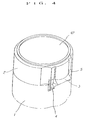
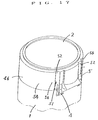
- FIG. 4 is a perspective view of the cap of the embodiment of FIG. 1 in its closed position.
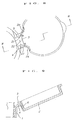
- FIG. 5 is an enlarged cross sectional partial view of the embodiment of FIG. 4, showing the relationship between the film hinge and the straps.
- FIG. 6 is an enlarged cross sectional partial view of the embodiment of FIG. 4, showing the relationship between the film hinge and the straps.
- FIG. 7 is an illustration showing loci of straps according to the invention.
- FIG. 8 is an enlarged schematic plan view of a snap-hinged cap according to the invention, showing a film hinge and portions of the skirt section to which respective straps are connected to illustrate how these components are elastically deformed when the cap starts swinging.
- FIG. 9 is a schematic cross sectional view taken along line W-W in FIG. 8.
- FIG. 10 is an enlarged plan view of the skirt section, schematically showing how it is elastically deformed when the cap is further swung from the position of FIG. 8.
- FIG. 11 is a schematic cross sectional view taken along line V-V in FIG. 10.
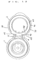
- FIG. 12 is an enlarged plan view of a second embodiment of the invention with a cap in its open position.
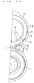
- FIG. 13 is an enlarged plan view of a half of the embodiment of FIG. 12.
- FIG. 14 is a perspective view of the cap of FIG. 12 in its closed position.
- FIG. 15 is an enlarged plan view of a third embodiment of the invention with a cap in its open position.
- FIG. 16 is an enlarged plan view of a half of the embodiment of FIG. 15.
- FIG. 17 is a perspective view of the cap of FIG. 15 in its closed position.
- FIG. 18 is an illustration showing loci of straps of a conventional snap-hinged cap.
- FIGS. 1 through 11 illustrate a first embodiment of the invention, although the profile and the dimensions are not limited to the embodiment.
- a snap-hinged cap is designed to snap fit onto a circular neck 28 of a liquid container.
- a snap-hinged cap comprises a main body section 1 of thermoplastic resin such as polyethylene, a cap 2 integrally formed and molded with the main body section 1, a film hinge 3 connecting the main body section 1 and the cap 2, and the straps 4, 5 arranged on both lateral sides of the film hinge 3.
- the cap 2 has a skirt section 6 which has a lower edge 7.
- the main body section 1 has a peripheral wall 8 which has an upper edge 9.
- the film hinge 3 has an upper surface 10 and a lower surface of a recessed section 11 having an inverted V-shape.
- the upper surface 10 of the film hinge 3 is located exactly on a plane where the lower edge 7 of the cap 2 abuts the upper edge 9 of the main body section 1.
- the peripheral wall 8 of the main body section 1 has a recessed section 13 including an end 15, and the lower edge 7 of the cap 2 has a recessed section 14 including an end 16.
- the recessed section 13 has a depth same as that of the recessed section 14.
- each of the straps 4, 5 has a connecting section 17, 18 and a bent section 19.
- Each of the straps 4, 5 is connected to the main body section 1 and the cap 2 at the ends 15, 16 with the connecting sections 17, 18.
- the ends 15, 16 and the connecting sections 17, 18 are located above and below an abutment plane 12 in which the lower edge 7 of the cap 2 abuts the upper edge 9 of the main body section 1.
- Each of said straps 4, 5 has a center line having a length S that is longer than the length T of a straight line connecting said connecting sections 17, 18.
- each of the straps 4, 5 has a compressed V-shaped lateral view.
- the bent section 19 is projected upwardly.
- the bent section 19 is projected toward a center of the cap.
- Each of the straps 4, 5 is realized in the form of a rather thick band band as a whole, and has the largest thickness at the bent section 19 and the thickness is reduced toward the connecting sections 17, 18.
- said skirt section 6 of the cap 2 has peripheral wall sections 20, 21, 22, 23 and 24 located near a connecting portion of the cap 2, the film hinge 3 and the straps 4, 5 and a remaining peripheral wall section 25.
- the peripheral wall sections 20, 21, 22, 23 and 24 near the connecting portion has a thickness smaller than that of the remaining peripheral wall section 25 so that they are apt to be elastically deformed by radial pressure applied thereto.
- each of the peripheral wall sections 20, 24 located outside the respective connecting portion of the film hinge 3 and the straps 4, 5 along an outer periphery of the cap 2 has a transversal cross sectional view concaved toward the center of the cap so as to concentrate the deformation due to the radial pressure on and near the connecting portion.
- an axis 0-0 of swinging motion of the film hinge 3 is located close to an imaginary extended surface 26 of the peripheral wall 8 of the main body section 1 and an imaginary extended surface 27 of the peripheral wall sections 25 of the skirt section 6.
- the peripheral wall sections 20, 21, 22, 23 and 24 having a reduced thickness of the skirt section 6 and the connecting sections 17, 18 of the straps 4, 5 are located inside said imaginary extended surfaces 26, 27 of the peripheral walls with regard to the center of the main body section 1 and that of the cap 2.
- Said main body section 1 is engagedly fitted onto the neck 28 of a liquid container and comprises a lower cylindrical section 30 secured to an undercut section 29 of the neck, a top wall 31 and an inner cylindrical section 32 extending downwardly from the top wall 31 and tightly held to an inner surface of the mouth-neck section 28.
- An annular wall 33 is standing from an upper surface of the top wall 31 and near the outer periphery of the top wall 31 and said upper edge 9 of the peripheral wall 8 of the main body section 1 is located outside an outer peripheral surface of the annular wall 3.
- a discharge cylinder 35 having a liquid discharging annular lip 34 is standing from the upper surface of the top wall 31 and at the inside of the annular wall 33.
- the top wall 31 is additionally provided with an easily breakable and annularly V-grooved notch 36 in the inside of the discharge cylinder 35.
- An easily removable portion 37 surrounded by the notch 36 is provided with a leg piece 38 and a tongue piece 39.
- the skirt section 6 of said cap 2 is engaged with the annular wall 33 of the main body section 1.
- the skirt section 6 has an inner diameter which is so arrange that an undercut section 40 of the cap 2 is detachably engaged with the annular wall 33 of the main body section 1.
- the cap 2 is provided with a finger hook 41 for opening the cap with a finger tip.
- the finger hook 41 is outwardly projected from the outer periphery of the skirt section 6 at a position radially opposite to the film hinge 3.
- the cap 2 has a top wall 42.
- An inner surface of the top wall 42 is provided with an annular rim 43 and an appropriate number of small aligning projections 44 which are projected from the top wall 42.
- the annular rim 43 is so designed to abut the inner surface of the annular lip 34 of said discharge cylinder 35 of the main body section 1 in order to prevent liquid from leaking therethrough.
- the small aligning projections 44 are so designed to abut the inner surface of the annular lip 34 in order to align the skirt section 6 of the cap 2 with the annular wall 33 of the main body section 1 as the former is fitted onto the latter.
- the first embodiment of the invention has a configuration as described above and operates in a manner as described below by referring to FIGS. 7 through 11.
- the cap 2 When the cap 2 is turned toward to its closed position as indicated by arrow X in FIG. 7, the cap swings or rotates around the axis 0-0 of swinging motion of the film hinge 3.
- the connecting section 18 connecting the strap 4 and the skirt section 6 of the cap 2 rotates around the connecting section 17 (connecting the strap 4 and the peripheral wall 8 of the main body section 1) as a pivot.
- the connecting section 18 of the strap 4 is a free end, the connecting section 18 would draw a locus of rotation P as it rotates. If the connecting section 17 of the strap 4 is a free end, the connecting section 18 would draw a locus of rotation Q as it rotates.
- both the connecting sections 17, 18 are connected to the main body section 1 and the cap 2, the rotary motion of the strap 4 is restrained curbed by the skirt section 6 of the cap 2 to such a motion as described below.
- the curved connecting sections 17, 18 of the strap 4 and the bent section 19 are elastically deformed to eventually become substantially straight and make the strap 4 longer by distance T shown in FIG. 7.
- This tensile force acts on the peripheral wall sections 20, 21, 22, 23 and 24 to elastically deform them in the outward direction of the skirt section 6 as indicated by solid lines in FIGS. 8 and 9.
- peripheral wall sections 20 through 24 The elastic outward deformation of the peripheral wall sections 20 through 24 is concentrated at and around the connecting sections of the film hinge 3 and the straps 4 and 5 because the peripheral wall sections 20, 24 have a transversal cross sectional view concaved toward the center of the cap.
- the elastic outward deformation of the peripheral wall sections 20 through 24 begins when the connecting sections 17, 18 and the bent section 19 of the strap 4 are elastically deformed to become substantially straight.
- the length of the straight line connecting the connecting sections 17, 18 of the strap 4 in case of the closed position of the cap 2 is slightly shorter than the length of the corresponding line when the cap 2 is in its open position.
- the strap 4 is laterally depressed to show a slightly sharper V-shape so that the cap 2 in the closed position is subjected to a consequent restitutive force that slightly urges it to rotate in the direction indicated by arrow Y.
- the detachable engagement of the annular wall 33 of the main body section 1 and the undercut section 40 of the skirt section 6 of the cap 2 is designed to hold the cap 2 constantly in its closed position against the rotary force Y applied to the cap.
- FIGS. 8, 9, 10 and 11 show the position of the peripheral wall of the skirt section before it is elastically deformed.
- the main body section of the illustrated embodiment is engaged with the cylindrical neck 28 of the liquid container by press fitting, it may alternatively be engaged with the neck by screw fitting.
- the snap-hinged cap may have alternatively an elliptic or angular cross section depending on the profile of the neck.
- the container main body having an opening may be used as the main body section of a snap-hinged cap according to the invention.
- the present invention is not limited to the construction illustrated in the drawings.
- FIGS. 12, 13 and 14 illustrate a second embodiment of the invention, although the profile and the dimensions are not limited to the those of the drawings.
- the peripheral wall sections 20, 24 located near the respective straps 4, 5 have a transversal cross sectional view concaved toward the center of the cap.
- the second embodiment differs from the first embodiment as described below.
- the cap 2 has a skirt section 46.
- the skirt section 46 has an inner peripheral wall 47.
- the skirt section 46 comprises a thin portion 45 near the straps 4, 5 and a remaining portion.
- the thin portion 45 comprises an inner peripheral wall 48 having a transversal cross sectional view convexed outwardly and formed on the inner peripheral wall 47 of the the skirt section 46, and an outer peripheral surface 49.
- the outer peripheral surface 49 of the thin portion 45 is continuously and smoothly extending from an outer peripheral surface 50 of the remaining portion of the skirt section 46 to produce a unitary outer peripheral surface.
- the second embodiment has the construction and the effect same as those of the first embodiment except the construction that the outer peripheral surface 49 of the thin portion 45 is continuously and smoothly extending from the outer peripheral surface 50 of the remaining portion to produce a unitary outer peripheral surface of the skirt section as illustrated in FIG. 14.
- the second embodiment provides a good appearance.
- the hingered-snap cap is rolled in a conveying operation using a hopper more smoothly compared to the first embodiment so as to enhance the rate of conveying operation.
- FIGS. 15, 16 and 17 illustrate a third embodiment of the invention, although the profile and the dimensions are not limited to the those of the drawings.
- the third embodiment differs from the above first and second embodiments as follows.
- the skirt section 46 includes a thin portion 51 near the straps 4, 5.
- the skirt section 46 has an inner peripheral surface 53.
- the thin portion 51 includes a thin peripheral wall section 52 which has a transversal cross sectional view concaved toward the center of the cap 2, and a notch 55 provided opposite to the straps 4, 5 relating to the thin peripheral wall section 52.
- the notch 55 is positioned away from the thin peripheral wall section 52 by a small distance W.
- the notch 55 is cut into the skirt section 46 from the inner peripheral surface 53 toward the outer peripheral surface 54.
- the thin portion 51 includes an outer peripheral surface 56 between the thin peripheral wall section 52 and the notch 55.
- the third embodiment has the construction and the effect same as those of the first and second embodiments except the construction of the thin portion 51.
- the thin portions 51 of the skirt section has the outer peripheral surface 56 which is continuously and smoothly extending from the outer peripheral surface 54 of the outer peripheral surface 54 of the skirt section 46.
- the entire length of the outer peripheral surface of the skirt section is made longer than that of the first embodiment, so that the cap provides a good appearance.
- the hinged-snap cap is rolled in a conveying operation using a hopper more smoothly compared to the first embodiment.
- the thin portion 51 between the thin peripheral wall section 52 and the notch 55 has a thickness thicker than that of the first and second embodiments, the resiliency can be improved compared to the first and second embodiments.
- the snap effect of the cap during the opening and closing motion of the cap is realized by the elastic resiliency produced as a result of elastic deformation of the straps and that of the peripheral walls of the skirt section of the cap having a reduced thickness and therefore the straps are practically not subjected to tensile force, the straps are made free from degradation in the strength to prolong the service life of the snap-hinged cap.
- the portions of the straps projecting outward from the outer peripheral surface of the snap-hinged cap can be dimensionally minimized to improve the appearance of the snap-hinged cap.
- the straps show large elastic resiliency after elastic deformation, they can produce a good snap effect.
- each of the portions of the skirt section of the cap formed outside the straps comprises a peripheral wall section that can be easily and elastically deformed, the straps can be effectively prevented from being subjected to external tensile force.
- each of the portions of the skirt section of the cap formed outside the straps and having a reduced thickness comprises an outer peripheral surface continuously and smoothly extending from the outer peripheral surface of the remaining portion of the skirt section, the snap-hinged cap provides a good appearance and can adapt itself stably to bottling operation in a bottling line using a hopper to enhance the rate of bottling operation.
- each of the portions of the skirt section of the cap formed close to the straps and having a reduced thickness makes the outer peripheral surface of the cap transversally long to a certain extent, the snap-hinged cap can adapt itself more stably to bottling operation in a bottling line and the resiliency of the portions of the skirt section having a reduced thickness can be improved to some extent. Additionally, an outer peripheral surface provided between the peripheral wall showing a convexed cross sectional view and the notch of each of said portions having a reduced thickness improves the resiliency of those portions to some extent.
- the container can adapt itself excellently to packaging operation using thin film.
- the skirt section is elastically deformed to absorb and dissipate external tensile force applied to the straps and eliminate any tensile stress in the straps at an angular position of the cap where the straps are maximally expanded to improve the service life of the straps.
Landscapes
- Engineering & Computer Science (AREA)
- Mechanical Engineering (AREA)
- Closures For Containers (AREA)
Abstract
Description
- This invention relates to an improved to a snap-hinged cap to be mainly used to close and open a liquid discharge opening with a snap motion.
- A snap-hinged cap is to be used close and open a liquid discharge opening is already known from Japanese Patent Publication No. 3-53182.
- As shown in FIG. 18, a snap-hinged cap disclosed in the above patent publication is provided with a film hinge A and a pair of straps B arranged along the respective lateral sides of and slightly below the film hinge. Thus, the film hinge and the straps mutually connect a main body section C and a cap D.
- However, with a snap-hinged cap having a configuration as described above, the straps B are made substantially straight when the cap D is opened, although the straps B have a length shorter than the arc traced by the cap D when it is swung open or closed, and expanded to operate as springs when the straps are moving so that they are held under stress when the cap D is in an intermediary position between the closed position and the opened position.
- More specifically, with a snap-hinged cap as disclosed in the above patent publication and illustrated in FIG. 18, each of the points F connecting the respective straps B and the cap D traces an arc E as the cap D swings around the
axis 0 of swinging motion of the film hinge A. - On the other hand, as the cap D swings, the straps B swing around the respective points G connecting the straps and the main body section C so that the connection points F are supposed to trace respective arcs H as free ends.
- However, in reality, the connecting points move with the cap D and traces respective arcs E to expand the strap B by a distance E.
- For each of the straps B, the distance E of expansion is a sum of an amount L1 of deformation of the strap B at the connecting points F and G where it is hooked and an amount L2 of expansion of the strap B that gives rise to the above spring effect.
- When the cap D takes its closed position relative to the main body section C, the strap B are held to a curved state as indicated by broken lines I in FIG. 18.
- In order to generate the amount L2 of expansion, only the straps B have to be subjected to strong external tensile force repeatedly so that they may lose their mechanical strength, with their surface layers getting exfoliated with time, until they eventually break down.
- In view of the above identified problem of known snap-hinged caps, it is therefore an object of the present invention to provide a snap-hinged cap comprising straps that are not subjected to strong external tensile force and hence not accompanied by the problem of losing their mechanical strength and producing exfoliated surface layers, if the cap is repeatedly opened and closed, so that the snap-hinged cap can maintain its snap effect without requiring the use of a complicated structure and that of synthetic resin by an increased amount and affecting adversely to capping, packaging and related operations.
- In order to solve the above problem, according to the invention, there is provided a snap-hinged cap comprising a main body section of thermoplastic synthetic resin, a cap integrally molded with the main body section, a film hinge connecting the main body section and the cap, and straps arranged on both lateral sides of the film hinge, wherein
- said cap includes a skirt section which includes a lower edge,
- said main body section includes a peripheral wall,
- said film hinge connects a portion of the lower edge of the skirt section of the cap and the peripheral wall of the main body section,
- said straps are connected to the main body section and the cap at connecting sections, said connecting sections being arranged above and below an abutting surface of the lower edge of the skirt section of the cap and the main body section in case of the cap being closed,
- each of said straps having a center line longer than a straight line between the connecting sections, and
- said skirt section of the cap having a peripheral wall which comprises a thin portion located adjacent to the film hinge and the straps and a remaining portion.
- According to the invention, since each of the straps connecting the main body section and the cap and arranged along the respective lateral sides of the film hinge has a center line longer than the straight line between the opposite ends thereof connected respectively to the main body section and the cap and the skirt section of the cap has a peripheral wall having a wall thickness reduced in portions located adjacent to the film hinge and the respective straps from the wall thickness in the remaining portion, the situation where the straps are made short and not sufficient to accommodate the swinging motion of the cap and the insufficiency in the length of the straps is compensated by elastic deformation of the straps and that of the thin areas of the skirt section to make the film hinge and the straps subjected to excessive external tensile force as in the case of conventional snap-hinged caps is effectively prevented and the straps shows elastic resiliency to give rise to a good snap effect.
- Each of the straps may have a compressed V-shaped lateral view and a bent section. The bent section is projected toward a center of the cap when the cap is closed, and the bent section is projected upwardly when the cap is opened. Since each of the straps shows a mildly V-shaped lateral view, it can be easily extended and elastically deformed to stretch itself into a straight form. Additionally, since the bent sections of the mildly V-shaped straps project toward the central axis of the cap when the cap is closed, the portions of the straps projecting outward from the outer peripheral surface of the snap-hinged cap can be dimensionally minimized.
- Each of the straps may have the largest thickness at the respective bent sections of compressed V-shape. Since the straps have the largest thickness at the respective bent sections of their mild V-shapes, they show a strong elastic resiliency when they are elastically deformed and stretched into an almost straight form.
- Said thin portion may include a transversal cross sectional view concaved toward a center of the cap. Since each of the portions of the skirt section of the cap formed outside the straps and having a reduced thickness comprises a peripheral wall section having a transversal cross sectional view concaved toward the center of the cap, those portions can be easily and elastically deformed to reduce any external tensile force to which the straps are subjected.
- Said skirt section of the cap may include a thin portion. The thin portion comprises an inner peripheral wall having a transversal cross sectional view convexed outwardly and formed on an inner peripheral wall of the skirt section, and an outer peripheral surface which is continuously and smoothly extending from an outer peripheral surface of the skirt section. Since each of the portions of the skirt section of the cap formed outside the straps and having a reduced thickness comprises a peripheral wall section having a transversal cross sectional view convexed toward the center of the cap and an outer peripheral surface continuously and smoothly extending from the outer peripheral surface of the remaining portion of the skirt section, the snap-hinged cap provides a good appearance and can adapt itself stably to bottling operation in a bottling line using a hopper to enhance the rate of bottling operation.
- The thin portion may include a thin peripheral wall section having a transversal cross sectional view concaved toward a center of the cap, and a notch provided opposite to the straps relating to the thin peripheral wall section. Since each of the portions of the skirt section of the cap formed outside the straps and having a reduced thickness makes the outer peripheral surface of the cap transversally longer to a certain extent than its counterpart of a snap-hinged cap according to
claim 1 orclaim 4, the snap-hinged cap can adapt itself more stably to bottling operation in a bottling line and the resiliency of the portions of the skirt section having a reduced thickness can be improved to some extent. - The peripheral wall of the main body section may have a cylindrical shape, and the skirt section of the cap may have a cylindrical shape. The skirt section has thin peripheral wall sections. Connecting portions of the hinges and the skirt section, an axis of rotating motion of the film hinge and the thin peripheral wall sections are arranged near an imaginary extended surface of the peripheral wall and an imaginary extended surface of a thicker peripheral wall sections of the skirt section. Since only a couple of members project by a short distance from the outer peripheral surface of the cylindrical container comprising a main body section and a cap as integral components when the cap is in its closed position, the container can adapt itself excellently to packaging operation.
- When the cap is opened and closed, the thin peripheral wall sections are elastically deformed to prevent the film hinge and the straps from being subjected to concentrated tensile stress. The skirt section is elastically deformed to absorb and dissipate external tensile force applied to the straps and eliminate any tensile stress in the straps at an angular position of the cap where the straps are maximally expanded.
- FIG. 1 is an enlarged plan view of a first embodiment of the invention with a cap in its open position.
- FIG. 2 is a further enlarged plan view of a half of the embodiment of FIG. 1.
- FIG. 3 is an enlarged cross sectional view of the embodiment of FIG. 1 taken along line Z-Z in FIG. 1.
- FIG. 4 is a perspective view of the cap of the embodiment of FIG. 1 in its closed position.
- FIG. 5 is an enlarged cross sectional partial view of the embodiment of FIG. 4, showing the relationship between the film hinge and the straps.
- FIG. 6 is an enlarged cross sectional partial view of the embodiment of FIG. 4, showing the relationship between the film hinge and the straps.
- FIG. 7 is an illustration showing loci of straps according to the invention.
- FIG. 8 is an enlarged schematic plan view of a snap-hinged cap according to the invention, showing a film hinge and portions of the skirt section to which respective straps are connected to illustrate how these components are elastically deformed when the cap starts swinging.
- FIG. 9 is a schematic cross sectional view taken along line W-W in FIG. 8.
- FIG. 10 is an enlarged plan view of the skirt section, schematically showing how it is elastically deformed when the cap is further swung from the position of FIG. 8.
- FIG. 11 is a schematic cross sectional view taken along line V-V in FIG. 10.
- FIG. 12 is an enlarged plan view of a second embodiment of the invention with a cap in its open position.
- FIG. 13 is an enlarged plan view of a half of the embodiment of FIG. 12.
- FIG. 14 is a perspective view of the cap of FIG. 12 in its closed position.
- FIG. 15 is an enlarged plan view of a third embodiment of the invention with a cap in its open position.
- FIG. 16 is an enlarged plan view of a half of the embodiment of FIG. 15.
- FIG. 17 is a perspective view of the cap of FIG. 15 in its closed position.
- FIG. 18 is an illustration showing loci of straps of a conventional snap-hinged cap.
- FIGS. 1 through 11 illustrate a first embodiment of the invention, although the profile and the dimensions are not limited to the embodiment.
- The illustrated embodiment of snap-hinged cap is designed to snap fit onto a
circular neck 28 of a liquid container. As shown in FIGS. 1, 2, 3 and 4, a snap-hinged cap comprises amain body section 1 of thermoplastic resin such as polyethylene, acap 2 integrally formed and molded with themain body section 1, afilm hinge 3 connecting themain body section 1 and thecap 2, and thestraps film hinge 3. - The
cap 2 has askirt section 6 which has alower edge 7. Themain body section 1 has aperipheral wall 8 which has anupper edge 9. When thecap 2 is closed, thelower edge 7 of thecap 2 abuts theupper edge 9 of themain body section 1. Thefilm hinge 3 has anupper surface 10 and a lower surface of a recessedsection 11 having an inverted V-shape. Theupper surface 10 of thefilm hinge 3 is located exactly on a plane where thelower edge 7 of thecap 2 abuts theupper edge 9 of themain body section 1. - The
peripheral wall 8 of themain body section 1 has a recessedsection 13 including anend 15, and thelower edge 7 of thecap 2 has a recessedsection 14 including anend 16. The recessedsection 13 has a depth same as that of the recessedsection 14. As illustrated in FIGS. 4, 5 and 6, each of thestraps section bent section 19. Each of thestraps main body section 1 and thecap 2 at theends sections sections abutment plane 12 in which thelower edge 7 of thecap 2 abuts theupper edge 9 of themain body section 1. - Each of said
straps sections - As apparent from FIGS. 5 and 6, each of the
straps cap 2 is opened, thebent section 19 is projected upwardly. When thecap 2 is closed, thebent section 19 is projected toward a center of the cap. Each of thestraps bent section 19 and the thickness is reduced toward the connectingsections - As clearly seen from FIGS. 1, 2 and 3, said
skirt section 6 of thecap 2 hasperipheral wall sections cap 2, thefilm hinge 3 and thestraps peripheral wall section 25. Theperipheral wall sections peripheral wall section 25 so that they are apt to be elastically deformed by radial pressure applied thereto. - In particular, each of the
peripheral wall sections film hinge 3 and thestraps cap 2 has a transversal cross sectional view concaved toward the center of the cap so as to concentrate the deformation due to the radial pressure on and near the connecting portion. - As illustrated in FIG. 2, an axis 0-0 of swinging motion of the
film hinge 3 is located close to an imaginaryextended surface 26 of theperipheral wall 8 of themain body section 1 and an imaginaryextended surface 27 of theperipheral wall sections 25 of theskirt section 6. theperipheral wall sections skirt section 6 and the connectingsections straps extended surfaces main body section 1 and that of thecap 2. - Said
main body section 1 is engagedly fitted onto theneck 28 of a liquid container and comprises a lowercylindrical section 30 secured to an undercutsection 29 of the neck, atop wall 31 and an innercylindrical section 32 extending downwardly from thetop wall 31 and tightly held to an inner surface of the mouth-neck section 28. - An
annular wall 33 is standing from an upper surface of thetop wall 31 and near the outer periphery of thetop wall 31 and saidupper edge 9 of theperipheral wall 8 of themain body section 1 is located outside an outer peripheral surface of theannular wall 3. - A
discharge cylinder 35 having a liquid dischargingannular lip 34 is standing from the upper surface of thetop wall 31 and at the inside of theannular wall 33. - The
top wall 31 is additionally provided with an easily breakable and annularly V-groovednotch 36 in the inside of thedischarge cylinder 35. An easilyremovable portion 37 surrounded by thenotch 36 is provided with aleg piece 38 and atongue piece 39. - The
skirt section 6 of saidcap 2 is engaged with theannular wall 33 of themain body section 1. Theskirt section 6 has an inner diameter which is so arrange that an undercutsection 40 of thecap 2 is detachably engaged with theannular wall 33 of themain body section 1. Thecap 2 is provided with afinger hook 41 for opening the cap with a finger tip. Thefinger hook 41 is outwardly projected from the outer periphery of theskirt section 6 at a position radially opposite to thefilm hinge 3. - The
cap 2 has atop wall 42. An inner surface of thetop wall 42 is provided with anannular rim 43 and an appropriate number of small aligningprojections 44 which are projected from thetop wall 42. Theannular rim 43 is so designed to abut the inner surface of theannular lip 34 of saiddischarge cylinder 35 of themain body section 1 in order to prevent liquid from leaking therethrough. The small aligningprojections 44 are so designed to abut the inner surface of theannular lip 34 in order to align theskirt section 6 of thecap 2 with theannular wall 33 of themain body section 1 as the former is fitted onto the latter. - The first embodiment of the invention has a configuration as described above and operates in a manner as described below by referring to FIGS. 7 through 11.
- When the
cap 2 is in an open position as indicated by solid lines in FIG. 7, thefilm hinge 3 is flat and thestrap 4 is held stationary with thebent section 19 facing upward. - When the
cap 2 is turned toward to its closed position as indicated by arrow X in FIG. 7, the cap swings or rotates around the axis 0-0 of swinging motion of thefilm hinge 3. The connectingsection 18 connecting thestrap 4 and theskirt section 6 of thecap 2 rotates around the connecting section 17 (connecting thestrap 4 and theperipheral wall 8 of the main body section 1) as a pivot. - If the connecting
section 18 of thestrap 4 is a free end, the connectingsection 18 would draw a locus of rotation P as it rotates. If the connectingsection 17 of thestrap 4 is a free end, the connectingsection 18 would draw a locus of rotation Q as it rotates. - However, since both the connecting
sections main body section 1 and thecap 2, the rotary motion of thestrap 4 is restrained curbed by theskirt section 6 of thecap 2 to such a motion as described below. - Namely, as the
cap 2 swings further, the curved connectingsections strap 4 and thebent section 19 are elastically deformed to eventually become substantially straight and make thestrap 4 longer by distance T shown in FIG. 7. - However, since the strap is still short of the required length with regard to the locus of rotation Q by distance U indicated in FIG. 7, the
skirt section 6 of thecap 2 is subjected to tensile force trying to compensate the distance U or the shortage of length. - This tensile force acts on the
peripheral wall sections skirt section 6 as indicated by solid lines in FIGS. 8 and 9. - The elastic outward deformation of the
peripheral wall sections 20 through 24 is concentrated at and around the connecting sections of thefilm hinge 3 and thestraps peripheral wall sections - The elastic outward deformation of the
peripheral wall sections 20 through 24 begins when the connectingsections bent section 19 of thestrap 4 are elastically deformed to become substantially straight. - The shortage of distance U in FIG. 7 is compensated by the elastic outward deformation of the
peripheral wall sections 20 through 24 so that the connectingsection 18 of thestrap 4 rotates to draw a locus of rotation R to take a position as indicated by dotted lines in FIG. 7 corresponding to the closed position of thecap 2. - As apparent from FIG. 7, the length of the straight line connecting the connecting
sections strap 4 in case of the closed position of thecap 2 is slightly shorter than the length of the corresponding line when thecap 2 is in its open position. Thus, thestrap 4 is laterally depressed to show a slightly sharper V-shape so that thecap 2 in the closed position is subjected to a consequent restitutive force that slightly urges it to rotate in the direction indicated by arrow Y. - The detachable engagement of the
annular wall 33 of themain body section 1 and the undercutsection 40 of theskirt section 6 of thecap 2 is designed to hold thecap 2 constantly in its closed position against the rotary force Y applied to the cap. - Since the thin peripheral wall sections 20-24 of the
skirt 6 of thecap 2 is elastically deformed when thecap 2 is rotated as illustrated in FIGS. 8 and 9, such elastic deformation of the thin peripheral wall sections 20-24 pulls the remainingwall section 25 having a thicker thickness toward themain body section 1 as illustrated in FIGS. 10 and 11, so that theskirt section 6 becomes to appear slightly elliptic as a whole. - The above described deformation becomes maximal when the
cap 2 is rotated or swung by an angle equal to a 1/2 of the total rotating or swingable angle, when the snapping effect of the cap is generated. - Note that the dotted lines in FIGS. 8, 9, 10 and 11 show the position of the peripheral wall of the skirt section before it is elastically deformed.
- While the main body section of the illustrated embodiment is engaged with the
cylindrical neck 28 of the liquid container by press fitting, it may alternatively be engaged with the neck by screw fitting. The snap-hinged cap may have alternatively an elliptic or angular cross section depending on the profile of the neck. The container main body having an opening may be used as the main body section of a snap-hinged cap according to the invention. The present invention is not limited to the construction illustrated in the drawings. - FIGS. 12, 13 and 14 illustrate a second embodiment of the invention, although the profile and the dimensions are not limited to the those of the drawings.
- In the first embodiment illustrated in FIG. 1, the
peripheral wall sections respective straps cap 2 has askirt section 46. Theskirt section 46 has an innerperipheral wall 47. Theskirt section 46 comprises athin portion 45 near thestraps thin portion 45 comprises an innerperipheral wall 48 having a transversal cross sectional view convexed outwardly and formed on the innerperipheral wall 47 of the theskirt section 46, and an outerperipheral surface 49. - The outer
peripheral surface 49 of thethin portion 45 is continuously and smoothly extending from an outerperipheral surface 50 of the remaining portion of theskirt section 46 to produce a unitary outer peripheral surface. - In other words, the second embodiment has the construction and the effect same as those of the first embodiment except the construction that the outer
peripheral surface 49 of thethin portion 45 is continuously and smoothly extending from the outerperipheral surface 50 of the remaining portion to produce a unitary outer peripheral surface of the skirt section as illustrated in FIG. 14. - Since the outer
peripheral surface 49 and the outerperipheral surface 50 form a unitary outer peripheral surface according to the second embodiment, the second embodiment provides a good appearance. In addition, the hingered-snap cap is rolled in a conveying operation using a hopper more smoothly compared to the first embodiment so as to enhance the rate of conveying operation. - FIGS. 15, 16 and 17 illustrate a third embodiment of the invention, although the profile and the dimensions are not limited to the those of the drawings.
- The third embodiment differs from the above first and second embodiments as follows. The
skirt section 46 includes athin portion 51 near thestraps skirt section 46 has an innerperipheral surface 53. Thethin portion 51 includes a thinperipheral wall section 52 which has a transversal cross sectional view concaved toward the center of thecap 2, and anotch 55 provided opposite to thestraps peripheral wall section 52. In other words, thenotch 55 is positioned away from the thinperipheral wall section 52 by a small distance W. Thenotch 55 is cut into theskirt section 46 from the innerperipheral surface 53 toward the outerperipheral surface 54. Thethin portion 51 includes an outerperipheral surface 56 between the thinperipheral wall section 52 and thenotch 55. - The third embodiment has the construction and the effect same as those of the first and second embodiments except the construction of the
thin portion 51. - In this third embodiment, since the
thin portions 51 of the skirt section has the outerperipheral surface 56 which is continuously and smoothly extending from the outerperipheral surface 54 of the outerperipheral surface 54 of theskirt section 46. Thus, according to the third embodiment, the entire length of the outer peripheral surface of the skirt section is made longer than that of the first embodiment, so that the cap provides a good appearance. In addition, since the third embodiment has continuously and smoothly outer peripheral surface compared to the first embodiment, the hinged-snap cap is rolled in a conveying operation using a hopper more smoothly compared to the first embodiment. - In addition, the
thin portion 51 between the thinperipheral wall section 52 and thenotch 55 has a thickness thicker than that of the first and second embodiments, the resiliency can be improved compared to the first and second embodiments. - According to the invention, since the snap effect of the cap during the opening and closing motion of the cap is realized by the elastic resiliency produced as a result of elastic deformation of the straps and that of the peripheral walls of the skirt section of the cap having a reduced thickness and therefore the straps are practically not subjected to tensile force, the straps are made free from degradation in the strength to prolong the service life of the snap-hinged cap.
- Since the bent sections of the straps project toward the central axis of the cap when the cap is closed, the portions of the straps projecting outward from the outer peripheral surface of the snap-hinged cap can be dimensionally minimized to improve the appearance of the snap-hinged cap.
- Since the straps show large elastic resiliency after elastic deformation, they can produce a good snap effect.
- Since each of the portions of the skirt section of the cap formed outside the straps comprises a peripheral wall section that can be easily and elastically deformed, the straps can be effectively prevented from being subjected to external tensile force.
- Since each of the portions of the skirt section of the cap formed outside the straps and having a reduced thickness comprises an outer peripheral surface continuously and smoothly extending from the outer peripheral surface of the remaining portion of the skirt section, the snap-hinged cap provides a good appearance and can adapt itself stably to bottling operation in a bottling line using a hopper to enhance the rate of bottling operation.
- Since each of the portions of the skirt section of the cap formed close to the straps and having a reduced thickness makes the outer peripheral surface of the cap transversally long to a certain extent, the snap-hinged cap can adapt itself more stably to bottling operation in a bottling line and the resiliency of the portions of the skirt section having a reduced thickness can be improved to some extent. Additionally, an outer peripheral surface provided between the peripheral wall showing a convexed cross sectional view and the notch of each of said portions having a reduced thickness improves the resiliency of those portions to some extent.
- Since only a couple of members project by a short distance from the outer peripheral surface of the cylindrical container comprising a main body section and a cap as integral components when the cap is in its closed position, the container can adapt itself excellently to packaging operation using thin film.
- The skirt section is elastically deformed to absorb and dissipate external tensile force applied to the straps and eliminate any tensile stress in the straps at an angular position of the cap where the straps are maximally expanded to improve the service life of the straps.
Claims (2)
- A snap-hinged cap comprising a main body section (1) of thermoplastic synthetic resin, a cap (2) integrally molded with the main body section (1), a film hinge (3) connecting the main body section (1) and the cap (2), and straps (4, 5) arranged on both lateral sides of the film hinge (3), whereinsaid cap (2) includes a skirt section (6, 46) which includes a lower edge (7),said main body section (1) includes a peripheral wall (8),said film hinge (3) connects a portion of the lower edge (7) of the skirt section (6, 46) of the cap (2) and the peripheral wall (8) of the main body section (1),said straps (4, 5) are connected to the main body section (1) and the cap (2) at connecting sections (17, 18), said connecting sections (17, 18) being arranged above and below an abutting surface (12) of the lower edge (7) of the skirt section (6, 46) of the cap (2) and the main body section (1) in case of the cap (2) being closed.each of said straps (4, 5) having a center line longer than a straight line between the connecting sections (17, 18), andsaid skirt section (46) of the cap (2) includes a thin portion (45) near the straps (4, 5), andthe thin portion (45) comprises an inner peripheral wall (48) having a transversal cross sectional view convexed outwardly and formed on an inner peripheral wall (47) of the skirt section (46), and an outer peripheral surface (49) which is continuously and smoothly extending from an outer peripheral surface of the skirt section (46).
- A snap-hinged cap comprising a main body section (1) of thermoplastic synthetic resin, a cap (2) integrally molded with the main body section (1), a film hinge (3) connecting the main body section (1) and the cap (2), and straps (4, 5) arranged on both lateral sides of the film hinge (3), whereinsaid cap (2) includes a skirt section (6, 46) which includes a lower edge (7),said main body section (1) includes a peripheral wall (8),said film hinge (3) connects a portion of the lower edge (7) of the skirt section (6, 46) of the cap (2) and the peripheral wall (8) of the main body section (1),said straps (4, 5) are connected to the main body section (1) and the cap (2) at connecting sections (17, 18), said connecting sections (17, 18) being arranged above and below an abutting surface (12) of the lower edge (7) of the skirt section (6, 46) of the cap (2) and the main body section (1) in case of the cap (2) being closed,each of said straps (4, 5) having a center line longer than a straight line between the connecting sections (17, 18), andthe skirt section (46) includes a thin portion (51) near the straps (4, 5), andthe thin portion (51) includes a thin peripheral wall section (52) having a transversal cross sectional view concaved toward a center of the cap (2), and a notch (55) provided opposite to the straps (4, 5) relating to the thin peripheral wall section (52).
Applications Claiming Priority (3)
| Application Number | Priority Date | Filing Date | Title |
|---|---|---|---|
| JP5048295 | 1995-02-15 | ||
| JP50482/95 | 1995-02-15 | ||
| JP05048295A JP3287973B2 (en) | 1994-02-15 | 1995-02-15 | Snap hinge cap |
Publications (3)
| Publication Number | Publication Date |
|---|---|
| EP0727361A2 true EP0727361A2 (en) | 1996-08-21 |
| EP0727361A3 EP0727361A3 (en) | 1997-02-12 |
| EP0727361B1 EP0727361B1 (en) | 2000-07-12 |
Family
ID=12860141
Family Applications (1)
| Application Number | Title | Priority Date | Filing Date |
|---|---|---|---|
| EP96301048A Expired - Lifetime EP0727361B1 (en) | 1995-02-15 | 1996-02-15 | Snap-hinged cap |
Country Status (5)
| Country | Link |
|---|---|
| US (1) | US5785193A (en) |
| EP (1) | EP0727361B1 (en) |
| AU (1) | AU707269B2 (en) |
| CA (1) | CA2169486C (en) |
| DE (1) | DE69609210T2 (en) |
Cited By (9)
| Publication number | Priority date | Publication date | Assignee | Title |
|---|---|---|---|---|
| EP0873944A1 (en) * | 1997-04-21 | 1998-10-28 | Owens-Illinois Closure Inc., | Closure with snap-type hinge cap |
| EP1000869A1 (en) * | 1998-11-16 | 2000-05-17 | L'oreal | Articulated assembly using a hinge with biasing means for opening and closing |
| WO2000037328A1 (en) * | 1998-12-18 | 2000-06-29 | Rigo Mihaly | Closing cap |
| US6484731B1 (en) | 1999-03-16 | 2002-11-26 | L'oreal | Single-piece articulated assembly |
| DE10160362A1 (en) * | 2001-12-08 | 2003-06-26 | Saint Gobain Oberland Ag | Closure cap, in particular, for a Glass bottle comprises at least one catch protrusion which interacts with the at least one undercut on the bottle neck section |
| WO2006064683A1 (en) | 2004-12-16 | 2006-06-22 | Unitika Ltd. | Hinged cap having biodegradability |
| EP1790581A3 (en) * | 2005-11-24 | 2007-08-15 | Weener Plastik AG | Hinged closure |
| US7618207B2 (en) | 2004-09-10 | 2009-11-17 | L'oreal | Device for packaging and applying a product equipped with a detachable applicator element |
| EP3817988A1 (en) * | 2018-07-04 | 2021-05-12 | Weener Plastik GmbH | Flap closure |
Families Citing this family (47)
| Publication number | Priority date | Publication date | Assignee | Title |
|---|---|---|---|---|
| US5992659A (en) * | 1997-09-25 | 1999-11-30 | Pano Cap (Canada) Limited | Tamper proof flip top cap |
| USD509426S1 (en) | 1997-10-28 | 2005-09-13 | Gateway Plastics, Inc. | Integrally-formed closure for a container |
| USD426772S (en) * | 1999-02-22 | 2000-06-20 | Poly-Seal Corporation | Dispensing jar cover |
| USD440494S1 (en) | 1999-11-29 | 2001-04-17 | The Procter & Gamble Company | Closure |
| US6116477A (en) * | 1999-12-13 | 2000-09-12 | Courtesy Corporation | Two piece hinge closure |
| USD443450S1 (en) | 2000-03-30 | 2001-06-12 | Johnson & Johnson Consumer Companies, Inc. | Dispenser |
| US6321923B1 (en) | 2000-04-26 | 2001-11-27 | Seaquist Closures Foreign, Inc. | Bistable hinge with reduced stress regions |
| AU9535201A (en) * | 2000-10-20 | 2002-04-29 | Louis Lagler | Sealing device for drink packages |
| US6578744B2 (en) * | 2001-03-22 | 2003-06-17 | Crown Cork & Seal Technologies Corporation | Watertight tube closure |
| AU2003269010B2 (en) * | 2002-07-12 | 2009-12-10 | Bericap | Closure comprising a hinged cap moulded in closed position |
| US20050116382A1 (en) * | 2002-07-12 | 2005-06-02 | Philippe Nusbaum | Closure device comprising a hinged cap moulded in the closed position |
| US20050173367A1 (en) * | 2002-07-12 | 2005-08-11 | Philippe Nusbaum | Closure device comprising a hinged cap moulded in the closed position |
| USD513452S1 (en) | 2002-09-27 | 2006-01-10 | Gateway Plastics, Inc. | Closure for a container |
| US7134575B2 (en) | 2002-12-21 | 2006-11-14 | Gateway Plastics, Inc. | Closure for a container |
| US20040232169A1 (en) * | 2003-05-23 | 2004-11-25 | Alberto-Culver Company | Dispenser and related dispensing method |
| USD519369S1 (en) | 2003-05-23 | 2006-04-25 | Alberto-Culver Company | Lotion dispenser |
| USD514935S1 (en) * | 2004-04-08 | 2006-02-14 | Apc Products Limited | Vent plug with internal frangible valve, internal latches and resealable cap |
| USD532691S1 (en) | 2004-11-20 | 2006-11-28 | Gateway Plastics, Inc. | Closure for a container |
| USD532298S1 (en) | 2004-11-20 | 2006-11-21 | Gateway Plastics, Inc. | Closure for a container |
| USD533452S1 (en) | 2004-11-20 | 2006-12-12 | Gateway Plastics, Inc. | Closure for a container |
| US7510095B2 (en) | 2005-03-11 | 2009-03-31 | Berry Plastics Corporation | System comprising a radially aligned container and closure |
| US7731042B2 (en) * | 2005-12-21 | 2010-06-08 | Seaquist Closures Foreign, Inc. | Closure with hinged lid and stress relief recesses |
| US20070251909A1 (en) * | 2006-04-27 | 2007-11-01 | Gilles Decelles | Flip-top closure cap |
| US20090242502A1 (en) * | 2008-03-28 | 2009-10-01 | Jack Jie Qin | Flip-cap arrangement for container |
| USD613599S1 (en) | 2009-09-11 | 2010-04-13 | Telebrands Corp. | Beverage container closure with pressure release |
| US20110062159A1 (en) * | 2009-09-11 | 2011-03-17 | Ajit Khubani | Beverage container closure with pressure release |
| US8899437B2 (en) | 2012-01-20 | 2014-12-02 | Gateway Plastics, Inc. | Closure with integrated dosage cup |
| US8955705B2 (en) | 2012-03-26 | 2015-02-17 | Gateway Plastics, Inc. | Closure for a container |
| USD679181S1 (en) | 2012-03-26 | 2013-04-02 | Gateway Plastics, Inc. | Closure for a container |
| US9475623B2 (en) | 2012-03-26 | 2016-10-25 | Gateway Plastics, Inc. | Closure for a container |
| USD747201S1 (en) | 2013-09-18 | 2016-01-12 | Bericap | Closure |
| JP6226696B2 (en) * | 2013-10-25 | 2017-11-08 | 日本山村硝子株式会社 | Hinge cap |
| FR3015442B1 (en) | 2013-12-24 | 2016-02-05 | Bericap | ARTICULATED CLAMPING DEVICE WITH FIRST OPENING INDICATOR |
| WO2015120119A1 (en) * | 2014-02-05 | 2015-08-13 | Plastek Industries, Inc. | Bowtie hinges |
| US10527289B2 (en) * | 2014-07-07 | 2020-01-07 | Industrial Revolution, Inc. | Portable grill |
| USD833278S1 (en) | 2014-09-03 | 2018-11-13 | Bericap | Closure for a container |
| JP1543005S (en) * | 2014-11-25 | 2019-01-21 | ||
| USD853843S1 (en) * | 2016-03-02 | 2019-07-16 | Flavourart Srl | Closed stopper |
| USD854414S1 (en) * | 2016-03-02 | 2019-07-23 | Flavourart Srl | Open stopper |
| RU2742898C2 (en) * | 2016-11-01 | 2021-02-11 | Конинклейке Филипс Н.В. | Stain removal device |
| AU201713332S (en) | 2017-06-02 | 2017-06-15 | Pact Group Holdings Nz Ltd | Lid for a container |
| EP4126690A4 (en) * | 2020-03-24 | 2024-05-01 | Husky Injection Molding Systems Luxembourg IP Development S.à.r.l | Closure device for a container |
| US12280921B2 (en) * | 2020-08-20 | 2025-04-22 | Sidel Participations Sas | Hinged closure |
| EP4112491A1 (en) * | 2021-06-29 | 2023-01-04 | Abu Dhabi Polymers Company Limited (Borouge) LLC | Bottle closure assembly |
| US20230020391A1 (en) * | 2021-07-16 | 2023-01-19 | Novembal Usa Inc. | Hinged Closure Including an Alignment Fin |
| USD1124563S1 (en) * | 2023-02-22 | 2026-04-28 | Schalcon S.P.A. | Waste disposal device |
| WO2024186909A1 (en) * | 2023-03-08 | 2024-09-12 | Silgan White Cap LLC | Closure multiple flexing hinge |
Family Cites Families (13)
| Publication number | Priority date | Publication date | Assignee | Title |
|---|---|---|---|---|
| FR1228265A (en) * | 1959-03-10 | 1960-08-29 | Open capsule with hinged lid for closing containers | |
| DE1759430A1 (en) * | 1968-04-30 | 1972-03-09 | Lenox Werk Emil Liebke & Co | One-piece hinge-like joint made of plastic |
| US3933271A (en) * | 1974-02-14 | 1976-01-20 | Colgate-Palmolive Company | Captive cap |
| DE3321000A1 (en) * | 1983-06-10 | 1984-12-13 | Zeller Plastik Koehn, Gräbner & Co, 5583 Zell | PLASTIC HINGE HINGE |
| EP0270868B1 (en) * | 1984-06-28 | 1991-01-30 | Roche Diagnostics GmbH | Container for diagnostic indicators |
| US4813560A (en) * | 1988-05-04 | 1989-03-21 | Continental White Cap, Inc. | Spring hinge for dispensing cap |
| US5361920A (en) * | 1989-06-16 | 1994-11-08 | Yoshino Kogyosho Co., Ltd. | Cap structure with elastic turnover cover |
| JP2532090Y2 (en) * | 1990-07-27 | 1997-04-09 | 株式会社吉野工業所 | Caps and containers with lids that flip elastically |
| US5435456A (en) * | 1991-02-12 | 1995-07-25 | Createchnic Ag | Plastic snap hinge closure |
| US5148912A (en) * | 1991-02-27 | 1992-09-22 | Yoshino Kogyosho Co., Ltd. | Cap closing member for container opening |
| DE4239299A1 (en) * | 1992-09-26 | 1994-03-31 | Finke Robert Gmbh | Closure cap with snap hinge |
| CH687253A5 (en) * | 1993-03-30 | 1996-10-31 | Createchnic Ag | Plastic closure. |
| US5489035A (en) * | 1994-10-13 | 1996-02-06 | Owens-Illinois Closure Inc. | Closure with snap-type hinge cap |
-
1996
- 1996-02-14 CA CA002169486A patent/CA2169486C/en not_active Expired - Fee Related
- 1996-02-14 US US08/601,644 patent/US5785193A/en not_active Expired - Lifetime
- 1996-02-15 AU AU45563/96A patent/AU707269B2/en not_active Ceased
- 1996-02-15 DE DE69609210T patent/DE69609210T2/en not_active Expired - Lifetime
- 1996-02-15 EP EP96301048A patent/EP0727361B1/en not_active Expired - Lifetime
Cited By (16)
| Publication number | Priority date | Publication date | Assignee | Title |
|---|---|---|---|---|
| EP0873944A1 (en) * | 1997-04-21 | 1998-10-28 | Owens-Illinois Closure Inc., | Closure with snap-type hinge cap |
| US5913435A (en) * | 1997-04-21 | 1999-06-22 | Owens-Illinois Closure Inc. | Closure with snap-type hinge cap |
| AU727453B2 (en) * | 1997-04-21 | 2000-12-14 | Owens-Illinois Closure Inc. | Closure with snap-type hinge cap |
| SG89256A1 (en) * | 1997-04-21 | 2002-06-18 | Owens Illinois Closure Inc | Closure with snap-type hinge cap |
| EP1000869A1 (en) * | 1998-11-16 | 2000-05-17 | L'oreal | Articulated assembly using a hinge with biasing means for opening and closing |
| FR2785877A1 (en) * | 1998-11-16 | 2000-05-19 | Oreal | ARTICULATED ASSEMBLY USING AN ASSISTED OPENING / CLOSING HINGE |
| US6474493B1 (en) | 1998-11-16 | 2002-11-05 | L'oreal | Assembly articulated by a hinge with assisted opening/closing |
| WO2000037328A1 (en) * | 1998-12-18 | 2000-06-29 | Rigo Mihaly | Closing cap |
| US6484731B1 (en) | 1999-03-16 | 2002-11-26 | L'oreal | Single-piece articulated assembly |
| DE10160362A1 (en) * | 2001-12-08 | 2003-06-26 | Saint Gobain Oberland Ag | Closure cap, in particular, for a Glass bottle comprises at least one catch protrusion which interacts with the at least one undercut on the bottle neck section |
| US7618207B2 (en) | 2004-09-10 | 2009-11-17 | L'oreal | Device for packaging and applying a product equipped with a detachable applicator element |
| WO2006064683A1 (en) | 2004-12-16 | 2006-06-22 | Unitika Ltd. | Hinged cap having biodegradability |
| EP1826133A4 (en) * | 2004-12-16 | 2009-03-04 | Unitika Ltd | Hinged cap having biodegradability |
| CN100532218C (en) * | 2004-12-16 | 2009-08-26 | 尤尼吉可株式会社 | Hinged cap having biodegradability |
| EP1790581A3 (en) * | 2005-11-24 | 2007-08-15 | Weener Plastik AG | Hinged closure |
| EP3817988A1 (en) * | 2018-07-04 | 2021-05-12 | Weener Plastik GmbH | Flap closure |
Also Published As
| Publication number | Publication date |
|---|---|
| DE69609210D1 (en) | 2000-08-17 |
| EP0727361A3 (en) | 1997-02-12 |
| EP0727361B1 (en) | 2000-07-12 |
| CA2169486C (en) | 2007-08-07 |
| CA2169486A1 (en) | 1996-08-16 |
| DE69609210T2 (en) | 2000-11-30 |
| AU4556396A (en) | 1996-08-22 |
| US5785193A (en) | 1998-07-28 |
| AU707269B2 (en) | 1999-07-08 |
Similar Documents
| Publication | Publication Date | Title |
|---|---|---|
| EP0727361B1 (en) | Snap-hinged cap | |
| EP0762978B1 (en) | Hinged tamper-evidencing closure | |
| JP3186954B2 (en) | Closure with snap hinge cap | |
| CA1237385A (en) | Snap action hinge with closed position straight straps | |
| US9969535B2 (en) | Hinged closure moulded in closed position | |
| US6550626B1 (en) | Closure lid and resealable closure system with tamper-evident features | |
| AU609184B2 (en) | Plastic snap hinge closure | |
| US4573600A (en) | Snap closure for a container | |
| US6321923B1 (en) | Bistable hinge with reduced stress regions | |
| EP2331422B1 (en) | Closure with stopping mechanism | |
| JP5439487B2 (en) | Closure with stop mechanism | |
| US6213321B1 (en) | Threaded closure for pressurized containers | |
| US5573128A (en) | Tamper-evident plastic cap with engaging stopper pieces | |
| AU2001294641A1 (en) | Closure lid and resealable closure system | |
| EP0812287B1 (en) | Closure with multiple axis bistable hinge structure | |
| EP0610492A1 (en) | Linerless closure | |
| US7048158B2 (en) | Elongated orifice closure | |
| US20030146248A1 (en) | Elongated orifice closure | |
| EP0544797A4 (en) | Tamper indicating closure having retaining hoop with relief windows | |
| JP3287973B2 (en) | Snap hinge cap | |
| JP3549618B2 (en) | Snap hinge cap | |
| US20030192853A1 (en) | Device inserted in inviolable lid for bottles | |
| EP4361063A1 (en) | Closure provided with a link and a guide wall for a container | |
| JPH08198287A (en) | Cap having opening display function | |
| EP1363838A2 (en) | Elongated orifice closure |
Legal Events
| Date | Code | Title | Description |
|---|---|---|---|
| PUAI | Public reference made under article 153(3) epc to a published international application that has entered the european phase |
Free format text: ORIGINAL CODE: 0009012 |
|
| AK | Designated contracting states |
Kind code of ref document: A2 Designated state(s): CH DE FR GB IT LI NL |
|
| PUAL | Search report despatched |
Free format text: ORIGINAL CODE: 0009013 |
|
| AK | Designated contracting states |
Kind code of ref document: A3 Designated state(s): CH DE FR GB IT LI NL |
|
| 17P | Request for examination filed |
Effective date: 19970523 |
|
| 17Q | First examination report despatched |
Effective date: 19981019 |
|
| GRAG | Despatch of communication of intention to grant |
Free format text: ORIGINAL CODE: EPIDOS AGRA |
|
| GRAG | Despatch of communication of intention to grant |
Free format text: ORIGINAL CODE: EPIDOS AGRA |
|
| GRAH | Despatch of communication of intention to grant a patent |
Free format text: ORIGINAL CODE: EPIDOS IGRA |
|
| GRAH | Despatch of communication of intention to grant a patent |
Free format text: ORIGINAL CODE: EPIDOS IGRA |
|
| GRAA | (expected) grant |
Free format text: ORIGINAL CODE: 0009210 |
|
| AK | Designated contracting states |
Kind code of ref document: B1 Designated state(s): CH DE FR GB IT LI NL |
|
| REG | Reference to a national code |
Ref country code: CH Ref legal event code: EP |
|
| REG | Reference to a national code |
Ref country code: CH Ref legal event code: NV Representative=s name: KIRKER & CIE SA |
|
| ITF | It: translation for a ep patent filed | ||
| REF | Corresponds to: |
Ref document number: 69609210 Country of ref document: DE Date of ref document: 20000817 |
|
| ET | Fr: translation filed | ||
| PGFP | Annual fee paid to national office [announced via postgrant information from national office to epo] |
Ref country code: NL Payment date: 20010228 Year of fee payment: 6 |
|
| PLBE | No opposition filed within time limit |
Free format text: ORIGINAL CODE: 0009261 |
|
| STAA | Information on the status of an ep patent application or granted ep patent |
Free format text: STATUS: NO OPPOSITION FILED WITHIN TIME LIMIT |
|
| 26N | No opposition filed | ||
| REG | Reference to a national code |
Ref country code: GB Ref legal event code: IF02 |
|
| PG25 | Lapsed in a contracting state [announced via postgrant information from national office to epo] |
Ref country code: NL Free format text: LAPSE BECAUSE OF NON-PAYMENT OF DUE FEES Effective date: 20020901 |
|
| NLV4 | Nl: lapsed or anulled due to non-payment of the annual fee |
Effective date: 20020901 |
|
| PGFP | Annual fee paid to national office [announced via postgrant information from national office to epo] |
Ref country code: CH Payment date: 20030214 Year of fee payment: 8 |
|
| PG25 | Lapsed in a contracting state [announced via postgrant information from national office to epo] |
Ref country code: LI Free format text: LAPSE BECAUSE OF NON-PAYMENT OF DUE FEES Effective date: 20040229 Ref country code: CH Free format text: LAPSE BECAUSE OF NON-PAYMENT OF DUE FEES Effective date: 20040229 |
|
| REG | Reference to a national code |
Ref country code: CH Ref legal event code: PL |
|
| PG25 | Lapsed in a contracting state [announced via postgrant information from national office to epo] |
Ref country code: IT Free format text: LAPSE BECAUSE OF NON-PAYMENT OF DUE FEES;WARNING: LAPSES OF ITALIAN PATENTS WITH EFFECTIVE DATE BEFORE 2007 MAY HAVE OCCURRED AT ANY TIME BEFORE 2007. THE CORRECT EFFECTIVE DATE MAY BE DIFFERENT FROM THE ONE RECORDED. Effective date: 20050215 |
|
| PGFP | Annual fee paid to national office [announced via postgrant information from national office to epo] |
Ref country code: DE Payment date: 20110208 Year of fee payment: 16 Ref country code: FR Payment date: 20110218 Year of fee payment: 16 |
|
| PGFP | Annual fee paid to national office [announced via postgrant information from national office to epo] |
Ref country code: GB Payment date: 20110209 Year of fee payment: 16 |
|
| GBPC | Gb: european patent ceased through non-payment of renewal fee |
Effective date: 20120215 |
|
| REG | Reference to a national code |
Ref country code: FR Ref legal event code: ST Effective date: 20121031 |
|
| REG | Reference to a national code |
Ref country code: DE Ref legal event code: R119 Ref document number: 69609210 Country of ref document: DE Effective date: 20120901 |
|
| PG25 | Lapsed in a contracting state [announced via postgrant information from national office to epo] |
Ref country code: FR Free format text: LAPSE BECAUSE OF NON-PAYMENT OF DUE FEES Effective date: 20120229 Ref country code: GB Free format text: LAPSE BECAUSE OF NON-PAYMENT OF DUE FEES Effective date: 20120215 |
|
| PG25 | Lapsed in a contracting state [announced via postgrant information from national office to epo] |
Ref country code: DE Free format text: LAPSE BECAUSE OF NON-PAYMENT OF DUE FEES Effective date: 20120901 |