EP0727321B1 - Image forming material, method of preparing the same and image forming method employing the same - Google Patents
Image forming material, method of preparing the same and image forming method employing the same Download PDFInfo
- Publication number
- EP0727321B1 EP0727321B1 EP96301042A EP96301042A EP0727321B1 EP 0727321 B1 EP0727321 B1 EP 0727321B1 EP 96301042 A EP96301042 A EP 96301042A EP 96301042 A EP96301042 A EP 96301042A EP 0727321 B1 EP0727321 B1 EP 0727321B1
- Authority
- EP
- European Patent Office
- Prior art keywords
- image forming
- layer
- forming layer
- support
- peeling
- Prior art date
- Legal status (The legal status is an assumption and is not a legal conclusion. Google has not performed a legal analysis and makes no representation as to the accuracy of the status listed.)
- Expired - Lifetime
Links
Images


Classifications
-
- B—PERFORMING OPERATIONS; TRANSPORTING
- B41—PRINTING; LINING MACHINES; TYPEWRITERS; STAMPS
- B41M—PRINTING, DUPLICATING, MARKING, OR COPYING PROCESSES; COLOUR PRINTING
- B41M5/00—Duplicating or marking methods; Sheet materials for use therein
- B41M5/26—Thermography ; Marking by high energetic means, e.g. laser otherwise than by burning, and characterised by the material used
- B41M5/382—Contact thermal transfer or sublimation processes
- B41M5/38207—Contact thermal transfer or sublimation processes characterised by aspects not provided for in groups B41M5/385 - B41M5/395
-
- B—PERFORMING OPERATIONS; TRANSPORTING
- B41—PRINTING; LINING MACHINES; TYPEWRITERS; STAMPS
- B41M—PRINTING, DUPLICATING, MARKING, OR COPYING PROCESSES; COLOUR PRINTING
- B41M5/00—Duplicating or marking methods; Sheet materials for use therein
- B41M5/26—Thermography ; Marking by high energetic means, e.g. laser otherwise than by burning, and characterised by the material used
- B41M5/36—Thermography ; Marking by high energetic means, e.g. laser otherwise than by burning, and characterised by the material used using a polymeric layer, which may be particulate and which is deformed or structurally changed with modification of its' properties, e.g. of its' optical hydrophobic-hydrophilic, solubility or permeability properties
- B41M5/368—Thermography ; Marking by high energetic means, e.g. laser otherwise than by burning, and characterised by the material used using a polymeric layer, which may be particulate and which is deformed or structurally changed with modification of its' properties, e.g. of its' optical hydrophobic-hydrophilic, solubility or permeability properties involving the creation of a soluble/insoluble or hydrophilic/hydrophobic permeability pattern; Peel development
-
- B—PERFORMING OPERATIONS; TRANSPORTING
- B41—PRINTING; LINING MACHINES; TYPEWRITERS; STAMPS
- B41M—PRINTING, DUPLICATING, MARKING, OR COPYING PROCESSES; COLOUR PRINTING
- B41M5/00—Duplicating or marking methods; Sheet materials for use therein
- B41M5/26—Thermography ; Marking by high energetic means, e.g. laser otherwise than by burning, and characterised by the material used
- B41M5/382—Contact thermal transfer or sublimation processes
-
- Y—GENERAL TAGGING OF NEW TECHNOLOGICAL DEVELOPMENTS; GENERAL TAGGING OF CROSS-SECTIONAL TECHNOLOGIES SPANNING OVER SEVERAL SECTIONS OF THE IPC; TECHNICAL SUBJECTS COVERED BY FORMER USPC CROSS-REFERENCE ART COLLECTIONS [XRACs] AND DIGESTS
- Y10—TECHNICAL SUBJECTS COVERED BY FORMER USPC
- Y10S—TECHNICAL SUBJECTS COVERED BY FORMER USPC CROSS-REFERENCE ART COLLECTIONS [XRACs] AND DIGESTS
- Y10S428/00—Stock material or miscellaneous articles
- Y10S428/913—Material designed to be responsive to temperature, light, moisture
-
- Y—GENERAL TAGGING OF NEW TECHNOLOGICAL DEVELOPMENTS; GENERAL TAGGING OF CROSS-SECTIONAL TECHNOLOGIES SPANNING OVER SEVERAL SECTIONS OF THE IPC; TECHNICAL SUBJECTS COVERED BY FORMER USPC CROSS-REFERENCE ART COLLECTIONS [XRACs] AND DIGESTS
- Y10—TECHNICAL SUBJECTS COVERED BY FORMER USPC
- Y10S—TECHNICAL SUBJECTS COVERED BY FORMER USPC CROSS-REFERENCE ART COLLECTIONS [XRACs] AND DIGESTS
- Y10S430/00—Radiation imagery chemistry: process, composition, or product thereof
- Y10S430/165—Thermal imaging composition
-
- Y—GENERAL TAGGING OF NEW TECHNOLOGICAL DEVELOPMENTS; GENERAL TAGGING OF CROSS-SECTIONAL TECHNOLOGIES SPANNING OVER SEVERAL SECTIONS OF THE IPC; TECHNICAL SUBJECTS COVERED BY FORMER USPC CROSS-REFERENCE ART COLLECTIONS [XRACs] AND DIGESTS
- Y10—TECHNICAL SUBJECTS COVERED BY FORMER USPC
- Y10T—TECHNICAL SUBJECTS COVERED BY FORMER US CLASSIFICATION
- Y10T428/00—Stock material or miscellaneous articles
- Y10T428/24—Structurally defined web or sheet [e.g., overall dimension, etc.]
- Y10T428/24355—Continuous and nonuniform or irregular surface on layer or component [e.g., roofing, etc.]
- Y10T428/24372—Particulate matter
-
- Y—GENERAL TAGGING OF NEW TECHNOLOGICAL DEVELOPMENTS; GENERAL TAGGING OF CROSS-SECTIONAL TECHNOLOGIES SPANNING OVER SEVERAL SECTIONS OF THE IPC; TECHNICAL SUBJECTS COVERED BY FORMER USPC CROSS-REFERENCE ART COLLECTIONS [XRACs] AND DIGESTS
- Y10—TECHNICAL SUBJECTS COVERED BY FORMER USPC
- Y10T—TECHNICAL SUBJECTS COVERED BY FORMER US CLASSIFICATION
- Y10T428/00—Stock material or miscellaneous articles
- Y10T428/31—Surface property or characteristic of web, sheet or block
Definitions
- the present invention relates to an image forming material and an image forming method using the same which gives a high density and a high resolving power, and less image forming layer remaining after being exposed to a high density energy light.
- the recording method is well known which comprises the steps of exposing to a high density energy light such as a laser light, an image forming material, whereby a part of the material is deformed, released, burnt or evaporated and removed (hereinafter referred to as ablation).
- a high density energy light such as a laser light
- an image forming material whereby a part of the material is deformed, released, burnt or evaporated and removed (hereinafter referred to as ablation).
- This method is a dry process in which a processing solution containing chemicals is not employed, and only the exposed portions are melt-deformed, released or evaporated, which has an advantage resulting in high contrast.
- This method is used for an optical recording material such as a resist material, an optical disc or an image forming material obtaining a visual image.
- Japanese Patent O.P.I. Publication Nos. 59-5447, 59-10563, and 62-115153 disclose a method in which a binder resin is photo-degraded by a pattern exposure to form a resist.
- Japanese Patent O.P.I. Publication Nos. 55-132536, 57-27788, and 57-103137 disclose a method in which a thin inorganic compound layer provided by evaporation-deposit is exposed to record information by melt-deformation.
- Japanese Patent O.P.I. Publication Nos. 64-56591, 1-99887, and 6-40163 disclose a method in which a colored binder resin is removed by light heat conversion to record information, and
- U.S. Patent No. 4,245,003 disclose an image forming material comprising an image forming layer containing graphite or carbon black.
- an image forming method comprising the steps of (a) exposing to a laser light an image forming layer comprising a support and provided thereon, a light heat converting layer, which is also an evaporation layer, containing a light heat converting substance and a colorant layer in that order, whereby the evaporation layer is melted and changes its adhesion to the support, (b) superposing an image receiving layer on the image forming layer, and (c) peeling the image receiving layer from the image forming layer to form an image.
- EP-A-0573091 relates to a heat mode recording material comprising a support having thereon a heat mode recording layer which may comprise an absorbing dye or pigment and which may be hardened.
- WO94/18005 also discloses a heat mode recording material comprising a support having an ink receptive surface, or being coated with an ink receptive layer, the support having thereon a substance capable of converting light into heat and a hardened hydrophilic surface layer.
- WO93/03928 refers to peel-apart elements for laser induced thermal imaging processes, comprising a dimensionally stable support, an active layer comprising an infra-red absorbing material and a polymeric binder, an adhesive layer and a coversheet.
- Figs. 1(a), 1(b) and 1(c) show an image forming method of the invention.
- Figs. 2(a), 2(b) and 2(c) show another image forming method of the invention.
- Fig. 3 shows a plane view of an image forming material comprising a support and provided thereon, an image forming layer and a peeling layer in that order, in which the peeling layer was adhered to the image forming layer on the four edges (5), which are not image portions.
- Fig. 4(a), 4(b) or 4(c) shows a preferable embodiment of the image forming material of the invention.
- Fig. 5 shows a sectional view of one embodiment of the peeling layer useful in the material of the invention.
- Figs. 6(a), 6(b), 6(c') and 6(c) show another image forming method of the invention.
- An object of the invention is to provide an image forming material and an image forming method using the same which gives a high density and a high resolving power, and less image forming layer remaining after being exposed to a high density energy light.
- the image forming material of the invention comprises a support and provided thereon, an image forming layer comprising a colourant having an absorption in the wavelength of from 300 to 800 nm and a binder, the image forming layer being hardened and optionally subjected to calender treatment.
- the material further comprises a peeling layer on the image forming layer.
- the support includes a resin film such as polyacrylate, polymethacrylate, polyethyleneterephthalate, polybutyleneterephthalate, polyethylenenaphthalate, polycarbonate, polyvinyl chloride, polyethylene, polypropylene, polystyrene, nylon, aromatic polyamide, polyether etherketone, polysulfone, polyether sulfone, polyimide or polyether imide, or a film in which the above two or more resin films are laminated.
- a resin film such as polyacrylate, polymethacrylate, polyethyleneterephthalate, polybutyleneterephthalate, polyethylenenaphthalate, polycarbonate, polyvinyl chloride, polyethylene, polypropylene, polystyrene, nylon, aromatic polyamide, polyether etherketone, polysulfone, polyether sulfone, polyimide or polyether imide, or a film in which the above two or more resin films are laminated.
- the support used in the material of the invention is preferably obtained by orienting resins in the film form and heat-setting in view of dimensional stability.
- the support is preferably highly transparent, and has a transparency of preferably 50% or more and more preferably 80% or more, since exposure is carried out from the support side when the image forming method as described later is employed.
- the support may contain a filler such as titanium oxide, zinc oxide, barium sulfate or calcium carbonate, as long as it does not inhibit the effects of the invention.
- the thickness of the support in the invention is preferably from 10 to 500 ⁇ m, and more preferably from 25 to 250 ⁇ m.
- the colorant in the image forming layer can be used without any limitations, so long as they can reduce an adhesion force between the image forming layer and the support in the image forming method described later.
- a visible light absorbing compound having an absorption in the wavelength of from 300 to 800 nm is used and can be used alone or in combination of two or more kinds.
- the visible light absorbing compound can act as a light-heat converting substance as later described, the visible light absorbing compound can be used as a colorant.
- an organic compound and/or inorganic compound can be used as the visible light absorbing compound.
- the organic compound includes various dyes or pigments which are well known
- the inorganic compound includes inorganic pigment, metal oxide powder, metal nitride powder, metal carbide powder and metal sulfide powder which are well known. Further, various magnetic powders can be suitably used.
- an organic compound and/or an organic compound can be used as such a light-heat converting substance.
- the organic compound includes, for example, dyes such as cyanine dyes, rhodanine dyes, oxonol dyes, carbocyanine dyes, dicarbocyanine dyes, tricarbocyanine dyes, tetracarbocyanine dyes, pentacarbocyanine dyes, styryl dyes, pyrilium dyes, phthalocyanine dyes and metal-containing dyes.
- dyes such as cyanine dyes, rhodanine dyes, oxonol dyes, carbocyanine dyes, dicarbocyanine dyes, tricarbocyanine dyes, tetracarbocyanine dyes, pentacarbocyanine dyes, styryl dyes, pyrilium dyes, phthalocyanine dyes and metal-containing dyes.
- the inorganic compound includes graphite, carbon black, tricobalt tetroxide, ferric oxide, chromium oxide, copper oxide and titan black., a metal nitride such as niobium nitride, metal carbide particles such as tantalum carbide, a metal sulfide and metal powdered particles.
- a non-porous colorant dispersed in the image forming layer is preferable, since the remaining rate of the image forming layer to be removed on exposing to a high density light and forming an image is small, which will be detailed later.
- Such a colorant includes an inorganic metal compound having an absorption in the wavelength range of from 300 to 800 nm, such as metal oxide powder, metal nitride powder, metal carbide powder and magnetic powder.
- the grain size of the powders is preferably not more than 0.5 ⁇ m, and more preferably not more than 0.30 ⁇ m.
- metal powder when magnetic powder is used, ferromagnetic ferric oxide powder, ferromagnetic metal powder and cubic or tabular powder are used, and ferromagnetic metal powder is suitably used, which also works as a light heat converting substance.
- metal atom-containing particles are used in view of their stability, preferably metal-containing dyes such as metal phthalocyanines and porphyrins, and inorganic metal particles.
- the average major axial length of the ferromagnetic powder is usually not more than 0.30 ⁇ m, and preferably not more than 0.20 ⁇ m.
- Employing such a ferromagnetic powder an image is obtained in which a residual image forming layer is reduced, after the layer is removed in exposing to a high density energy light and the surface property of the image forming layer is improved.
- the colorant content of the image forming layer is preferably from 10 to 99 weight %, and more preferably from 30 to 95 weight %.
- the image forming material of the invention comprises a support and provided thereon, an image forming layer containing the colorant, the image forming layer being hardened, wherein the image forming layer is obtained by coating an image forming layer composition on a support and then hardening the coated composition, the image forming layer is obtained by laminating a hardened image forming layer composition on a support, or the image forming layer is obtained by laminating an image forming layer on a support and then hardening the laminated layer.
- the hardening in the invention is to make the image forming layer harder than the image forming layer composition before layer formation, and is carried out according to a conventional method.
- the hardening is preferably carried out according to heat or irradiation of an active energy ray such as ultraviolet light.
- the image forming layer for hardening preferably contains a hardening agent according to a binder in the image forming layer.
- the heat hardenable resin and optionally added hardening agent include a binder resin having a hydroxy, carboxy or sulfonic acid group and a hardening agent having an isocyanate group, a binder resin having an epoxy group and a hardening agent, a binder resin having an amino group and a hardening agent, and a binder resin having an acid anhydride group and a hardening agent, respectively.
- a resin capable of being hardened with a catalyst can be also used.
- a combination of a binder with a hardening agent or a catalyst includes that of a polyvinyl acetal resin such as polyvinyl butyral, a cellulose resin such as nitrocellulose, polyester or a resin having a hydroxy group such as polyol or vinyl chloride-vinylacetate copolymer with a polyisocyanate such as hexamethyleneisocyanate, triethylenediisocyanate or polymethylenepolyphenylpolyisocyanate, that of an epoxy resin such as bisphenol A type epoxy resin or orthocresolnovolak type epoxy resin with aliphatic or aromatic amines, acid anhydrides or a urea, melamine or phenol resin and that of a diallylphthalate resin with an organic peroxide catalyst.
- a polyvinyl acetal resin such as polyvinyl butyral
- a cellulose resin such as nitrocellulose
- polyester or a resin having a hydroxy group such as polyol or vinyl chloride-vin
- the content in the image forming layer of the heat hardenable resin is preferably 1-90 weight %, and more preferably 5-70 weight %.
- the content of the hardening agent or catalyst is preferably 0.1-200 weight parts, and more preferably 0.5-100 weight % based on the 100 weight parts of the heat hardenable resin.
- a combination of a conventional compound having an ethylenically unsaturated double bond or an epoxy group with a polymerization initiator can be used.
- a monomer capable of being addition polymerized or crosslink polymerized can be used as a polymerizable compound having an ethylenically unsaturated double bond.
- the Example includes a monofunctional acrylester such as 2-ethylhexylacrylate, 2-hydroxyethylacrylate or 2-hydroxypropylacrylate or its derivatives, compounds in which the above acrylate is substituted with methacrylate, itaconate, crotonate or maleate, a bifunctional acrylester such as polyethyleneglycol diacrylate, pentaerythritol diacrylate, bisphenol A diacrylate or diacrylate of a hydroxypyvalic acid neopentyl glycol- ⁇ -caprolactam adduct, compounds in which the above diacrylate is substituted with dimethacrylate, diitaconate, dicrotonate or dimaleate, a polyfunctional acrylester such as trimethylolpropane triacrylate, dipentaery
- pre-polymer in which a photohardenable property is given by incorporating acrylic acid or methacrylic acid in an oligomer of moderate molecular weight is suitably used.
- compounds described on pages 286 to 294 of "11290 Kakaku Shohin”, Kagaku kogyo Nippo Co., Ltd. or compounds described on pages 11 to 65 of "UV ⁇ EB Hardenable Handbook (Materials)", Kobunshi kanko Kai can be suitably used.
- the polymerization initiator includes a benzoin compound such as benzoin or benzoin methylether, a carbonyl compound such as benzophenone or Michler's ketone, an azo compound such as azobisbutyronitrile or azodibenzoyl, a sulfur compound such as dibenzothiazolylsulfide or tetraethylthiuramsulfide, a halogen compound such as carbon tetrabromide or tribromphenylsulfone, a peroxide compound such as di-t-butylperoxide or benzoylperoxide, a metal carbonyl, and a metal complex such as an iron-allene complex disclosed in European Patent Nos. 0,126,712 and 0,157,377.
- a sensitizer can be optionally added.
- a conventional epoxy group-containing compound capable of being crosslinked can be used without limitations.
- the example thereof includes a polycondensate of bisphenol A with epichlorhydrin, a polycondensate of hydrogenated bisphenol A with epichlorhydrin, a polycondensate of bisphenol F with epichlorhydrin, glycidyl modified phenol novolak, glycidyl modified o-cresol novolak, an aliphatic glycidyl ether, a polyglycol glycidyl ether, a monoglycidyl ether and a tertiary carboxylic acid monoglycidyl ether.
- compounds described on pages 778 to 787 of "11290 Kakaku Shohin", Kagaku kogyo Nippo Co., Ltd. can be suitably used.
- the polymerization initiator includes a cobalt(III) complex having an amine compound as a ligand which can release the amino compound such as ammonia, ethylene diamine, diethylene triamine or phenylene diamine by irradiation of an active energy ray, and a brönsted acid releasing compound (hereinafter referred to as an acid generating compound).
- an acid generating compound is preferable since it can cause continuous chain polymerization of epoxy compound.
- the acid generating compound includes 2,4,6-tris(trichloromethyl)-1,3,5-triazine, 2-(4-methoxyphenyl)-4,6-bis (trichloromethyl)-1,3,5-triazine, s-triazine compounds having a trihalomethyl group such as compounds disclosed in Japanese Patent O.P.I. Publication No.
- an iron complex such as ⁇ 6-i-propylbenzene iron hexafluorophosphate or ⁇ 5-cyclopentadienyl iron hexafluorophosphate, an onium salt such as diphenyl iodonium hexafluorophosphate, triphenylsulfonium hexafluorophosphate or triphenyltelluronium hexafluoroarsenate, and aryldiazonium salts, diazoketones, o-nitrobenzylesters, sulfonic acid esters, disulfone derivatives, imidosulfonate derivatives or a silanol-aluminum complex disclosed in Japanese Patent O.P.I. Publication No. 62-57646/1987.
- the content in the image forming layer of the polymerizable compound is preferably from 1-90 weight %, and more preferably from 5-70 weight %.
- the content of the polymerization initiator is preferably from 0.1-100 weight parts, and more preferably from 0.5-50 weight parts based on the 100 weight parts of the polymerizable compound.
- the image forming layer may contain additives such as a binder resin, lubricants, durability improvers, dispersing agents, anti-static agents, and fillers, as long as the effects of the invention are not inhibited.
- the binder resin includes vinyl chloride resins such as vinyl chloride-vinyl acetate copolymers, polyolefins such as butadiene-acrylonitrile copolymers, polyvinyl acetals such as polyvinyl butyrals, cellulose derivatives including nitrocellulose, styrene resins such as styrene-butadiene copolymers, acryl resins such as acrylate resins, polyamide resins, phenolic resins, epoxy resins, and phenoxy resins.
- the lubricants include fatty acids, fatty esters, fatty acide amide, (modified) silicone oils, (modified) silicone resins, fluorinated resins, and fluorinated carbons, and durability improvers include polyisocyanates.
- the dispersing agents include fatty acids having from 12 to 18 carbon atoms such as lauric acid and stearic acid or thier amides, alkali metal salts or alkali earth metal salts, polyalkyleneoxide alkyl phosphates, lecithin, trialkyl polyolefinoxy quartenary ammonium salts and azo compounds having a carboxy group or a sulfon group.
- the heat hardenable resin, active energy ray hardenable resin or binder resin containing a polar group selected from the group consisting of -SO 3 M, -OSO 3 M, -COOM and -PO(OM 1 ) 2 can be used as dispersing agents.
- the antistatic agents include a cationic surfactant, an anionic surfactant, a nonionic surfactant, a polymeric antistatic agent and conductive fine particles and compounds described on pages 875 and 876, 11290 Chemicals, edited by Kagaku Kogyo Nippo Co. Ltd.
- the fillers include inorganic fillers such as carbon black, graphite, TiO 2 , barium sulfate, ZnS, MgCO 3 , CaCO 3 , ZnO, CaO, WS 2 , MoS 2 , MgO, SnO 2 , SiO 2 , Al 2 O 3 , ⁇ -Fe 2 O 3 , ⁇ -FeOOH, SiC, CeO 2 ,, BN, SiN, MoC, BC, WC, titanium carbide, corundum, artificial diamond, garnet, tripoli, diatomaceous earth, dolomite, and organic fillers such as polyethylene resin particles, fluorine-containing resin particles, guanamine resin particles, acryl resin particles, silicone resin particles,and melamine resin particles.
- inorganic fillers such as carbon black, graphite, TiO 2 , barium sulfate, ZnS, MgCO 3 , CaCO 3 , ZnO, CaO, WS 2 , MoS 2
- the additive content of the image forming layer is preferably from 0 to 20 weight %, and more preferably from 0 to 15 weight %.
- the thickness of the image forming layer is preferably from 0.05 to 5.0 ⁇ m, and more preferably from 0.1 to 3.0 ⁇ m.
- the image forming layer may be a single layer or multiple layers whose compositions may be the same or different. In the multiple layers, the layer closest to a support preferably contains a colorant.
- the colorant or other additives in the image forming layer as described in the first embodiment can be also used.
- the colorant content of the image forming layer is preferably from 10 to 99 weight %, and more preferably from 30 to 95 weight %, and the binder resin content of the image forming layer is preferably from 1 to 90 weight %, and more preferably from 5 to 70 weight %.
- the thickness of the image forming layer in the second embodiment is preferably from 0.1 to 10 ⁇ m, and more preferably from 0.5 to 5.0 ⁇ m.
- the image forming material of the invention is an image forming material in which the surface of the image forming layer is subjected to calender treatment.
- the colorant in the image forming layer as described above is used.
- Other components can be used as long as the object of the invention can be attained.
- the calender treatment is preferably carried out, since the adhesion force between the support and the image forming layer is effectively reduced as described later.
- a nip pressure of from 9.8 to 490 kPa ⁇ m (10 to 500 kg/cm), preferably from 49 to 294 kPa ⁇ m (50 to 300 kg/cm) is applied to the image forming layer.
- the support may be modified according to a conventional surface improving technique such as corona discharge or anchor coating in order to improve adhesion between the support and the image forming layer or coatability of the image forming layer, or a backing layer may be provided on a support opposite the image forming layer to prevent static charge, improve transportability or prevent plural paper feeding.
- a conventional surface improving technique such as corona discharge or anchor coating in order to improve adhesion between the support and the image forming layer or coatability of the image forming layer
- a backing layer may be provided on a support opposite the image forming layer to prevent static charge, improve transportability or prevent plural paper feeding.
- the thickness of the anchor coat layer or the backing layer is preferably from 0.001 to 10 ⁇ m, and more preferably from 0.005 to 5 ⁇ m.
- a peeling layer which is provided on the support to transfer an image by imagewise exposing and peeling in the image forming method described later, a self-supportable resin or the above described resin film used for a support may be used.
- the peeling layer may be also an adhesive layer provided on the resin film on the image forming layer side.
- some voids are preferably provided between the image forming layer and a peeling layer, whereby deformation of the layers easily occurs and a sharp image with reduced staining at exposed portions is obtained.
- the peeling layer may comprise fine particles wherein some particles protrude from the peeling layer and the layer has ten or more particles per 1 mm 2 which have a protrusion height of from 1 to 20 ⁇ m.
- the peeling layer comprises the above described low softening point resins.
- Fig. 4(a), 4(b) or 4(c) is a preferable embodiment of the image forming material of the invention.
- Fig. 4(a) shows a peeling layer 14 comprising fine particles provided on a support 13 and an image forming material adjacent to the peeling layer, the image forming material having an image forming layer 12 provided on a support 11.
- Fig. 4(b) shows a peeling layer 15 consisting of polyolefin provided on a support 13 and an image forming material adjacent to the peeling layer, the image forming material having an image forming layer 12 provided on a support 11.
- Fig. 4(a), 4(b) or 4(c) is a preferable embodiment of the image forming material of the invention.
- Fig. 4(a) shows a peeling layer 14 comprising fine particles provided on a support 13 and an image forming material adjacent to the peeling layer, the image forming material having an image forming layer 12 provided on a support 11.
- Fig. 4(b) shows a peel
- FIG. 4(c) shows a peeling layer 16 consisting of a self-supporting film, which is extruded and oriented, provided on an image forming layer 12 which is provided on a support 11.
- Fig. 5 shows a sectional view of a peeling layer useful in the invention.
- fine particle containing layer 24 is provided on a support 23, and some particles protrude from the surface.
- the numeral 29 represents a height of 1 ⁇ m, and particles 27 exceed a height of 1 ⁇ m and particles 28 fall within a height of 1 ⁇ m or are buried in the peeling layer 24. It is preferred that in the peeling layer the protruding particles 27 meet the above described conditions.
- the fine particles which may be added to the peeling layer, may be any particles as long as the above described conditions are satisfied, and for example, the above described fillers used in the image forming layer may be used.
- Fine particles having an average particle size of not more than 1 ⁇ m cannot satisfy the above condition.
- the thickness of the peeling layer is more than the average particle size of the fine particles, some fine particles fall outside the above described range, but it is preferred that the number of the fine particles satisfying the above condition is 10 or more per mm 2 .
- the addition amount of fine particles is usually from 5 mg/m 2 to 10 g/m 2 .
- the use of the peeling layer will be explained below using Figs. 6(a), 6(b), 6(c') and 6(c).
- the image forming material comprising an image forming layer 32 on a support 31 is superposed on a peeling layer 34 comprising fine particles provided on a support 33 as shown in Fig. 6(a).
- the resulting material is imagewise exposed to light from the support 31 side, and the exposed image forming layer 32(e) is ablated to form an image as shown in Fig. 6(b).
- the exposed portions 32(e) are transferred to the peeling layer side (see Fig. 6(c')), and the peeling layer 34 is peeled from the image forming layer to form an image (see Fig. 6(c)).
- the peeling layer on the image forming layer side has a surface roughness R a of from 1.0 to 0.04 ⁇ m.
- the surface roughness R a is measured according to JIS B0601.
- fillers are contained or foamed in the presence of a foaming agent in the peeling layer surface contacting an image forming layer.
- the peeling surface may be subjected to surface treatment such as sand blasting treatment or embossing treatment.
- the surface of the resin film is preferably subjected to primer treatment.
- the primer includes titanium alkoxide, zirconium alkoxide, a metal alkoxide, ethylene-vinyl acetate copolymer, poly vinylidene chloride, an olefin resin such as polybutadiene, a urethane resin, an epoxy resin, a polyester resin, an acryl resin, and a polyethylene imine resin.
- the primer further includes the above described resin hardened by a hardening agent such as an isocyanate compound, an amine compound or an acid anhydride or by irradiation of an electron ray such as ultraviolet light.
- a hardening agent such as an isocyanate compound, an amine compound or an acid anhydride or by irradiation of an electron ray such as ultraviolet light.
- the compound described in Chapter 33 to 36, "Sin Ramineto Kako Ichiran" edited by Kakogijutu Kyokai is suitably used as the primer.
- a method providing a primer layer includes a solution coating method coating and drying a primer solution or a melt coating method coating a primer layer composition in a melting state.
- a solvent using in the solution coating includes water, alcohols, cellosolves, aromatic organic solvents, ketones, esters, ethers and chlorinated solvents.
- the coating is carried out by a gravure roller method, an extrusion method, a wire-bar method and a roller method as conventionally used.
- the thickness of the primer layer is usually 0.001 to 2.0 ⁇ m, and preferably 0.01 to 1.0 ⁇ m.
- the thickness of the peeling layer is usually 5 to 300 ⁇ m, and preferably 10 to 100 ⁇ m.
- the peeling layer thickness is usually 0.1 to 40 ⁇ m, and preferably 0.3 to 30 ⁇ m.
- the adhesive layer may be a layer itself having adhesion property, or a layer producing adhesion property by applied heat or pressure, and can be formed using, for example, a low softening point resin, an adhesive or a heat solvent.
- the low softening point resin includes an ethylene copolymer such as ethylene-vinylacetate copolymer or ethylene-ethylacrylate copolymer, a polystyrene resin such as styrene-butadiene copolymer, styrene-isoprene copolymer, or styrene-ethylene-butylene copolymer, a polyester resin, a polyurethane resin, a polyolefin resin such as polyethylene or polypropylene, a polyvinyl ether resin, a polyacrylate resin such as polybutylmethacrylate, an ionomer resin, a cellulose, an epoxy resin, a polyvinyl chloride resin such as copolyvinylchloride-vinylacetate, polyvinyl alcohol and a polyvinyl alcohol derivative such as polyvinyl butyral.
- ethylene copolymer such as ethylene-vinylacetate copolymer or ethylene
- the adhesive includes modified or non-modified rosins such as rosin, hydrogenated rosin, rosin-maleic acid, polymeric rosin and rosin phenol, and terpenes and petroleum resins or their modified resins.
- the heat solvent includes compounds which are solid at ordinary temperature and which thermally reversibly liquefy or soften, in particular, monomolecular compounds such as terpineol, menthol, acetoamide, benzamide, cumarine, benzyl cinnamate, diphenylether, crown ether, camphor, p-methylacetophenone, vanillin, dimethoxybenzaldehyde, p-benzyldiphenyl, stilbene, margaric acid, eicosanol, cetylpalmitate, stearic amide, and behenylamine, waxes such as bees wax, candelilla wax, paraffin wax, ester wax, montan wax, carnauba wax,
- the thickness of the peeling layer is usually 5 to 300 ⁇ m, and preferably 10 to 100 ⁇ m.
- the peeling layer thickness is usually 0.1 to 40 ⁇ m, and preferably 0.3 to 30 ⁇ m.
- the image forming layer is formed by kneading the above described image forming layer composition with a solvent to obtain a coating solution, and then coating the coating solution on the support and drying.
- the solvent includes water, alcohols (ethanol, propanol), cellosolves (methyl cellosolve, ethyl cellosolve), aromatic solvents (toluene, xylene, chlorobenzene), ketones (acetone, methylethyl ketone), esters (ethylacetate, butylacetate), ethers (tetrahydrofurane, dioxane), halogenated solvents (chloroform, dichlorobenzene), amide type solvents (dimethylformamide, N-methylpyrrolidone).
- alcohols ethanol, propanol
- cellosolves methyl cellosolve, ethyl cellosolve
- aromatic solvents toluene, xylene, chlorobenzene
- ketones acetone, methylethyl ketone
- esters ethylacetate, butylacetate
- ethers tetrahydrofurane, dioxane
- the kneaders for an image forming layer composition Suitable examples include two-roll mills, three-roll mills, ball mills, pebble mills, coball mills, Tron mills, sand mills, sand grinders, Sqegvari attritor, high-speed impeller dispersers, high-speed stone mills, high-speed impact mills, dispersers, high-speed mixers, homogenizers, supersonic dispersers, open kneaders, and continuous kneaders.
- coating is carried out by a gravure roller coating method, an extrusion method, a wire-bar method and a roller coating method, which are well known.
- each layer may be coated separately, and the layers may be multilayer coated by wet-on wet coating method.
- a combination of an extrusion coater with a reverse roll, a gravure roll, an air doctor coater, a blade coater, an air knife coater, a squeeze coater, a dip coater, a bar coater, a transfer roll coater, a kiss coater, a cast coater or a spray coater can be used.
- the peeling layer When the peeling layer is laminated on the image forming layer, the peeling layer may be adhered to, or only superposed on, the image forming layer to prevent scatter of the image forming layer in an image forming method described later.
- the layer is provided on the image forming layer by dissolving the resin in a solvent to obtain a coating solution, coating the solution and drying.
- the resin film used for a support is used as a peeling layer and the film is a heat sealing polyethylene or polypropylene
- the film is provided and laminated on the image forming layer by applying heat and pressure using a hot stamp or heat roller to obtain a peeling layer.
- an adhesion layer is provided on the image forming layer.
- the adhesion layer forming composition is coated on the image forming layer and dried and then laminating the film on the adhesion layer to obtain a peeling layer or, the adhesion layer forming composition is coated and dried on a resin film or the fusible adhesion layer forming composition is laminated on a resin film by an extrusion-laminating method, and the resulting adhesion layer is superposed on the image forming layer and is subjected to a heat roller or hot stamp heat and pressure treatment to obtain a peeling layer.
- the heat treatment by a heat roller is carried out at room temperature to about 180°C, preferably from 30 to 160°C, at a pressure of from 98 to 19600 Pa ⁇ m (0.1 to about 20 kg/cm), preferably, from 490 to 9800 Pa ⁇ m (0.5 to 10 kg/cm) and at a transporting speed of from 1 to 200 mm/second, preferably from 5 to 100 mm/second.
- the heat treatment by a hot stamp is carried out at room temperature to about 180°C, preferably from 30 to 150°C, at a pressure from of 0.1 to 10 kg/cm 2 , preferably from 0.5 to 5 kg/cm 2 for from 0.1 to about 50 seconds, preferably from 0.5 to 20 second.
- the surface of the resin film is preferably subjected to primer treatment.
- the primer includes titanium alkoxide, zirconium alkoxide, a metal alkoxide, ethylene-vinyl acetate copolymer, poly vinylidene chloride, an olefin resin such as polybutadiene, a urethane resin, an epoxy resin, a polyester resin, an acryl resin, and a polyethylene imine resin.
- the primer further includes the above described resin hardened by a hardening agent such as an isocyanate compound, an amine compound or an acid anhydride or by irradiation of an electron ray such as ultraviolet light.
- a hardening agent such as an isocyanate compound, an amine compound or an acid anhydride or by irradiation of an electron ray such as ultraviolet light.
- the compound described in Chapter 33 to 36, "Sin Ramineto Kako Ichiran" edited by Kakogijutu Kyokai is suitably used as the primer.
- a method providing a primer layer includes a solution coating method for coating and drying a primer solution or a melt coating method for coating a primer layer composition in a melting state.
- the solvent using in the solution coating method includes water, alcohols, cellosolves, aromatic organic solvents, ketones, esters, ethers and chlorinated solvents.
- the coating is carried out by a gravure roller method, an extrusion method, a wire-bar method and a roller method as conventionally used.
- the thickness of the primer layer is usually from 0.001 to 2.0 ⁇ m, and preferably from 0.01 to 1.0 ⁇ m.
- an image can be obtained by the following two image forming methods using the above described image forming material, and the methods will be explained below.
- the image forming method 1 comprises the steps of imagewise exposing to a high density energy light the above described image forming material comprising the image forming layer on a support from the support side as shown in Fig. 1(a), whereby adhesion force at the exposed portions between the support 1 and the image forming layer 2 is reduced, superposing the image forming layer on an adhesion sheet comprising an adhesive layer 3 on a base 4, facing the adhesive layer as shown in Fig. 1(b), and peeling the adhesion sheet from the image forming material whereby the exposed portions 2(e) of the image forming layer are transferred to the adhesion sheet to form an image as shown in Fig. 1(c).
- the reduction of the adhesion force above includes the phenomenon that only the adhesion force between the support and the image forming layer is reduced or lost, exposed portions of the image forming layer are heat destroyed or released, or exposed portions of the image forming layer have a crack.
- the high density energy light used for imagewise exposing is not limited, so long as it is a light source capable of reducing an adhesion force between the image forming layer and the support.
- the light source is preferably an electromagnetic wave capable of making the energy spots smaller, particularly, a UV light, a visible light or an infrared light.
- a high density energy light includes, for example, a laser light, an emission diode, a xenon flush lamp, a halogen lamp, a carbon arc light, a metal halide lamp, a tungsten lamp, a quartz mercury lamp and a high pressure mercury lamp.
- the energy applied is optionally adjusted by selecting an exposure distance, an exposure time or an exposure strength according to the kind of image forming materials used.
- the exposure is carried out through a mask material having a negative pattern made of a light shielding material.
- an array light such as an emission diode array
- a metal halide lamp or a tungsten lamp is controlled using an optical shutter material such as liquid crystal or PLZT, a digital exposure according to an image signal is possible, and direct writing is possible without using the mask material.
- this method requires an additional optical shutter beside the light source. Therefore, digital exposure is preferably carried out using a laser light.
- the light can be condensed in the beam form and a latent image is formed using a scanning exposure according to an image.
- laser light it is easy to condense the exposure spots to a small size and therefore, a highly dissolved image can be obtained.
- the laser light useful in the process of the invention is well known.
- the laser source includes solid lasers such as a ruby laser, a YAG laser, a glass laser, a gas laser such as a He-Ne laser, a Ar laser, a Kr laser, a Co 2 laser, a Co laser, a He-Cd laser, a N 2 laser, an eximer laser, an semiconductor laser such as a InGaP laser, a AlGaAs laser, a GaAsP laser, a InGaAs laser, a InAsP laser, CdSnP 2 laser or a GaSb laser, a chemical laser, and a dye laser.
- a laser having a 600 to 1200 nm wavelength is preferable in sensitivity in order to produce effectively ablation, since light energy can be effectively converted to heat energy.
- the imagewise exposure is preferably carried out using a high density energy light to reduce or lose only the adhesion force between the support and the image forming layer without destroying the image forming layer, since the exposed portions of the image forming layer can be uniformly removed without release of dust in the exposure.
- the light exposure is preferably carried out from the support side.
- the image forming method 1 comprises the steps of a) imagewise exposing the image forming layer of the image forming material to a high density energy light whereby the adhesion force between the support and the exposed portions of the image forming layer is reduced, b) superposing an adhesive layer of an adhesive sheet on the exposed image forming layer, c) preferably applying pressure or heat pressure to the superposed material, and d) separating the adhesive sheet from the image forming layer to transfer the exposed portions of the image forming layer, in which the adhesion force is reduced, to the adhesive layer.
- the adhesion sheet includes an adhesion sheet, a heat sealing sheet and a laminating sheet which are available on the market.
- the adhesion sheet can be used without any limitations so long as the pressure or heat-pressure can be applied air-tightly.
- the pressure is applied by means of a pressure roller or a stamper, and the heat-pressure is applied by means of a thermal head, a heat roller or a hot stamp.
- the pressure roller When the pressure roller is employed, the pressure is usually from 98 to 19600 Pa ⁇ m (0.1 to 20 kg/cm), and preferably from 490 to 9800 Pa ⁇ m (0.5 to 10 kg/cm) and the transport speed is usually 0.1 to 200 mm/sec., and preferably 0.5 to 100 mm/sec.
- the pressure When the stamper is employed, the pressure is usually from 49 to 9800 Pa ⁇ m (0.05 to 10 kg/cm), and preferably from 490 to 4900 Pa ⁇ m (0.5 to 5 kg/cm) and the pressure time is usually 0.1 to 50 seconds, and preferably 0.5 to 20 seconds.
- the thermal head is used under conditions usually applied in the conventional fusible or sublimation transfer process.
- the heat temperature is usually 60 to 200°C, and preferably 80 to 180°C
- the pressure is usually from 98 to 19600 Pa ⁇ m (0.1 to 20 kg/cm), and preferably from 490 to 9800 Pa ⁇ m (0.5 to 10 kg/cm) and the transport speed is usually 0.1 to 200 mm/sec., and preferably 0.5 to 100 mm/sec.
- the heat temperature is usually 60 to 200°C, and preferably 80 to 150°C
- the pressure is usually from 49 to 9800 Pa ⁇ m (0.05 to 10 kg/cm), and preferably from 490 to 4900 Pa ⁇ m (0.5 to 5 kg/cm) and the pressure time is usually 0.1 to 50 seconds, and preferably 0.5 to 20 seconds.
- the peeling method includes a method of peeling the adhesion sheet from the image forming material using a peeling plate or a peeling roller with a fixed peeling angle and a method of manually peeling the adhesion sheet from the image forming material without fixing a peeling angle.
- the image forming material having a single image forming layer on a support was described above.
- adhesion force between the support and the anchor coat layer or adhesion force between the image forming layer and the anchor coat layer may be reduced or the anchor coat layer may be partly destroyed.
- the image forming method 2 comprises the steps of imagewise exposing to a high density energy light an image forming material comprising a peeling layer 5 and a base 4 provided on the image forming layer 2 of the above described image forming material from the support side as shown in Fig. 2(a), whereby adhesion force at the exposed portions 2(e) between the support and the image forming layer is reduced, applying heat-pressure to the resulting material as shown in Fig. 2(b), and peeling the peeling layer from the image forming layer whereby the exposed portions in which the adhesion force is reduced is transferred to the peeling layer side to form an image as shown in Fig. 2(c).
- the image forming method 1 has a problem that the exposed image forming layer scatters around due to an exposure condition at a high density energy light exposure, but according to the image forming method 2 an image is formed without scattering of the exposed portions, since the peeling layer is provided on the image forming layer.
- the image forming material includes a material in which an image forming layer adheres to a peeling layer and a material in which an image forming layer does not adhere to, but is only in close contact with, a peeling layer.
- the image forming layer of an image forming material is prepared not to deform due to heat conduction from the image forming layer or reduction between the image forming layer and support, which is obtained by incorporating fillers in the image forming layer and producing some space between the image forming layer and peeling layer
- the image forming material is subjected to a heat pressure treatment (see Fig. 2b) after imagewise exposure, and then the peeling layer can be also separated from the image forming layer to transfer the exposed portions to the peeling layer.
- the imagewise exposure using a high density energy light is preferably carried out from the support side in this image forming method.
- the imagewise exposure is preferably carried out to reduce or lose only the adhesion force between the support and the image forming layer without destroying the image forming layer, since the exposed portions of the image forming layer can be uniformly transferred to the peeling layer without release of dust in the exposure.
- the imagewise exposure by a high density energy light can be carried out in the same manner as in the image forming method 1, and the optional heat pressure treatment or the method of peeling the peeling layer from the image forming layer can be carried out in the same manner as in the image forming method 1.
- the inventive image forming material and comparative image forming material were prepared using a support, an image forming layer, and a peeling layer as shown below.
- the thus obtained materials are shown in Table 1.
- Image forming material Support Image forming layer Peeling layer 1 1 1 2 1 2 3 1 3 4 1 4 5 1 5 6 2 2 7 2 3 8 2 4 9 2 5 10 2 6 11 3 1 1 12 3 2 1 13 3 3 1 14 3 4 1 15 3 5 1 16 2 1 2 17 2 2 2 18 2 3 2 19 2 4 2 20 2 5 2 21 1 6 22 1 7 23 3 6 1 24 3 7 1 25 2 6 2 26 2 7 2
- an image forming layer was superposed to face the adhesion layer.
- the superposed material was temporarily adhered on the four edges 6, which are not image portions, as described in Fig. 3, by applying pressure treatment using a hot stamper (temperature:100°C, applied pressure: 3430 Pa ⁇ m (3.5 kg/cm)).
- a hot stamper temperature:100°C, applied pressure: 3430 Pa ⁇ m (3.5 kg/cm)
- an image forming material was obtained which comprises a support and provided thereon, an image forming layer and a peeling layer in that order.
- the image forming material was imagewise scanning exposed from the support side, focused on the interface between the support and the image forming layer using a semiconductor laser (LT090MD, main wavelength:830nm, produced by sharp Co., Ltd.).
- the image forming layer was superposed to face the adhesion layer of adhesion tape Scotch No. 845 book tape produced by 3M Co., Ltd.), and subjected to air-tight pressure treatment using a pressure roller (transport speed:30 mm/second, applied pressure:2940 Pa ⁇ m (3.0 kg/cm)).
- the resulting material was fixed on the plate and then, the peeling layer was separated from the image forming layer (at a peeling angle of 90° and a peeling speed of 40 mm/second).
- exposed portions in which a binding force was reduced by the imagewise exposure, were transferred to the adhesion layer to form an image.
- Sensitivity, resolving power of the image formed and the density of the exposed portions remained after the transfer were evaluated according to the following criteria.
- the average exposure amount (E, mJ/cm 2 ) on the interface between the support and the image forming layer was measured which is necessary to form a solid image of 0.5mm ⁇ 0.5mm by scanning exposing with a light having a beam diameter of 4 ⁇ m, and sensitivity was evaluated according to the following five stages.
- the imagewise scanning exposure was carried out to form an image at the average exposure amount whereby sensitivity was evaluated at a scanning pitch of 4 ⁇ m with a light having a beam diameter of 4 ⁇ m, and resolving power of the image formed was evaluated in terms of lines N per 1 mm, which are resolved, according to the following criteria.
- the imagewise exposure was carried out to form a solid image of 0.5mm ⁇ 0.5mm by scanning exposing with a light having a beam diameter of 4 ⁇ m, and an optical density, visual light density (OD:measured transmittance density minus transmittance of the support) at exposed portions was measured using a densitometer (X-rite 310Tr produced by X-rite Co., Ltd.) and evaluated according to the following four stages.
- a densitometer X-rite 310Tr produced by X-rite Co., Ltd.
- the inventive image forming material and comparative image forming material were prepared using a support, an image forming layer, and a peeling layer as shown below.
- the thus obtained materials are shown in Table 4.
- Image forming material Support Image forming layer Peeling layer 1 1 1 2 1 2 3 1 3 4 1 4 5 1 5 6 2 1 7 2 2 8 2 3 9 2 4 10 2 5 11 3 1 12 3 2 13 3 3 14 3 4 15 3 5 16 2 1 1 17 2 2 1 18 2 3 1 19 2 4 1 20 2 5 1 21 2 1 2 22 2 2 2 23 2 3 2 24 2 4 2 25 2 5 2 26 3 1 2 27 3 2 2 28 3 3 2 29 3 4 2 30 3 5 2
- an image forming layer was superposed to face the adhesion layer.
- the image forming layer and the adhesion layer were tightly adhered each other by applying pressure treatment using a heat roller (temperature:60°C, transport speed:40mm/second, applied pressure:1470 Pa ⁇ m (1.5 kg/cm)).
- a heat roller temperature:60°C, transport speed:40mm/second, applied pressure:1470 Pa ⁇ m (1.5 kg/cm)
- the constitution of the peeling layer used in the invention was varied and evaluated for staining.
- the inventive or comparative image forming material was prepared using a support, an image forming layer and a peeling layer described below.
- the following composition was kneaded and dispersed with an open kneader to obtain an image forming layer coating solution containing metal containing powder.
- the resulting coating solution was extrusion coated on a support, subjected to magnetic orientation before drying, dried and subjected to calendering to give a dry thickness of 1.2 ⁇ m.
- Potassiumsulfonate-containing vinyl chloride resin MR110 made by Nippon Zeon Co., Ltd.
- Sodiumsulfonate-containing polyurethane resin U8700 made by Toyobo Co., Ltd.
- a-Alumina average particle size: 0.15 ⁇ m
- 8 parts Stearic acid 1 part Butyl stearate 1 part
- Polyisocyanate Coronate L made by Nihon Urethane Kogyo Co., Ltd.
- Cyclohexanone 100 parts Methyl ethyl ketone 100 parts Toluene 100 parts
- the following fine particles which have different average particle size were added in various amounts to a binder solution containing 10% polyvinyl alcohol resin (Gosenol GL05 produced by Hihon Goseikagaku Co., Ltd.) and subjected to a ultrasonic dispersion.
- the resulting solution was coated by a wire bar on a 100 ⁇ m transparent polyethylene terephthalate (T-100 produced by Diafoil Hoechst Co., Ltd.) film which was corona discharged and dried to obtain a peeling layer as shown in Table 7.
- the number in an area of 1cm 2 of fine particles which protrude 1 ⁇ m or more from the surface of the peeling layer was counted using a microscope. The number was divided by 100 to obtain a protruding fine particle number per 1 mm 2 .
- the image forming material was imagewise exposed from the support side, focused on the image forming layer using a semiconductor laser (LT090MD, main wavelength:830nm, produced by sharp Co., Ltd.).
- the image forming layer in which a binding force at exposed portions was reduced by the laser exposure, was separated from the peeling layer to form an image.
- the visual light transparent density D at exposed portions of the image forming material was measured using a densitometer (X-rite 310Tr produced by X-rite Co., Ltd.) according to the following four stages.
- Example 3 The transparent polyethylene terephthalate film used in Example 3 is surface roughened according to sand blast treatment on one side of the support, and the surface roughness of the sand blasted surface was varied to obtain a peeling layer.
- the image forming layer of Example 3 was provided on the above support in the same manner as in Example 1, and the resulting image forming material was processed in the same manner as in Example 3 to form an image, and evaluated in the same manner as in Example 3. The results are shown in Table 8.
- the peeling layer 20 is not surface roughened.
- the surface roughness was measured using a surface roughness meter Surfcorder SEF-30D produced by Kosaka Co., Ltd. Thus, a center line average surface roughness was measured at a 20000 longitudinal direction magnification, a 0.08 mm cutoff, a 2.5 mm of standard length and at a feed speed of 0.1 mm/second.
- the imagewise scanning exposure was carried out to form an image at an average surface exposure amount at a scanning pitch of 6 ⁇ m with a light having a beam diameter of 6 ⁇ m, and resolving power of the image formed was evaluated in terms of line number N per 1 mm, which are resolved, according to the following criteria.
- the peeling layer as defined herein gives more excellent transparent density (OD a measure of staining) and resolving powder in the preferable R a .
- the image forming layer of Example 3 was provided on a transparent 100 ⁇ m polyethylene terephthalate film T-100 (produced by Diafoil Hoechst Co., Ltd.) which was corona discharged on the image forming layer side in the same manner as in example 1 to form a 1.1 ⁇ m thick image forming layer.
Landscapes
- Physics & Mathematics (AREA)
- Optics & Photonics (AREA)
- Photosensitive Polymer And Photoresist Processing (AREA)
- Thermal Transfer Or Thermal Recording In General (AREA)
Description
- The present invention relates to an image forming material and an image forming method using the same which gives a high density and a high resolving power, and less image forming layer remaining after being exposed to a high density energy light.
- The recording method is well known which comprises the steps of exposing to a high density energy light such as a laser light, an image forming material, whereby a part of the material is deformed, released, burnt or evaporated and removed (hereinafter referred to as ablation). This method is a dry process in which a processing solution containing chemicals is not employed, and only the exposed portions are melt-deformed, released or evaporated, which has an advantage resulting in high contrast. This method is used for an optical recording material such as a resist material, an optical disc or an image forming material obtaining a visual image.
- Japanese Patent O.P.I. Publication Nos. 59-5447, 59-10563, and 62-115153 disclose a method in which a binder resin is photo-degraded by a pattern exposure to form a resist. Japanese Patent O.P.I. Publication Nos. 55-132536, 57-27788, and 57-103137 disclose a method in which a thin inorganic compound layer provided by evaporation-deposit is exposed to record information by melt-deformation. Japanese Patent O.P.I. Publication Nos. 64-56591, 1-99887, and 6-40163 disclose a method in which a colored binder resin is removed by light heat conversion to record information, and U.S. Patent No. 4,245,003 disclose an image forming material comprising an image forming layer containing graphite or carbon black.
- In Japanese Patent O.P.I. Publication No. 58-18290/1983, PCT Patent No. 4-506709/1992, Japanese Patent O.P.I. Publication No. 6-18290/1994, and U.S. Patent Nos. 5,156,938, 5,171,650 and 5,256,506 is disclosed an image forming material comprising a light heat converting substance capable of converting absorbed laser light energy to heat energy and a binder capable of being degraded due to heat.
- In Japanese Patent O.P.I. Publication No. 58-18290/1983, PCT Patent No. 4-506709/1992, Japanese Patent O.P.I. and U.S. Patent Nos. 5,156,938, 5,171,650 and 5,256,506 is disclosed an image forming method which receives, on an image receiving sheet, an image forming layer to have been degraded and released.
- Further, in Japanese Patent O.P.I. Publication Nos. 4-327982/1992 and 4-327983/1992 is disclosed an image forming method comprising the steps of (a) exposing to a laser light an image forming layer comprising a support and provided thereon, a light heat converting layer, which is also an evaporation layer, containing a light heat converting substance and a colorant layer in that order, whereby the evaporation layer is melted and changes its adhesion to the support, (b) superposing an image receiving layer on the image forming layer, and (c) peeling the image receiving layer from the image forming layer to form an image.
- According to these methods, although the problems that the image forming layer, which is exposed and released, pollutes an image forming apparatus is solved, an excellent image is difficult to obtain when an air layer is present, and a high density image without defects is difficult to obtain on the image receiving sheet. On the other hand, when a high density image is formed not on the image receiving layer side but on the image forming material, there has been a problem that exposed portions of the image forming layer are not sufficiently removed, an image with low fog and no image defects is not obtained, and satisfactory resolving power and sensitivity can not be obtained.
- EP-A-0573091 relates to a heat mode recording material comprising a support having thereon a heat mode recording layer which may comprise an absorbing dye or pigment and which may be hardened.
- WO94/18005 also discloses a heat mode recording material comprising a support having an ink receptive surface, or being coated with an ink receptive layer, the support having thereon a substance capable of converting light into heat and a hardened hydrophilic surface layer.
- WO93/03928 refers to peel-apart elements for laser induced thermal imaging processes, comprising a dimensionally stable support, an active layer comprising an infra-red absorbing material and a polymeric binder, an adhesive layer and a coversheet.
- Figs. 1(a), 1(b) and 1(c) show an image forming method of the invention.
- Figs. 2(a), 2(b) and 2(c) show another image forming method of the invention.
- Fig. 3 shows a plane view of an image forming material comprising a support and provided thereon, an image forming layer and a peeling layer in that order, in which the peeling layer was adhered to the image forming layer on the four edges (5), which are not image portions.
- Fig. 4(a), 4(b) or 4(c) shows a preferable embodiment of the image forming material of the invention.
- Fig. 5 shows a sectional view of one embodiment of the peeling layer useful in the material of the invention.
- Figs. 6(a), 6(b), 6(c') and 6(c) show another image forming method of the invention.
- The present invention has been made to overcome the above problems. An object of the invention is to provide an image forming material and an image forming method using the same which gives a high density and a high resolving power, and less image forming layer remaining after being exposed to a high density energy light.
- The above object of the invention can be attained by the following:
- 1. An image forming material comprising a support and provided thereon, a hardened image forming layer comprising a colourant having an absorption in the wavelength of from 300 to 800 nm, wherein a peeling layer is provided on the image forming layer and wherein the portion of the image forming layer exposed to a high density energy light radiation produces reduction of an adhesion force between the image forming layer and the support. The image forming layer is suitably obtained by coating an image forming layer composition on a support and then hardening the coated composition, or by laminating a hardened image forming layer composition on a support, or by heat hardening an image forming layer comprising a heat-hardenable resin, or by hardening an image forming layer comprising a resin capable of being hardened with an active energy ray.
- 2. The image forming layer of 1 above, wherein the colourant is a light heat converting agent,
- 3. The image forming material of 1 above, wherein the colourant is a metal atom-containing inorganic compound,
- 4. The image forming layer of 1 to 3 above, wherein the peeling layer comprises fire particles,
- 5. The image forming material of 4 above, wherein the fine particles in the peeling layer protrude from the peeling layer surface, and the number of fine particles having a protruding height of from 1 to 20 µm is 10 or more per mm2 of the peeling layer,
- 6. The image forming material of any of 1 to 5 above, wherein the surface roughness Ra of the peeling layer surface facing the image forming layer is from 0.04 to 1.0 µm, wherein Ra is measured according to JIS B0601,
- 7. An image forming method using the image forming material of any of 1 to 6 above described, the method comprising the steps of a) imagewise exposing the image forming layer of the image forming material to a high density energy light whereby the adhesion force between the support and the exposed portion of the image forming layer is reduced, b) superposing an adhesive layer of an adhesive sheet on the exposed image forming layer, and c) separating the adhesive sheet from the image forming layer to transfer the exposed portions of the image forming layer to the adhesive layer,
- 8. An image forming method using the image forming material of any of 1 to 6 above comprising the steps of a) imagewise exposing the image forming layer of the image forming material to a high density energy light whereby the adhesion force between the support and the exposed portions of the image forming layer is reduced, and then separating the peeling layer from the image forming layer to transfer the exposed portions of the image forming layer to the peeling layer, removing the exposed portions of the image forming layer to form an image,
- 9. The image forming method of 7 or 8 above, wherein the imagewise exposing is carried out using a laser light, or
- 10. The image forming method of 9 above, wherein the laser light has a wavelength of 9 above, wherein the laser light has a wavelength of from 600 to 1200 nm.
-
- The invention will be explained in detail below.
- The image forming material of the invention comprises a support and provided thereon, an image forming layer comprising a colourant having an absorption in the wavelength of from 300 to 800 nm and a binder, the image forming layer being hardened and optionally subjected to calender treatment. The material further comprises a peeling layer on the image forming layer.
- The support includes a resin film such as polyacrylate, polymethacrylate, polyethyleneterephthalate, polybutyleneterephthalate, polyethylenenaphthalate, polycarbonate, polyvinyl chloride, polyethylene, polypropylene, polystyrene, nylon, aromatic polyamide, polyether etherketone, polysulfone, polyether sulfone, polyimide or polyether imide, or a film in which the above two or more resin films are laminated.
- The support used in the material of the invention is preferably obtained by orienting resins in the film form and heat-setting in view of dimensional stability. In the invention the support is preferably highly transparent, and has a transparency of preferably 50% or more and more preferably 80% or more, since exposure is carried out from the support side when the image forming method as described later is employed. The support may contain a filler such as titanium oxide, zinc oxide, barium sulfate or calcium carbonate, as long as it does not inhibit the effects of the invention.
- The thickness of the support in the invention is preferably from 10 to 500 µm, and more preferably from 25 to 250 µm.
- The colorant in the image forming layer can be used without any limitations, so long as they can reduce an adhesion force between the image forming layer and the support in the image forming method described later. In order to effectively reduce the adhesion force and improve image sharpness, a visible light absorbing compound having an absorption in the wavelength of from 300 to 800 nm is used and can be used alone or in combination of two or more kinds. When the visible light absorbing compound can act as a light-heat converting substance as later described, the visible light absorbing compound can be used as a colorant.
- As the visible light absorbing compound an organic compound and/or inorganic compound can be used. The organic compound includes various dyes or pigments which are well known, and the inorganic compound includes inorganic pigment, metal oxide powder, metal nitride powder, metal carbide powder and metal sulfide powder which are well known. Further, various magnetic powders can be suitably used.
- As such a light-heat converting substance, an organic compound and/or an organic compound can be used. The organic compound includes, for example, dyes such as cyanine dyes, rhodanine dyes, oxonol dyes, carbocyanine dyes, dicarbocyanine dyes, tricarbocyanine dyes, tetracarbocyanine dyes, pentacarbocyanine dyes, styryl dyes, pyrilium dyes, phthalocyanine dyes and metal-containing dyes. Concretely, compounds disclosed in Chem. Rev. 92, 1197(1992) can be used. The inorganic compound includes graphite, carbon black, tricobalt tetroxide, ferric oxide, chromium oxide, copper oxide and titan black., a metal nitride such as niobium nitride, metal carbide particles such as tantalum carbide, a metal sulfide and metal powdered particles.
- Of the above colorants, when only a visible light absorbing compound acting as a light heat converting substance is used, a non-porous colorant dispersed in the image forming layer is preferable, since the remaining rate of the image forming layer to be removed on exposing to a high density light and forming an image is small, which will be detailed later.
- Such a colorant includes an inorganic metal compound having an absorption in the wavelength range of from 300 to 800 nm, such as metal oxide powder, metal nitride powder, metal carbide powder and magnetic powder. In order to obtain high resolving power, the grain size of the powders is preferably not more than 0.5 µm, and more preferably not more than 0.30 µm.
- For example, when magnetic powder is used, ferromagnetic ferric oxide powder, ferromagnetic metal powder and cubic or tabular powder are used, and ferromagnetic metal powder is suitably used, which also works as a light heat converting substance. Preferably metal atom-containing particles are used in view of their stability, preferably metal-containing dyes such as metal phthalocyanines and porphyrins, and inorganic metal particles.
- The average major axial length of the ferromagnetic powder is usually not more than 0.30 µm, and preferably not more than 0.20 µm. Employing such a ferromagnetic powder, an image is obtained in which a residual image forming layer is reduced, after the layer is removed in exposing to a high density energy light and the surface property of the image forming layer is improved.
- The colorant content of the image forming layer is preferably from 10 to 99 weight %, and more preferably from 30 to 95 weight %.
- The image forming material of the invention comprises a support and provided thereon, an image forming layer containing the colorant, the image forming layer being hardened, wherein the image forming layer is obtained by coating an image forming layer composition on a support and then hardening the coated composition, the image forming layer is obtained by laminating a hardened image forming layer composition on a support, or the image forming layer is obtained by laminating an image forming layer on a support and then hardening the laminated layer.
- The hardening in the invention is to make the image forming layer harder than the image forming layer composition before layer formation, and is carried out according to a conventional method. The hardening is preferably carried out according to heat or irradiation of an active energy ray such as ultraviolet light. The image forming layer for hardening preferably contains a hardening agent according to a binder in the image forming layer.
- The heat hardenable resin and optionally added hardening agent include a binder resin having a hydroxy, carboxy or sulfonic acid group and a hardening agent having an isocyanate group, a binder resin having an epoxy group and a hardening agent, a binder resin having an amino group and a hardening agent, and a binder resin having an acid anhydride group and a hardening agent, respectively. A resin capable of being hardened with a catalyst can be also used.
- A combination of a binder with a hardening agent or a catalyst includes that of a polyvinyl acetal resin such as polyvinyl butyral, a cellulose resin such as nitrocellulose, polyester or a resin having a hydroxy group such as polyol or vinyl chloride-vinylacetate copolymer with a polyisocyanate such as hexamethyleneisocyanate, triethylenediisocyanate or polymethylenepolyphenylpolyisocyanate, that of an epoxy resin such as bisphenol A type epoxy resin or orthocresolnovolak type epoxy resin with aliphatic or aromatic amines, acid anhydrides or a urea, melamine or phenol resin and that of a diallylphthalate resin with an organic peroxide catalyst.
- The content in the image forming layer of the heat hardenable resin is preferably 1-90 weight %, and more preferably 5-70 weight %. The content of the hardening agent or catalyst is preferably 0.1-200 weight parts, and more preferably 0.5-100 weight % based on the 100 weight parts of the heat hardenable resin.
- In the active energy ray hardening method, a combination of a conventional compound having an ethylenically unsaturated double bond or an epoxy group with a polymerization initiator can be used.
- As a polymerizable compound having an ethylenically unsaturated double bond, a monomer capable of being addition polymerized or crosslink polymerized can be used. The Example includes a monofunctional acrylester such as 2-ethylhexylacrylate, 2-hydroxyethylacrylate or 2-hydroxypropylacrylate or its derivatives, compounds in which the above acrylate is substituted with methacrylate, itaconate, crotonate or maleate, a bifunctional acrylester such as polyethyleneglycol diacrylate, pentaerythritol diacrylate, bisphenol A diacrylate or diacrylate of a hydroxypyvalic acid neopentyl glycol-ε-caprolactam adduct, compounds in which the above diacrylate is substituted with dimethacrylate, diitaconate, dicrotonate or dimaleate, a polyfunctional acrylester such as trimethylolpropane triacrylate, dipentaerythritol pentaacrylate, dipentaerythritol hexaacrylate or pyrogallol triacrylate, compounds in which the above polyacrylate is substituted with polymethacrylate, polyitaconate, polycrotonate or polymaleate.
- Further, so-called pre-polymer in which a photohardenable property is given by incorporating acrylic acid or methacrylic acid in an oligomer of moderate molecular weight is suitably used. Besides the above compounds, compounds described on pages 286 to 294 of "11290 Kakaku Shohin", Kagaku kogyo Nippo Co., Ltd. or compounds described on
pages 11 to 65 of "UV·EB Hardenable Handbook (Materials)", Kobunshi kanko Kai can be suitably used. - The polymerization initiator includes a benzoin compound such as benzoin or benzoin methylether, a carbonyl compound such as benzophenone or Michler's ketone, an azo compound such as azobisbutyronitrile or azodibenzoyl, a sulfur compound such as dibenzothiazolylsulfide or tetraethylthiuramsulfide, a halogen compound such as carbon tetrabromide or tribromphenylsulfone, a peroxide compound such as di-t-butylperoxide or benzoylperoxide, a metal carbonyl, and a metal complex such as an iron-allene complex disclosed in European Patent Nos. 0,126,712 and 0,157,377. A sensitizer can be optionally added.
- As a compound having an epoxy group in its molecule, a conventional epoxy group-containing compound capable of being crosslinked can be used without limitations. The example thereof includes a polycondensate of bisphenol A with epichlorhydrin, a polycondensate of hydrogenated bisphenol A with epichlorhydrin, a polycondensate of bisphenol F with epichlorhydrin, glycidyl modified phenol novolak, glycidyl modified o-cresol novolak, an aliphatic glycidyl ether, a polyglycol glycidyl ether, a monoglycidyl ether and a tertiary carboxylic acid monoglycidyl ether. Further, compounds described on pages 778 to 787 of "11290 Kakaku Shohin", Kagaku kogyo Nippo Co., Ltd. can be suitably used.
- The polymerization initiator includes a cobalt(III) complex having an amine compound as a ligand which can release the amino compound such as ammonia, ethylene diamine, diethylene triamine or phenylene diamine by irradiation of an active energy ray, and a brönsted acid releasing compound (hereinafter referred to as an acid generating compound). Of these, the acid generating compound is preferable since it can cause continuous chain polymerization of epoxy compound.
- The acid generating compound includes 2,4,6-tris(trichloromethyl)-1,3,5-triazine, 2-(4-methoxyphenyl)-4,6-bis (trichloromethyl)-1,3,5-triazine, s-triazine compounds having a trihalomethyl group such as compounds disclosed in Japanese Patent O.P.I. Publication No. 2-306247/1990, an iron complex such as η 6-i-propylbenzene iron hexafluorophosphate or η 5-cyclopentadienyl iron hexafluorophosphate, an onium salt such as diphenyl iodonium hexafluorophosphate, triphenylsulfonium hexafluorophosphate or triphenyltelluronium hexafluoroarsenate, and aryldiazonium salts, diazoketones, o-nitrobenzylesters, sulfonic acid esters, disulfone derivatives, imidosulfonate derivatives or a silanol-aluminum complex disclosed in Japanese Patent O.P.I. Publication No. 62-57646/1987.
- The content in the image forming layer of the polymerizable compound is preferably from 1-90 weight %, and more preferably from 5-70 weight %. The content of the polymerization initiator is preferably from 0.1-100 weight parts, and more preferably from 0.5-50 weight parts based on the 100 weight parts of the polymerizable compound.
- Besides the above components, the image forming layer may contain additives such as a binder resin, lubricants, durability improvers, dispersing agents, anti-static agents, and fillers, as long as the effects of the invention are not inhibited. The binder resin includes vinyl chloride resins such as vinyl chloride-vinyl acetate copolymers, polyolefins such as butadiene-acrylonitrile copolymers, polyvinyl acetals such as polyvinyl butyrals, cellulose derivatives including nitrocellulose, styrene resins such as styrene-butadiene copolymers, acryl resins such as acrylate resins, polyamide resins, phenolic resins, epoxy resins, and phenoxy resins.
- The lubricants include fatty acids, fatty esters, fatty acide amide, (modified) silicone oils, (modified) silicone resins, fluorinated resins, and fluorinated carbons, and durability improvers include polyisocyanates.
- The dispersing agents include fatty acids having from 12 to 18 carbon atoms such as lauric acid and stearic acid or thier amides, alkali metal salts or alkali earth metal salts, polyalkyleneoxide alkyl phosphates, lecithin, trialkyl polyolefinoxy quartenary ammonium salts and azo compounds having a carboxy group or a sulfon group. The heat hardenable resin, active energy ray hardenable resin or binder resin containing a polar group selected from the group consisting of -SO3M, -OSO3M, -COOM and -PO(OM1)2 (wherein M represents a hydrogen atom or an alkali atom; and M1 represents a hydrogen atom, an alkali atom or an alkyl group) can be used as dispersing agents.
- The antistatic agents include a cationic surfactant, an anionic surfactant, a nonionic surfactant, a polymeric antistatic agent and conductive fine particles and compounds described on pages 875 and 876, 11290 Chemicals, edited by Kagaku Kogyo Nippo Co. Ltd. The fillers include inorganic fillers such as carbon black, graphite, TiO2, barium sulfate, ZnS, MgCO3, CaCO3, ZnO, CaO, WS2, MoS2, MgO, SnO2, SiO2, Al2O3, α-Fe2O3, α-FeOOH, SiC, CeO2,, BN, SiN, MoC, BC, WC, titanium carbide, corundum, artificial diamond, garnet, tripoli, diatomaceous earth, dolomite, and organic fillers such as polyethylene resin particles, fluorine-containing resin particles, guanamine resin particles, acryl resin particles, silicone resin particles,and melamine resin particles.
- The additive content of the image forming layer is preferably from 0 to 20 weight %, and more preferably from 0 to 15 weight %.
- The thickness of the image forming layer is preferably from 0.05 to 5.0 µm, and more preferably from 0.1 to 3.0 µm. The image forming layer may be a single layer or multiple layers whose compositions may be the same or different. In the multiple layers, the layer closest to a support preferably contains a colorant.
- In a preferred embodiment, the image forming material may comprise a support and provided thereon, an image forming layer containing a colorant and a binder having a glass transition temperature Tg of not less than 90°C or a binder having a heat deformation temperature T of not less than 90°C which is measured by ASTM648 (t=6.4mm, 18.6Kgf, without anneal treatment).
- The colorant or other additives in the image forming layer as described in the first embodiment can be also used.
- The binder resin includes polymethyl methacrylate (Tg=105°C), polystyrene (Tg=100°C), a phenoxy resin (Tg=105°C), polycarboate (Tg=140-170°C), polyarylate (Tg=193°C), polyether ketone (Tg=143°C), polysulfone (Tg=190°C), polyether sulfone (Tg=225°C), styrene-acrylonitrile copolymer (Tg=93-95°C), acrylonitrile acrylic styrene resin (Tg=90°C), styrene-ethylenepropylene rubber-acrylonitrile copolymer (Tg=92°C), and polyphenylene sulfide (Tg>95°C).
- The colorant content of the image forming layer is preferably from 10 to 99 weight %, and more preferably from 30 to 95 weight %, and the binder resin content of the image forming layer is preferably from 1 to 90 weight %, and more preferably from 5 to 70 weight %. The thickness of the image forming layer in the second embodiment is preferably from 0.1 to 10 µm, and more preferably from 0.5 to 5.0 µm.
- Preferably, the image forming material of the invention is an image forming material in which the surface of the image forming layer is subjected to calender treatment. The colorant in the image forming layer as described above is used. Other components can be used as long as the object of the invention can be attained. The calender treatment is preferably carried out, since the adhesion force between the support and the image forming layer is effectively reduced as described later. In order to lower void in the image forming layer effectively, a nip pressure of from 9.8 to 490 kPa·m (10 to 500 kg/cm), preferably from 49 to 294 kPa·m (50 to 300 kg/cm) is applied to the image forming layer.
- As long as the effect of the invention is not inhibited, the support may be modified according to a conventional surface improving technique such as corona discharge or anchor coating in order to improve adhesion between the support and the image forming layer or coatability of the image forming layer, or a backing layer may be provided on a support opposite the image forming layer to prevent static charge, improve transportability or prevent plural paper feeding.
- The thickness of the anchor coat layer or the backing layer is preferably from 0.001 to 10 µm, and more preferably from 0.005 to 5 µm.
- As a peeling layer, which is provided on the support to transfer an image by imagewise exposing and peeling in the image forming method described later, a self-supportable resin or the above described resin film used for a support may be used.
- The peeling layer may be also an adhesive layer provided on the resin film on the image forming layer side.
- In order to reduce the adhesion force between the image forming layer and the support by imagewise exposure of a high density energy light to form an image, some voids are preferably provided between the image forming layer and a peeling layer, whereby deformation of the layers easily occurs and a sharp image with reduced staining at exposed portions is obtained.
- The peeling layer may comprise fine particles wherein some particles protrude from the peeling layer and the layer has ten or more particles per 1 mm2 which have a protrusion height of from 1 to 20 µm. The peeling layer comprises the above described low softening point resins.
- Fig. 4(a), 4(b) or 4(c) is a preferable embodiment of the image forming material of the invention. Fig. 4(a) shows a
peeling layer 14 comprising fine particles provided on asupport 13 and an image forming material adjacent to the peeling layer, the image forming material having animage forming layer 12 provided on asupport 11. Fig. 4(b) shows apeeling layer 15 consisting of polyolefin provided on asupport 13 and an image forming material adjacent to the peeling layer, the image forming material having animage forming layer 12 provided on asupport 11. Fig. 4(c) shows apeeling layer 16 consisting of a self-supporting film, which is extruded and oriented, provided on animage forming layer 12 which is provided on asupport 11. Fig. 5 shows a sectional view of a peeling layer useful in the invention. In this peeling layer fineparticle containing layer 24 is provided on asupport 23, and some particles protrude from the surface. The numeral 29 represents a height of 1 µm, andparticles 27 exceed a height of 1 µm andparticles 28 fall within a height of 1 µm or are buried in thepeeling layer 24. It is preferred that in the peeling layer the protrudingparticles 27 meet the above described conditions. - The fine particles, which may be added to the peeling layer, may be any particles as long as the above described conditions are satisfied, and for example, the above described fillers used in the image forming layer may be used.
- Fine particles having an average particle size of not more than 1 µm cannot satisfy the above condition.
- When the thickness of the peeling layer is more than the average particle size of the fine particles, some fine particles fall outside the above described range, but it is preferred that the number of the fine particles satisfying the above condition is 10 or more per mm2. The addition amount of fine particles is usually from 5 mg/m2 to 10 g/m2.
- The use of the peeling layer will be explained below using Figs. 6(a), 6(b), 6(c') and 6(c). The image forming material comprising an
image forming layer 32 on asupport 31 is superposed on apeeling layer 34 comprising fine particles provided on asupport 33 as shown in Fig. 6(a). The resulting material is imagewise exposed to light from thesupport 31 side, and the exposed image forming layer 32(e) is ablated to form an image as shown in Fig. 6(b). The exposed portions 32(e) are transferred to the peeling layer side (see Fig. 6(c')), and thepeeling layer 34 is peeled from the image forming layer to form an image (see Fig. 6(c)). - Preferably, the peeling layer on the image forming layer side has a surface roughness Ra of from 1.0 to 0.04 µm.
- The surface roughness Ra is measured according to JIS B0601. In order to obtain such a surface roughness, fillers are contained or foamed in the presence of a foaming agent in the peeling layer surface contacting an image forming layer. Further, the peeling surface may be subjected to surface treatment such as sand blasting treatment or embossing treatment.
- Before an adhesion layer is provided by extrusion-laminating an olefin resin such as polypropylene on a resin film, the surface of the resin film is preferably subjected to primer treatment.
- The primer includes titanium alkoxide, zirconium alkoxide, a metal alkoxide, ethylene-vinyl acetate copolymer, poly vinylidene chloride, an olefin resin such as polybutadiene, a urethane resin, an epoxy resin, a polyester resin, an acryl resin, and a polyethylene imine resin. The primer further includes the above described resin hardened by a hardening agent such as an isocyanate compound, an amine compound or an acid anhydride or by irradiation of an electron ray such as ultraviolet light. The compound described in
Chapter 33 to 36, "Sin Ramineto Kako Ichiran" edited by Kakogijutu Kyokai is suitably used as the primer. - A method providing a primer layer includes a solution coating method coating and drying a primer solution or a melt coating method coating a primer layer composition in a melting state. A solvent using in the solution coating includes water, alcohols, cellosolves, aromatic organic solvents, ketones, esters, ethers and chlorinated solvents. The coating is carried out by a gravure roller method, an extrusion method, a wire-bar method and a roller method as conventionally used.
- The thickness of the primer layer is usually 0.001 to 2.0 µm, and preferably 0.01 to 1.0 µm.
- The thickness of the peeling layer is usually 5 to 300 µm, and preferably 10 to 100 µm. When an adhesive layer is provided, the peeling layer thickness is usually 0.1 to 40 µm, and preferably 0.3 to 30 µm.
- The adhesive layer may be a layer itself having adhesion property, or a layer producing adhesion property by applied heat or pressure, and can be formed using, for example, a low softening point resin, an adhesive or a heat solvent.
- The low softening point resin includes an ethylene copolymer such as ethylene-vinylacetate copolymer or ethylene-ethylacrylate copolymer, a polystyrene resin such as styrene-butadiene copolymer, styrene-isoprene copolymer, or styrene-ethylene-butylene copolymer, a polyester resin, a polyurethane resin, a polyolefin resin such as polyethylene or polypropylene, a polyvinyl ether resin, a polyacrylate resin such as polybutylmethacrylate, an ionomer resin, a cellulose, an epoxy resin, a polyvinyl chloride resin such as copolyvinylchloride-vinylacetate, polyvinyl alcohol and a polyvinyl alcohol derivative such as polyvinyl butyral. The adhesive includes modified or non-modified rosins such as rosin, hydrogenated rosin, rosin-maleic acid, polymeric rosin and rosin phenol, and terpenes and petroleum resins or their modified resins. The heat solvent includes compounds which are solid at ordinary temperature and which thermally reversibly liquefy or soften, in particular, monomolecular compounds such as terpineol, menthol, acetoamide, benzamide, cumarine, benzyl cinnamate, diphenylether, crown ether, camphor, p-methylacetophenone, vanillin, dimethoxybenzaldehyde, p-benzyldiphenyl, stilbene, margaric acid, eicosanol, cetylpalmitate, stearic amide, and behenylamine, waxes such as bees wax, candelilla wax, paraffin wax, ester wax, montan wax, carnauba wax, amide wax, polyethylene wax and microcrystalline wax, rosin derivatives such as ester gum, rosin-maleic acid resins and rosin phenol resins, a phenol resin, a ketone resin, an epoxy resin, a diallylphthalate resin, a terpene type hydrocarbon resin, a cyclopentadiene resin, a polyolefin resin, a polycaprolactam resin, and polyethylene oxides such as polyethylene glycol and polypropylene glycol.
- The thickness of the peeling layer is usually 5 to 300 µm, and preferably 10 to 100 µm. When an adhesive layer is further provided, the peeling layer thickness is usually 0.1 to 40 µm, and preferably 0.3 to 30 µm.
- The image forming layer is formed by kneading the above described image forming layer composition with a solvent to obtain a coating solution, and then coating the coating solution on the support and drying.
- The solvent includes water, alcohols (ethanol, propanol), cellosolves (methyl cellosolve, ethyl cellosolve), aromatic solvents (toluene, xylene, chlorobenzene), ketones (acetone, methylethyl ketone), esters (ethylacetate, butylacetate), ethers (tetrahydrofurane, dioxane), halogenated solvents (chloroform, dichlorobenzene), amide type solvents (dimethylformamide, N-methylpyrrolidone).
- The kneaders for an image forming layer composition Suitable examples include two-roll mills, three-roll mills, ball mills, pebble mills, coball mills, Tron mills, sand mills, sand grinders, Sqegvari attritor, high-speed impeller dispersers, high-speed stone mills, high-speed impact mills, dispersers, high-speed mixers, homogenizers, supersonic dispersers, open kneaders, and continuous kneaders.
- In order to coat an image forming layer on a support, coating is carried out by a gravure roller coating method, an extrusion method, a wire-bar method and a roller coating method, which are well known.
- When multiple image forming layers are provided or other layers than the image forming layer are provided on the image forming layer side, each layer may be coated separately, and the layers may be multilayer coated by wet-on wet coating method.
- In carrying out wet-on-wet multilayer coating, a combination of an extrusion coater with a reverse roll, a gravure roll, an air doctor coater, a blade coater, an air knife coater, a squeeze coater, a dip coater, a bar coater, a transfer roll coater, a kiss coater, a cast coater or a spray coater can be used.
- When the peeling layer is laminated on the image forming layer, the peeling layer may be adhered to, or only superposed on, the image forming layer to prevent scatter of the image forming layer in an image forming method described later.
- When the peeling layer is adhered to the image forming layer and the peeling layer is a self-supporting resin, the layer is provided on the image forming layer by dissolving the resin in a solvent to obtain a coating solution, coating the solution and drying. When the resin film used for a support is used as a peeling layer and the film is a heat sealing polyethylene or polypropylene, the film is provided and laminated on the image forming layer by applying heat and pressure using a hot stamp or heat roller to obtain a peeling layer. When the film does not have a heat sealing property, an adhesion layer is provided on the image forming layer. That is, the adhesion layer forming composition is coated on the image forming layer and dried and then laminating the film on the adhesion layer to obtain a peeling layer or, the adhesion layer forming composition is coated and dried on a resin film or the fusible adhesion layer forming composition is laminated on a resin film by an extrusion-laminating method, and the resulting adhesion layer is superposed on the image forming layer and is subjected to a heat roller or hot stamp heat and pressure treatment to obtain a peeling layer.
- The heat treatment by a heat roller is carried out at room temperature to about 180°C, preferably from 30 to 160°C, at a pressure of from 98 to 19600 Pa·m (0.1 to about 20 kg/cm), preferably, from 490 to 9800 Pa·m (0.5 to 10 kg/cm) and at a transporting speed of from 1 to 200 mm/second, preferably from 5 to 100 mm/second. The heat treatment by a hot stamp is carried out at room temperature to about 180°C, preferably from 30 to 150°C, at a pressure from of 0.1 to 10 kg/cm2, preferably from 0.5 to 5 kg/cm2 for from 0.1 to about 50 seconds, preferably from 0.5 to 20 second.
- Before an adhesion layer is provided by extrusion-laminating an olefin resin such as polypropylene on a resin film, the surface of the resin film is preferably subjected to primer treatment.
- The primer includes titanium alkoxide, zirconium alkoxide, a metal alkoxide, ethylene-vinyl acetate copolymer, poly vinylidene chloride, an olefin resin such as polybutadiene, a urethane resin, an epoxy resin, a polyester resin, an acryl resin, and a polyethylene imine resin. The primer further includes the above described resin hardened by a hardening agent such as an isocyanate compound, an amine compound or an acid anhydride or by irradiation of an electron ray such as ultraviolet light. The compound described in
Chapter 33 to 36, "Sin Ramineto Kako Ichiran" edited by Kakogijutu Kyokai is suitably used as the primer. - A method providing a primer layer includes a solution coating method for coating and drying a primer solution or a melt coating method for coating a primer layer composition in a melting state. The solvent using in the solution coating method includes water, alcohols, cellosolves, aromatic organic solvents, ketones, esters, ethers and chlorinated solvents. The coating is carried out by a gravure roller method, an extrusion method, a wire-bar method and a roller method as conventionally used.
- The thickness of the primer layer is usually from 0.001 to 2.0 µm, and preferably from 0.01 to 1.0 µm.
- In the invention an image can be obtained by the following two image forming methods using the above described image forming material, and the methods will be explained below.
- The image forming method 1 comprises the steps of imagewise exposing to a high density energy light the above described image forming material comprising the image forming layer on a support from the support side as shown in Fig. 1(a), whereby adhesion force at the exposed portions between the support 1 and the
image forming layer 2 is reduced, superposing the image forming layer on an adhesion sheet comprising anadhesive layer 3 on abase 4, facing the adhesive layer as shown in Fig. 1(b), and peeling the adhesion sheet from the image forming material whereby the exposed portions 2(e) of the image forming layer are transferred to the adhesion sheet to form an image as shown in Fig. 1(c). - The reduction of the adhesion force above includes the phenomenon that only the adhesion force between the support and the image forming layer is reduced or lost, exposed portions of the image forming layer are heat destroyed or released, or exposed portions of the image forming layer have a crack.
- The high density energy light used for imagewise exposing is not limited, so long as it is a light source capable of reducing an adhesion force between the image forming layer and the support. In order to obtain a high resolving power, the light source is preferably an electromagnetic wave capable of making the energy spots smaller, particularly, a UV light, a visible light or an infrared light. Such a high density energy light includes, for example, a laser light, an emission diode, a xenon flush lamp, a halogen lamp, a carbon arc light, a metal halide lamp, a tungsten lamp, a quartz mercury lamp and a high pressure mercury lamp. The energy applied is optionally adjusted by selecting an exposure distance, an exposure time or an exposure strength according to the kind of image forming materials used.
- When an entire exposure is carried out using the high density energy light, the exposure is carried out through a mask material having a negative pattern made of a light shielding material.
- When an array light such as an emission diode array is used or exposure using a halogen lamp, a metal halide lamp or a tungsten lamp is controlled using an optical shutter material such as liquid crystal or PLZT, a digital exposure according to an image signal is possible, and direct writing is possible without using the mask material.
- However, this method requires an additional optical shutter beside the light source. Therefore, digital exposure is preferably carried out using a laser light.
- When laser light is used, the light can be condensed in the beam form and a latent image is formed using a scanning exposure according to an image. With laser light, it is easy to condense the exposure spots to a small size and therefore, a highly dissolved image can be obtained.
- The laser light useful in the process of the invention is well known. The laser source includes solid lasers such as a ruby laser, a YAG laser, a glass laser, a gas laser such as a He-Ne laser, a Ar laser, a Kr laser, a Co2 laser, a Co laser, a He-Cd laser, a N2 laser, an eximer laser, an semiconductor laser such as a InGaP laser, a AlGaAs laser, a GaAsP laser, a InGaAs laser, a InAsP laser, CdSnP2 laser or a GaSb laser, a chemical laser, and a dye laser. Of these laser light sources, a laser having a 600 to 1200 nm wavelength is preferable in sensitivity in order to produce effectively ablation, since light energy can be effectively converted to heat energy.
- The imagewise exposure is preferably carried out using a high density energy light to reduce or lose only the adhesion force between the support and the image forming layer without destroying the image forming layer, since the exposed portions of the image forming layer can be uniformly removed without release of dust in the exposure. The light exposure is preferably carried out from the support side.
- The image forming method 1 comprises the steps of a) imagewise exposing the image forming layer of the image forming material to a high density energy light whereby the adhesion force between the support and the exposed portions of the image forming layer is reduced, b) superposing an adhesive layer of an adhesive sheet on the exposed image forming layer, c) preferably applying pressure or heat pressure to the superposed material, and d) separating the adhesive sheet from the image forming layer to transfer the exposed portions of the image forming layer, in which the adhesion force is reduced, to the adhesive layer.
- The adhesion sheet includes an adhesion sheet, a heat sealing sheet and a laminating sheet which are available on the market. When the image forming material contacts the adhesion sheet and pressure or heat-pressure is applied to it, the adhesion sheet can be used without any limitations so long as the pressure or heat-pressure can be applied air-tightly. The pressure is applied by means of a pressure roller or a stamper, and the heat-pressure is applied by means of a thermal head, a heat roller or a hot stamp.
- When the pressure roller is employed, the pressure is usually from 98 to 19600 Pa·m (0.1 to 20 kg/cm), and preferably from 490 to 9800 Pa·m (0.5 to 10 kg/cm) and the transport speed is usually 0.1 to 200 mm/sec., and preferably 0.5 to 100 mm/sec. When the stamper is employed, the pressure is usually from 49 to 9800 Pa·m (0.05 to 10 kg/cm), and preferably from 490 to 4900 Pa·m (0.5 to 5 kg/cm) and the pressure time is usually 0.1 to 50 seconds, and preferably 0.5 to 20 seconds. The thermal head is used under conditions usually applied in the conventional fusible or sublimation transfer process. When the heat roller is employed, the heat temperature is usually 60 to 200°C, and preferably 80 to 180°C, the pressure is usually from 98 to 19600 Pa·m (0.1 to 20 kg/cm), and preferably from 490 to 9800 Pa·m (0.5 to 10 kg/cm) and the transport speed is usually 0.1 to 200 mm/sec., and preferably 0.5 to 100 mm/sec. When the hot stamper is employed, the heat temperature is usually 60 to 200°C, and preferably 80 to 150°C, the pressure is usually from 49 to 9800 Pa·m (0.05 to 10 kg/cm), and preferably from 490 to 4900 Pa·m (0.5 to 5 kg/cm) and the pressure time is usually 0.1 to 50 seconds, and preferably 0.5 to 20 seconds.
- Various peeling methods can be employed as long as they have no adverse affect on image forming. The peeling method includes a method of peeling the adhesion sheet from the image forming material using a peeling plate or a peeling roller with a fixed peeling angle and a method of manually peeling the adhesion sheet from the image forming material without fixing a peeling angle.
- The image forming material having a single image forming layer on a support was described above. When an anchor coat layer is provided between an image forming layer and a support, adhesion force between the support and the anchor coat layer or adhesion force between the image forming layer and the anchor coat layer may be reduced or the anchor coat layer may be partly destroyed.
- The
image forming method 2 comprises the steps of imagewise exposing to a high density energy light an image forming material comprising a peeling layer 5 and abase 4 provided on theimage forming layer 2 of the above described image forming material from the support side as shown in Fig. 2(a), whereby adhesion force at the exposed portions 2(e) between the support and the image forming layer is reduced, applying heat-pressure to the resulting material as shown in Fig. 2(b), and peeling the peeling layer from the image forming layer whereby the exposed portions in which the adhesion force is reduced is transferred to the peeling layer side to form an image as shown in Fig. 2(c). - The image forming method 1 has a problem that the exposed image forming layer scatters around due to an exposure condition at a high density energy light exposure, but according to the
image forming method 2 an image is formed without scattering of the exposed portions, since the peeling layer is provided on the image forming layer. - In this image forming method, the image forming material includes a material in which an image forming layer adheres to a peeling layer and a material in which an image forming layer does not adhere to, but is only in close contact with, a peeling layer.
- In the latter case, when the latter material is imagewise exposed to a high density energy light so that a binding force between the image forming layer and the support is reduced, exposed portions of the image forming layer, in which the binding force is reduced, is transferred to a peeling layer by heat or scatter, so that only peeling of the image forming layer produces an image or a part of the exposed portions are transferred to a peeling layer, according to the peeling layer composition. When the image forming layer of an image forming material is prepared not to deform due to heat conduction from the image forming layer or reduction between the image forming layer and support, which is obtained by incorporating fillers in the image forming layer and producing some space between the image forming layer and peeling layer, the image forming material is subjected to a heat pressure treatment (see Fig. 2b) after imagewise exposure, and then the peeling layer can be also separated from the image forming layer to transfer the exposed portions to the peeling layer.
- The imagewise exposure using a high density energy light is preferably carried out from the support side in this image forming method. The imagewise exposure is preferably carried out to reduce or lose only the adhesion force between the support and the image forming layer without destroying the image forming layer, since the exposed portions of the image forming layer can be uniformly transferred to the peeling layer without release of dust in the exposure.
- The imagewise exposure by a high density energy light can be carried out in the same manner as in the image forming method 1, and the optional heat pressure treatment or the method of peeling the peeling layer from the image forming layer can be carried out in the same manner as in the image forming method 1.
- The invention is hereunder described with examples, but the scope of the invention is by no means limited to them. In the examples, all "parts" are parts by weight, unless otherwise specified.
- The inventive image forming material and comparative image forming material were prepared using a support, an image forming layer, and a peeling layer as shown below. The thus obtained materials are shown in Table 1.
Image forming material Support Image forming layer Peeling layer 1 1 1 2 1 2 3 1 3 4 1 4 5 1 5 6 2 2 7 2 3 8 2 4 9 2 5 10 2 6 11 3 1 1 12 3 2 1 13 3 3 1 14 3 4 1 15 3 5 1 16 2 1 2 17 2 2 2 18 2 3 2 19 2 4 2 20 2 5 2 21 1 6 22 1 7 23 3 6 1 24 3 7 1 25 2 6 2 26 2 7 2 -
- (1) T-600E:100 µm transparent polyethylene terephthalate film which have anchor coat on each side produced by Diafoil Hoechst Co., Ltd.
- (2) T-100G:100 µm transparent polyethylene terephthalate film which is subjected to anti-static treatment on one side and to corona discharge on an image forming layer side produced by Diafoil Hoechst Co., Ltd.
- (3) The corona discharged surface obtained above is coated with a toluene solution containing 0.5 weight % of ethylene-ethylacetate copolymer (Evaflex EV 410 produced by Mitsui Dupont Chemical Co., Ltd.) with a wire-bar coating method and dried to form a 0.05 µm anchor coat layer.
-
-
- 1) The following composition was kneaded and dispersed
with an open kneader to obtain an image forming layer coating
solution containing a black dye as a colorant. The resulting
coating solution was coated on a support by an extrusion
coating method, dried and subjected to calendering at a
pressure of 98 kPa·m (100kg/cm) and curing at 60°C for 72 hours to give a
dry thickness of 1.5 µm, whereby the image forming layer was
thermally hardened.
Black dye, Oil Color Black HBB (made by Orient Chemical Co., Ltd.) 10 parts Nitrocellulose, Celnova BTH-1/2 (made by Asahi Kasei Co., Ltd.) 20 parts Polyisocyanate (Coronate HX made 8.0 parts by Nihon Urethane Kogyo Co., Ltd.) Titanium oxide (Idemitsu Titania IT-UD made by Idemitsu Kosan Co., Ltd.) 10 parts Light heat converting substance (Kayasorb IR-820B made by Nihon Kayaku Co., Ltd.) 5.0 parts Cyclohexanone Methyl ethyl ketone 180 parts 20 parts - 2) The following composition was kneaded and dispersed
with an open kneader to obtain an image forming layer coating
solution containing graphite as a colorant. The resulting
coating solution was coated on a support by an extrusion
coating method, dried and subjected to calendering at a
pressure of 147 kPa·m (150kg/cm) and curing at 60°C for 72 hours to give a
dry thickness of 1.5 µm, whereby the image forming layer was
thermally hardened.
Graphite (Average grain size = 0.03 µm) 100 parts Polyvinyl butyral, Eslec BL-1 (Tg=59°C) (made by Sekisui Kagaku Co., Ltd.) 20 parts Polyisocyanate (Coronate HX made by Nihon Urethane Kogyo Co., Ltd.) 15 parts Stearic acid 1.0 part Cyclohexanone 1.0 parts Butyl stearate 100 part Methyl ethyl ketone 100 parts Toluene 100 parts - 3) The following composition was kneaded and dispersed
with an open kneader to obtain an image forming layer coating
solution. The resulting coating solution was coated on a
support by an extrusion coating method, dried and subjected to
calendering at a pressure of 1960 kPa·m (2000kg/cm) and curing at 60°C for
72 hours to give a dry thickness of 1.3 µm, whereby the image
forming layer was thermally hardened.
Fe-Al ferromagnetic metal powder (Fe:Al ratio in number of atoms:overall average = 100:4, surface layer = 50:50, average major axial length = 0.14 µm, Hc:1760 ersted, σs:120emu/g, BET value = 53 m2/g) 100 parts Vinyl chloride resin (MR105 made by Nippon Zeon Co., Ltd.:Tg≦85°C) 10 parts Polyurethane resin (UR8700 made by Toyobo Co., Ltd. :Tg≦85°C) 10 parts α-Alumina (average particle size: 0.15 µm) 8.0 parts carbon black (average particle size: 0.04 µm) 0.5 parts Stearic acid 1.0 part Butyl stearate 1.0 part Polyisocyanate (Coronate L made by Nihon Urethane Kogyo Co., Ltd.) 5.0 parts Cyclohexanone 100 parts Methyl ethyl ketone 100 parts Toluene 100 parts - 4) The following composition was kneaded and dispersed
with an open kneader and added with 0.4 parts of 2,2'-bis(2-chlorophenyl)-4,4',5,5'-tetraphenyl-1,2'-bisimidazole
and 0.4
parts of 4,4'-bis(dimethylamino) benzophenone to obtain an
image forming layer coating solution. The resulting coating
solution was coated on a support by a wire bar coating method,
dried and exposed to 60W/cm2 mercury lamp 10 cm distant for 10
seconds to give a dry thickness of 1.2 µm, whereby the image
forming layer was photo-hardened by active energy ray.
Fe-Al ferromagnetic metal powder (Fe:Al ratio in number of atoms:overall average = 100:4, surface layer = 50:50, average major axial length = 0.14 µm, Hc:1760 ersted, σs:120emu/g, BET value = 53 m2/g) 100 parts Polymethylmethacrylate (Dianal BR-87 made by Mitsubishi Rayon Co., Ltd.:Tg≦105°C) 10.0 parts Dipentaerythritol hexacrylate 8.0 parts (Carayad DPHA made by Nihonkayaku Co., Ltd.) Ethyleneoxide (EO) modified tetrabromobisphenol A dimethacrylate (New Frontier BR-42M made by Daiichi Kogyo Seiyaku Co., Ltd.) 8.0 parts carbon black (average particle size: 0.04 µm) 0.5 parts Stearic acid 1.0 part Butyl stearate 1.0 part Cyclohexanone 60 parts Methyl ethyl ketone 60 parts Toluene 60 parts - 5) The following composition was kneaded and dispersed
with an open kneader and added with 0.3 parts of 2,4,6-tris(trichloromethyl)-1,3,5-s-triazine
and 0.3 parts of 3- (2-benzothiazoyl)
cumarine to obtain an image forming layer
coating solution. The resulting coating solution was coated
on a support by a wire bar coating method, dried and exposed
to 60W/cm2 mercury lamp 10 cm distant for 20 seconds to give a
dry thickness of 1.4 µm, whereby the image forming layer was
photo-hardened by active energy ray.
Fe-A1 ferromagnetic metal powder (Fe:Al ratio in number of atoms:overall average = 100:6, surface layer = 50:90, average major axial 100 parts length = 0.15 µm, Hc:1700 Oe, σs:115emu/g, BET value = 53 m2/g) Bisphenol A epoxy resin (Epotohto YD-020 made by Toto Kasei Co., Ltd.) 10 parts Hydrogenated bisphenol A epoxy resin (Epototo SD-3000 made by Toto Kasei Co., Ltd.) 10 parts Aliphatic epoxy resin (Araldite CY-175 made by Ciba Geigy Co., Ltd.) 10 parts Carbon black (average particle size: 0.04 µm) 0.5 parts Stearic acid 1.0 part Butyl stearate 1.0 part Cyclohexanone 60 parts Methyl ethyl ketone 60 parts Toluene 60 parts - 6) An image forming layer coating solution was prepared in the same manner as in 2), except that a polyvinyl butyral resin, Eslec BL-1:Tg=59°C made by Sekisui Kagaku Kogyo Co., Ltd. was used instead of the polyisocyanate. The resulting solution was coated on a support by an extrusion coating method and dried to give an image forming layer having a thickness of 1.5 µm.
- 7) An image forming layer coating solution was prepared in the same manner as in 3), except that a polyvinyl chloride resin, MR-105:Tg≦85°C made by Nihon Zeon Co., Ltd. was used instead of the polyisocyanate. The resulting solution was coated on a support by an extrusion coating method and dried to give an image forming layer having a thickness of 1.3 µm. Peeling layer
- 1) The following adhesion layer coating solution was
coated and dried on a 25 µm transparent polyethylene
terephthalate film S-100 (produced by Diafoil Hoechst Co.,
Ltd.), which is a peeling layer, to obtain an adhesion layer
having a thickness of 4.0 µm.
Thereafter, an image forming layer was superposed to face
the adhesion layer. The resulting material was subjected to
air-tight pressure treatment using a pressure roller
(transport speed:30 mm/second, applied pressure: 1960 Pa·m (2.0 kg/cm)).
Thus, an image forming material was obtained which comprises a
support and provided thereon, an image forming layer and a
peeling layer in that order.
Copoly ethylene-vinyl acetate (Evaflex EV410, produced by Mitsui Dupont Chemical Co., Ltd.) 3.0 parts Silicone fine particles (Tospar produced by Toshiba Silicone Co., Ltd.) 0.6 parts Toluene 90 parts Cyclohexanone 6.4 parts - 2) The hot-melt type adhesion agent (Hirodin 7524, produced by Hirodin Co., Ltd.) was melt-extrusion coated on a 25 µm transparent polyethylene terephthalate film, which is a peeling layer, to obtain an adhesion layer having a thickness of 20 µm.
-
- Thereafter, an image forming layer was superposed to face the adhesion layer. The superposed material was temporarily adhered on the four
edges 6, which are not image portions, as described in Fig. 3, by applying pressure treatment using a hot stamper (temperature:100°C, applied pressure: 3430 Pa·m (3.5 kg/cm)). Thus, an image forming material was obtained which comprises a support and provided thereon, an image forming layer and a peeling layer in that order. - 1) The image forming material was imagewise scanning exposed from the support side, focused on the interface between the support and the image forming layer using a semiconductor laser (LT090MD, main wavelength:830nm, produced by sharp Co., Ltd.). The image forming layer was superposed to face the adhesion layer of adhesion tape Scotch No. 845 book tape produced by 3M Co., Ltd.), and subjected to air-tight pressure treatment using a pressure roller (transport speed:30 mm/second, applied pressure:2940 Pa·m (3.0 kg/cm)). The resulting material was fixed on the plate and then, the peeling layer was separated from the image forming layer (at a peeling angle of 90° and a peeling speed of 40 mm/second). Thus, exposed portions, in which a binding force was reduced by the imagewise exposure, were transferred to the adhesion layer to form an image.
- Sensitivity, resolving power of the image formed and the density of the exposed portions remained after the transfer were evaluated according to the following criteria.
- The average exposure amount (E, mJ/cm2) on the interface between the support and the image forming layer was measured which is necessary to form a solid image of 0.5mm × 0.5mm by scanning exposing with a light having a beam diameter of 4 µm, and sensitivity was evaluated according to the following five stages.
- o ○
- E ≦ 250
- ○
- 250 < E ≦ 400
- Δ
- 400 < E ≦ 600
- ×
- 600 < E
- The imagewise scanning exposure was carried out to form an image at the average exposure amount whereby sensitivity was evaluated at a scanning pitch of 4 µm with a light having a beam diameter of 4 µm, and resolving power of the image formed was evaluated in terms of lines N per 1 mm, which are resolved, according to the following criteria.
- o ○
- 125 ≦ N
- ○
- 120 ≦ N < 125
- Δ
- 110 ≦ N < 120
- ×
- N < 110
- The imagewise exposure was carried out to form a solid image of 0.5mm × 0.5mm by scanning exposing with a light having a beam diameter of 4 µm, and an optical density, visual light density (OD:measured transmittance density minus transmittance of the support) at exposed portions was measured using a densitometer (X-rite 310Tr produced by X-rite Co., Ltd.) and evaluated according to the following four stages.
- o ○
- OD ≦ 0.060
- ○
- 0.060 < OD ≦ 0.100
- Δ
- 0.100 < OD ≦ 0.250
- ×
- 0.250 < OD
- 2) The image forming material was imagewise scanning exposed from the support side, focused on the interface between the support and the image forming layer using a semiconductor laser. The resulting material was fixed on the plate facing the support and then, subjected to heat pressure treatment using a heat roller (transport speed:30mm/second, temperature:80°C, pressure:1960 Pa·m (2.0 kg/cm)). Thereafter, the peeling layer was separated from the image forming layer (at a peeling angle of 80° and a peeling speed of 30 mm/second). Thus, exposed portions, in which a binding force was reduced by a high density energy light exposure, were transferred to the adhesion layer to form an image.
- Sensitivity, resolving power of the image formed and remaining rate of the exposed portions remained after the transfer were evaluated in the same manner as 1) above. The results are shown in Table 2.
Image forming method Image forming material Sensitivity Resolving power Remaining image density Example 1 1 1 o ○ o ○ ○ Example 2 1 2 ○ o ○ ○ Example 3 1 3 o ○ o ○ o ○ Example 4 1 4 o ○ o ○ o ○ Example 5 1 5 o ○ o ○ ○ Example 6 1 6 o ○ o ○ ○ Example 7 1 7 o ○ o ○ ○ Example 8 1 8 o ○ o ○ o ○ Example 9 1 9 o ○ o ○ o ○ Example 10 1 10 o ○ o ○ o ○ Example 11 2 11 o ○ o ○ ○ Example 12 2 12 ○ o ○ ○ Example 13 2 13 o ○ o ○ o ○ Example 14 2 14 o ○ o ○ o ○ Example 15 2 15 ○ o ○ o ○ Example 16 2 16 o ○ o ○ ○ Example 17 2 17 ○ o ○ ○ Example 18 2 18 o ○ o ○ o ○ Example 19 2 19 o ○ o ○ o ○ Example 20 2 20 ○ o ○ ○ Comparative Example 1 1 21 ○ × × Comparative Example 2 1 22 ○ Δ × Comparative Example 3 2 23 Δ × × Comparative Example 4 2 24 Δ Δ × Comparative Example 5 2 25 Δ × × Comparative Example 6 2 26 Δ Δ × - 3) The image was formed in the same manner as in 1) above, except that YAG laser DPY521C-NP (output:4000mW, main wavelength:1064 µm) produced by Adlas Co., Ltd.) was used, and the same evaluation as 1) above was conducted. The results are shown in Table 3.
- 4) The image was formed in the same manner as in 2) above, except that the YAG laser was used, and the same evaluation as 1) above was conducted. The results are shown in Table 3.
Image forming method Image forming material Sensitivity Resolving power Remaining image density Example 21 3 2 o ○ o ○ ○ Example 22 3 3 o ○ o ○ o ○ Example 23 3 4 o ○ o ○ o ○ Example 24 3 5 o ○ o ○ o ○ Example 25 3 7 o ○ o ○ ○ Example 26 3 8 o ○ o ○ o ○ Example 27 3 9 o ○ o ○ o ○ Example 28 3 10 o ○ o ○ o ○ Example 29 4 12 o ○ o ○ ○ Example 30 4 13 o ○ o ○ o ○ Example 31 4 14 o ○ o ○ o ○ Example 32 4 15 o ○ o ○ ○ Example 33 4 17 o ○ o ○ ○ Example 34 4 18 o ○ o ○ o ○ Example 35 4 19 o ○ o ○ o ○ Example 36 4 20 o ○ o ○ ○ Comparative Example 7 3 21 o ○ Δ × Comparative Example 8 3 22 o ○ Δ × Comparative Example 9 4 23 ○ Δ × Comparative Example 10 4 24 o ○ Δ × Comparative Example 11 4 25 ○ Δ × Comparative Example 12 4 26 o ○ Δ × - The inventive image forming material and comparative image forming material were prepared using a support, an image forming layer, and a peeling layer as shown below. The thus obtained materials are shown in Table 4.
Image forming material Support Image forming layer Peeling layer 1 1 1 2 1 2 3 1 3 4 1 4 5 1 5 6 2 1 7 2 2 8 2 3 9 2 4 10 2 5 11 3 1 12 3 2 13 3 3 14 3 4 15 3 5 16 2 1 1 17 2 2 1 18 2 3 1 19 2 4 1 20 2 5 1 21 2 1 2 22 2 2 2 23 2 3 2 24 2 4 2 25 2 5 2 26 3 1 2 27 3 2 2 28 3 3 2 29 3 4 2 30 3 5 2 -
- (1) Lumiler 11YN47J:11 µm transparent polyethylene terephthalate film subjected to adhesion treatment produced by Toray Co., Ltd.
- (2) Lumiler D21J:75 µm transparent polyethylene terephthalate film subjected to adhesion treatment produced by Toray Co., Ltd.
- (3) T-100:100 µm transparent polyethylene terephthalate film which is subjected to corona discharge on an image layer side, produced by Diafoil Hoechst Co., Ltd.
-
-
- 1) The following composition was kneaded and dispersed
with an open pressure kneader to obtain an image forming layer
coating solution containing magnetic metal powder. The
resulting coating solution was coated on a support by an
extrusion coating method, subjected to magnetic orientation
before drying, dried and subjected to calendering at a
pressure of 98 kPa·m (100kg/cm) to give a dry thickness of 1.2 µm.
Fe-Al ferromagnetic metal powder (Fe:Al ratio in number of atoms:overall average = 100:6, surface layer = 50:50, average major axial length = 0.14 µm, Hc:1760 Oe, σs:120emu/g, BET value 100 parts = 53 m2/g) Potassiumsulfonate-containing vinyl chloride resin (MR110 made by Nippon Zeon Co., Ltd.) 10 parts Sodiumsulfonate-containing polyurethane resin (UR8700 made by Toyobo Co., Ltd.) 10 parts α-Alumina (average particle size: 0.15 µm) 8 parts Stearic acid 1 part Butyl stearate 1 part Polyisocyanate (Coronate L made by Nihon Urethane Kogyo Co., Ltd.) 5 parts Cyclohexanone 100 parts Methyl ethyl ketone 100 parts Toluene 100 parts - 2) The following composition was kneaded and dispersed
with an open pressure kneader to obtain an image forming layer
coating solution containing magnetic metal powder. The
resulting coating solution was coated on a support by an
extrusion coating method, subjected to magnetic orientation
before drying, dried and subjected to calendering at a
pressure of 147 kPa·m (150kg/cm) to give a dry thickness of 1.0 µm.
Fe-Al ferromagnetic metal powder (Fe:Al ratio in number of atoms:overall average = 100:6, surface layer = 50:90, average major axial 100 parts length = 0.15 µm, Hc:1700 Oe, σs:115emu/g, BET value = 53 m2/g) Potassiumsulfonate-containing vinyl chloride resin (MR110 made by Nippon Zeon Co., Ltd.) 10 parts Sodiumsulfonate-containing polyurethane resin (UR8700 made by Toyobo Co., Ltd.) 10 parts α-Alumina (average particle size: 0.15 µm) 8 parts Carbon black (average particle size: 0.04 µm) 0.5 parts Stearic acid 1 part Butyl stearate 1 part Polyisocyanate (Coronate L made by Nihon Urethane Kogyo Co., Ltd.) 5 parts Cyclohexanone 100 parts Methyl ethyl ketone 100 parts Toluene 100 parts - 3) The image forming layer was formed in the same manner as in 3) above, except that Co coating FeOx powder (Hc:750 Oe, BET value = 45 m2/g, X=1.417) was used instead of the above Fe-Al ferromagnetic metal powder.
- 4) The following composition was kneaded and dispersed
with a sand mill to obtain an image forming layer coating
solution containing magnetic metal powder. The resulting
coating solution was coated on a support according to an
extrusion method, subjected to magnetic orientation before
drying, dried and subjected to calendering at a pressure of
196 kPa·m (200kg/cm) to give an image forming layer of a dry thickness of
1.0 µm.
Co-Ti-Nb substituted barium ferrite powder (Hc:1000 Oe) 100 parts Sodiumsulfonate-containing polyurethane resin (UR8700 made by Toyobo Co., Ltd.) 8 parts a-Alumina (average particle size: 0.15 µm) 5 parts Carbon black (average particle size: 0.02 µm) 1 part Stearic acid 3 parts Butyl stearate 2 parts Polyisocyanate (Coronate L made by Nihon Urethane Kogyo Co., Ltd.) 3 parts Cyclohexanone 120 parts Toluene 60 parts - 5) The image forming layer was formed in the same manner as in 4) above, except that Co-Ti barium ferrite (Hc:1100 Oe, BET value = 46 m2/g, aspect ratio:4) was used instead of the Co-Ti-Nb substituted barium ferrite powder.
-
-
- 1) The following adhesion layer coating solution was
coated and dried on a 25 µm transparent polyethylene
terephthalate film S (produced by Diafoil Hoechst Co., Ltd.),
which is a peeling layer, to obtain an adhesion layer having a
thickness of 5.0 µm.
Thereafter, an image forming layer was superposed to face
the adhesion layer. The resulting material was subjected to
air-tight pressure treatment using a pressure roller
(transport speed:30 mm/second, applied pressure 1960 Pa·m (2.0 kg/cm)).
Thus, an image forming material was obtained which comprises a
support and provided thereon, an image forming layer and a
peeling layer in that order.
Copoly ethylene-vinyl acetate (Evaflex EV310, produced by Mitsui Dupont Chemical Co., Ltd.) 5 parts Toluene 90 parts Cyclohexanone 5 parts - 2) The hot-melt type adhesion agent (Hirodin 7524, produced by Hirodin Co., Ltd.) was melt-extrusion coated on a 25 µm transparent polyethylene terephthalate film, which is a peeling layer, to obtain an adhesion layer having a thickness of 20 µm.
-
- Thereafter, an image forming layer was superposed to face the adhesion layer. The image forming layer and the adhesion layer were tightly adhered each other by applying pressure treatment using a heat roller (temperature:60°C, transport speed:40mm/second, applied pressure:1470 Pa·m (1.5 kg/cm)). Thus, an image forming material was obtained which comprises a support and provided thereon, an image forming layer and a peeling layer in that order.
-
- 1) The image forming material was imagewise scanning exposed from the support side, focused on the interface between the support and the image forming layer using a semiconductor laser (LT090MD, main wavelength:830nm, produced by sharp Co., Ltd.). The image forming layer was superposed to face the adhesion layer of adhesion tape Scotch No. 845 book tape produced by 3M Co., Ltd.), and subjected to air-tight pressure treatment using a pressure roller (transport speed:30 mm/second, applied pressure:2940 Pa·m (3.0 kg/cm)). The resulting material was fixed on the plate and then, the peeling layer was separated from the image forming layer (at a peeling angle of 90° and a peeling speed of 40 mm/second). Thus, exposed portions, in which a binding force was reduced by the imagewise exposure, were transferred to the adhesion layer to form an image. Sensitivity and resolving power of the image formed were evaluated in the same manner as in Example 1. The results are shown in Table 5.
- 2) The image forming material was imagewise scanning
exposed from the support side, focused on the interface
between the support and the image forming layer using a
semiconductor laser. The resulting material was fixed on the
plate facing the support and the peeling layer was separated
from the image forming layer (at a peeling angle of 80° and a
peeling speed of 30 mm/second). Thus, exposed portions, in
which an adhesion force was reduced by imagewise exposure, were
transferred to the adhesion layer to form an image.
Sensitivity and resolving power of the image formed were
evaluated in the same manner as in Example 1. The results are
shown in Table 5.
Image forming method Image forming material Sensitivity Resolving power Example 1 1 1 o ○ ○ Example 2 1 2 o ○ o ○ Example 3 1 3 o ○ ○ Example 4 1 4 o ○ ○ Example 5 1 5 o ○ ○ Example 6 1 6 o ○ o ○ Example 7 1 7 o ○ o ○ Example 8 1 8 o ○ o ○ Example 9 1 9 o ○ o ○ Example 10 1 10 o ○ o ○ Example 11 1 11 o ○ o ○ Example 12 1 12 o ○ o ○ Example 13 1 13 o ○ o ○ Example 14 1 14 o ○ o ○ Example 15 1 15 o ○ o ○ Example 16 2 16 o ○ o ○ Example 17 2 17 o ○ o ○ Example 18 2 18 o ○ o ○ Example 19 2 19 o ○ o ○ Example 20 2 20 o ○ o ○ Example 21 2 21 o ○ o ○ Example 22 2 22 o ○ o ○ Example 23 2 23 o ○ o ○ Example 24 2 24 ○ o ○ Example 25 2 25 ○ o ○ Example 26 2 26 o ○ o ○ Example 27 2 27 o ○ o ○ Example 28 2 28 o ○ o ○ Example 29 2 29 ○ o ○ Example 30 2 30 ○ o ○ - 3) The image was formed in the same manner as in 1) above, except that YAG laser DPY521C-NP (output:4000mW, main wavelength:1064 µm) produced by Adlas Co., Ltd.) was used, and sensitivity and resolving power of the image formed were evaluated in the same manner as in Example 1. The results are shown in Table 6.
- 4) The image was formed in the same manner as in 2) above,
except that the YAG laser was used, and sensitivity and
resolving power of the image formed were evaluated in the same
manner as in Example 1. The results are shown in Table 6.
Image forming method Image forming material Sensitivity Resolving power Example 31 3 1 o ○ o ○ Example 32 3 2 o ○ o ○ Example 33 3 3 o ○ o ○ Example 34 3 4 o ○ o ○ Example 35 3 5 o ○ o ○ Example 36 3 6 o ○ o ○ Example 37 3 7 o ○ o ○ Example 38 3 8 o ○ o ○ Example 39 3 9 o ○ o ○ Example 40 3 10 o ○ o ○ Example 41 3 11 o ○ o ○ Example 42 3 12 o ○ o ○ Example 43 3 13 o ○ o ○ Example 44 3 14 o ○ o ○ Example 45 3 15 o ○ o ○ Example 46 4 16 o ○ o ○ Example 47 4 17 o ○ o ○ Example 48 4 18 o ○ o ○ Example 49 4 19 o ○ o ○ Example 50 4 20 o ○ o ○ Example 51 4 21 o ○ o ○ Example 52 4 22 o ○ o ○ Example 53 4 23 o ○ o ○ Example 54 4 24 o ○ o ○ Example 55 4 25 o ○ o ○ Example 56 4 26 o ○ o ○ Example 57 4 27 o ○ o ○ Example 58 4 28 o ○ o ○ Example 59 4 29 o ○ o ○ Example 60 4 30 o ○ o ○ -
- The constitution of the peeling layer used in the invention was varied and evaluated for staining.
- The inventive or comparative image forming material was prepared using a support, an image forming layer and a peeling layer described below.
- Twentyfive µm transparent polyethylene terephthalate film (T-100, produced by Diafoil Hoechst Co., Ltd.) which is corona discharged on the image forming layer
- The following composition was kneaded and dispersed with an open kneader to obtain an image forming layer coating solution containing metal containing powder. The resulting coating solution was extrusion coated on a support, subjected to magnetic orientation before drying, dried and subjected to calendering to give a dry thickness of 1.2 µm.
Fe-Al ferromagnetic metal powder (colorant and metal containing powder; Fe:Al ratio in number of atoms:overall average = 100:4, surface layer = 50:50, average major axial length = 0.14 µm) 100 parts Potassiumsulfonate-containing vinyl chloride resin (MR110 made by Nippon Zeon Co., Ltd.) 10 parts Sodiumsulfonate-containing polyurethane resin (UR8700 made by Toyobo Co., Ltd.) 10 parts a-Alumina (average particle size: 0.15 µm) 8 parts Stearic acid 1 part Butyl stearate 1 part Polyisocyanate (Coronate L made by Nihon Urethane Kogyo Co., Ltd.) 5 parts Cyclohexanone 100 parts Methyl ethyl ketone 100 parts Toluene 100 parts - The following fine particles which have different average particle size were added in various amounts to a binder solution containing 10% polyvinyl alcohol resin (Gosenol GL05 produced by Hihon Goseikagaku Co., Ltd.) and subjected to a ultrasonic dispersion. The resulting solution was coated by a wire bar on a 100 µm transparent polyethylene terephthalate (T-100 produced by Diafoil Hoechst Co., Ltd.) film which was corona discharged and dried to obtain a peeling layer as shown in Table 7.
- The number in an area of 1cm2 of fine particles which protrude 1 µm or more from the surface of the peeling layer was counted using a microscope. The number was divided by 100 to obtain a protruding fine particle number per 1 mm2.
-
- Monodispersed PMMA particles MX-300 (average particle size: 3.0 µm, produced by Soken Kagaku Co., Ltd.)
- Monodispersed PMMA particles MX-1500 (average particle size: 15.0.0 µm, produced by Soken Kagaku Co., Ltd.)
- Silicone resin fine particles Tospar 108 (average particle size: 0.8 µm, produced by Toshiba Silicone Co., Ltd.)
- Silicone resin fine particles Tospar 145 (average particle size: 4.5 µm, produced by Toshiba Silicone Co., Ltd.)
- Silicone resin fine particles Tospar 3120 (average particle size: 12.0 µm, produced by Toshiba Silicone Co., Ltd.)
-
- The image forming material was imagewise exposed from the support side, focused on the image forming layer using a semiconductor laser (LT090MD, main wavelength:830nm, produced by sharp Co., Ltd.). The image forming layer, in which a binding force at exposed portions was reduced by the laser exposure, was separated from the peeling layer to form an image.
- The transparent density of the exposed portions, staining remain of the exposed portions, was evaluated according to the following criteria.
- The visual light transparent density D at exposed portions of the image forming material was measured using a densitometer (X-rite 310Tr produced by X-rite Co., Ltd.) according to the following four stages.
- A
- D ≦ 0.030 (excellent)
- B
- 0.040 ≦ D ≦ 0.05 (Slight image forming layer remained is observed by a microscope, and no problem.)
- C
- 0.06 ≦ D ≦ 0.09 (Image forming layer remained after transfer is observed by a roupe.)
- D
- 0.10 ≦ D (Image forming layer after transfer is observed.)
- As is apparent from Table 7, the peeling layer as defined herein gives an excellent transparent density (OD a measure of staining).
- The transparent polyethylene terephthalate film used in Example 3 is surface roughened according to sand blast treatment on one side of the support, and the surface roughness of the sand blasted surface was varied to obtain a peeling layer. The image forming layer of Example 3 was provided on the above support in the same manner as in Example 1, and the resulting image forming material was processed in the same manner as in Example 3 to form an image, and evaluated in the same manner as in Example 3. The results are shown in Table 8.
- The peeling layer 20 is not surface roughened.
- The surface roughness was measured using a surface roughness meter Surfcorder SEF-30D produced by Kosaka Co., Ltd. Thus, a center line average surface roughness was measured at a 20000 longitudinal direction magnification, a 0.08 mm cutoff, a 2.5 mm of standard length and at a feed speed of 0.1 mm/second.
- The imagewise scanning exposure was carried out to form an image at an average surface exposure amount at a scanning pitch of 6 µm with a light having a beam diameter of 6 µm, and resolving power of the image formed was evaluated in terms of line number N per 1 mm, which are resolved, according to the following criteria.
- A
- 80 < N
- B
- 40 ≦ N ≦ 80
- C
- 20 ≦ N < 40
- D
- N < 20
- As is apparent from Table 8, the peeling layer as defined herein gives more excellent transparent density (OD a measure of staining) and resolving powder in the preferable Ra.
- The image forming layer of Example 3 was provided on a transparent 100 µm polyethylene terephthalate film T-100 (produced by Diafoil Hoechst Co., Ltd.) which was corona discharged on the image forming layer side in the same manner as in example 1 to form a 1.1 µm thick image forming layer.
- A solution, in which 10 % of polyurethane resin Nippolan 3116 (produced by Nihon Polyurethane Kogyo Co., Ltd) was dissolved in a mixture solvent of methylethyl ketone/toluene/cyclohexanone (=4/4/2), was coated on a white 38 µm polyethylene terephthalate film W-410 (produced by Diafoil Hoechst Co., Ltd.) and dried to form peeling layers having adhesion layers of different surface roughness.
- Thereafter, the image forming layer was superposed on the adhesion layer to face the adhesion layer. The image forming layer and the adhesion layer were tightly adhered to each other by applying pressure treatment using a heat-pressure roller (transport speed:20mm/second, applied pressure:1960 Pa·m (2.0 kg/cm) temperature:80°C,) to obtain an image forming material. Using the resulting image forming material, an image was formed and evaluated in the same manner as in Example 3. The results are shown in Table 9.
Peeling layer Peeling layer thickness (µm) Ra, (µm) Transparent density Resolving power 26 0.2 0.15 B B 27 0.5 0.12 A A 28 0.8 0.08 A A 29 1.0 0.04 B B 30 1.5 0.01 D D
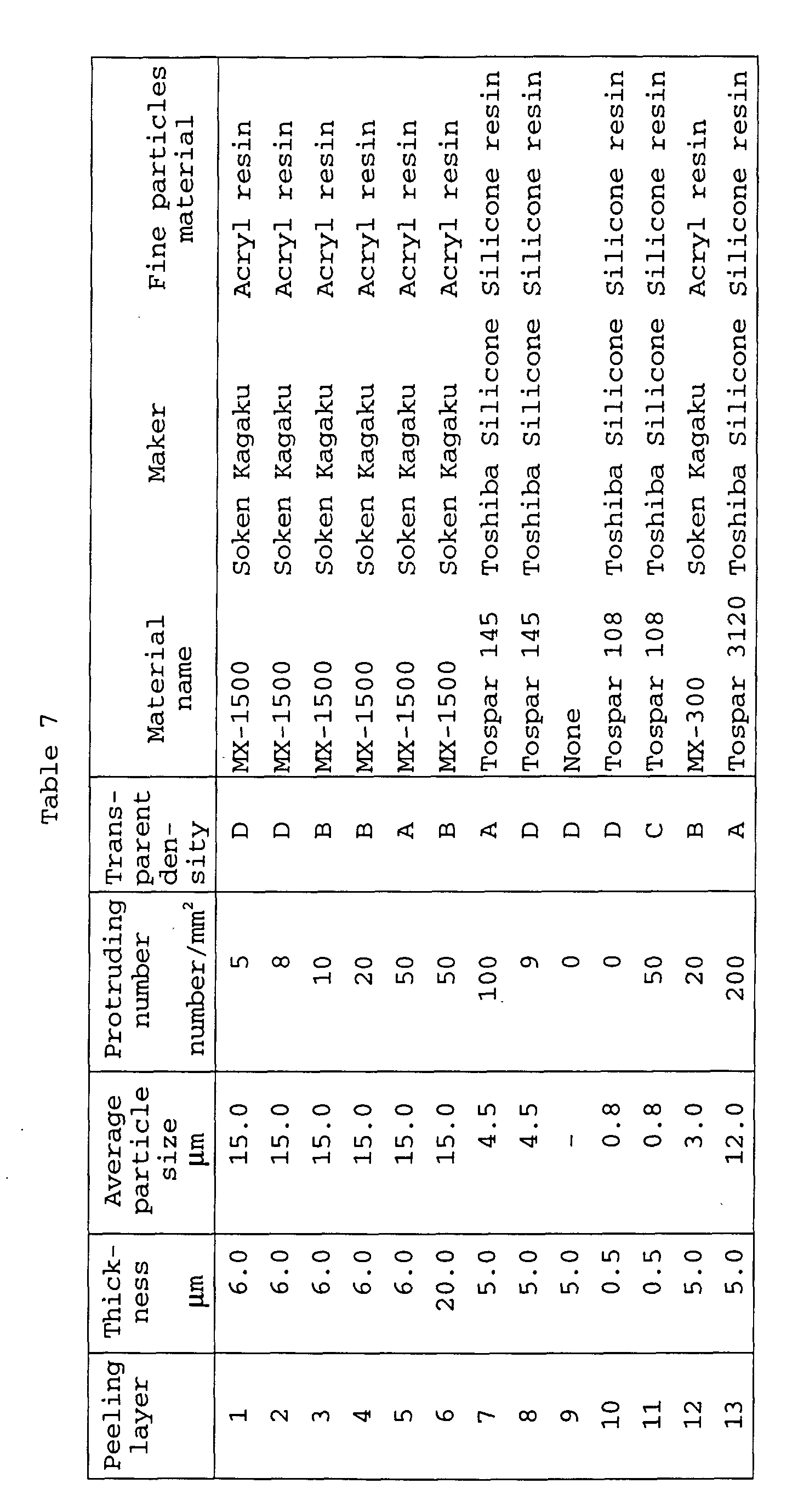
| Peeling layer | Ra | Transparent density | Resolving Power | |
| 20 | 0.016 | D | C | |
| 21 | 0.04 | B | A | |
| 22 | 0.10 | | A | |
| 23 | 0.50 | | A | |
| 24 | 1.00 | B | B | |
| 25 | 2.00 | D | D |
Claims (11)
- An image forming material comprising a support and provided thereon, a hardened image forming layer comprising a colourant having an absorption in the wavelength of from 300 to 800 nm, wherein a peeling layer is provided on the image forming layer and wherein the portion of the image forming layer exposed to a high density energy light radiation produces reduction of an adhesion force between the image forming layer and the support.
- The image forming material of any preceding claim, wherein the colourant is a light heat converting agent.
- The image forming material of claim 1, wherein the colourant is a metal atom-containing inorganic compound.
- The image forming material of any of claims 1 to 3, wherein the peeling layer comprises fine particles.
- The image forming material of claim 4, wherein the fine particles in the peeling layer protrude from the peeling layer surface, and the number of fine particles having a protruding height of from 1 to 20µm is 10 or more per mm2 of the peeling layer.
- The image forming material of any preceding claim, wherein the surface roughness Ra of the peeling layer surface facing the image forming layer is from 0.04 to 1.0µm, wherein Ra is measured according to JIS B0601.
- An image forming method comprisinga) imagewise exposing to a high density energy light an image forming material comprising a support and provided thereon, an image forming layer comprising a colorant having an absorption in the wavelength of from 300 to 800 nm, the image forming layer having been hardened, whereby adhesive force between the support and the exposed portions of the image forming layer is reduced;b) superposing an adhesive layer of an adhesive sheet on the exposed image forming layer; andc) separating the adhesive sheet from the image forming layer to transfer the exposed portions of the image forming layer to the adhesive layer.
- An image forming method comprisinga) imagewise exposing to a high density energy light an image forming material comprising a support and provided thereon, an image forming layer comprising a colorant having an absorption in the wavelength of from 300 to 800 nm, and a peeling layer in this order, the image forming layer having been hardened, whereby adhesive force between the support and the exposed portions of the image forming layer is reduced; andb) then separating the peeling layer from the image forming layer to transfer the exposed portions of the image forming layer to the peeling layer to form an image on the support.
- The image forming method of claim 7 or 8, wherein the imagewise exposing is carried out using a laser light.
- The image forming method of claim 9, wherein the laser light has a wavelength of from 600 to 1200 nm.
- The image forming method of any of claims 8 to 10, wherein the image forming layer of the image forming material has been subjected to calendar treatment.
Applications Claiming Priority (15)
| Application Number | Priority Date | Filing Date | Title |
|---|---|---|---|
| JP2947795 | 1995-02-17 | ||
| JP29477/95 | 1995-02-17 | ||
| JP2947795 | 1995-02-17 | ||
| JP81379/95 | 1995-04-06 | ||
| JP8137995 | 1995-04-06 | ||
| JP8137995 | 1995-04-06 | ||
| JP85488/95 | 1995-04-11 | ||
| JP8548895 | 1995-04-11 | ||
| JP8548895 | 1995-04-11 | ||
| JP105068/95 | 1995-04-28 | ||
| JP105071/95 | 1995-04-28 | ||
| JP10507195A JP3430382B2 (en) | 1995-04-11 | 1995-04-28 | Image forming material and image forming method using the same |
| JP10506895A JPH08334894A (en) | 1995-02-17 | 1995-04-28 | Image forming material and image forming method using the same |
| JP10507195 | 1995-04-28 | ||
| JP10506895 | 1995-04-28 |
Publications (2)
| Publication Number | Publication Date |
|---|---|
| EP0727321A1 EP0727321A1 (en) | 1996-08-21 |
| EP0727321B1 true EP0727321B1 (en) | 2001-05-09 |
Family
ID=27521143
Family Applications (1)
| Application Number | Title | Priority Date | Filing Date |
|---|---|---|---|
| EP96301042A Expired - Lifetime EP0727321B1 (en) | 1995-02-17 | 1996-02-15 | Image forming material, method of preparing the same and image forming method employing the same |
Country Status (3)
| Country | Link |
|---|---|
| US (1) | US5691103A (en) |
| EP (1) | EP0727321B1 (en) |
| DE (1) | DE69612684D1 (en) |
Cited By (1)
| Publication number | Priority date | Publication date | Assignee | Title |
|---|---|---|---|---|
| US20160270236A1 (en) * | 2013-10-30 | 2016-09-15 | Nederlandse Organisatie Voor Toegepast- Natuurwetenschappelijk Onderzoek Tno | Substrate comprising an electrical circuit pattern, method and system for providing same |
Families Citing this family (18)
| Publication number | Priority date | Publication date | Assignee | Title |
|---|---|---|---|---|
| EP0794067B1 (en) * | 1996-03-07 | 1999-07-28 | Konica Corporation | Image forming material and image forming method employing the same |
| JPH1052980A (en) * | 1996-08-09 | 1998-02-24 | Konica Corp | Image forming material and image forming method using the material |
| JPH10148939A (en) * | 1996-11-18 | 1998-06-02 | Konica Corp | Image forming material and its production |
| US6051355A (en) * | 1997-08-01 | 2000-04-18 | Agfa-Gevaert, N. V. | Receptor element for non-impact printing comprising an image receiving layer with a polymer comprising sulphonic acid groups |
| WO1999028890A1 (en) * | 1997-11-29 | 1999-06-10 | Koninklijke Philips Electronics N.V. | Display device comprising a light guide |
| JP3119230B2 (en) * | 1998-03-03 | 2000-12-18 | 日本電気株式会社 | Resin film and method for connecting electronic components using the same |
| US6190831B1 (en) * | 1998-09-29 | 2001-02-20 | Kodak Polychrome Graphics Llc | Processless direct write printing plate having heat sensitive positively-charged polymers and methods of imaging and printing |
| JP2000181070A (en) * | 1998-12-14 | 2000-06-30 | Konica Corp | Ablation type image forming material and method for producing the same |
| US6203952B1 (en) | 1999-01-14 | 2001-03-20 | 3M Innovative Properties Company | Imaged article on polymeric substrate |
| US6399268B1 (en) * | 1999-04-16 | 2002-06-04 | Kodak Polychrome Graphics Llc | Processless direct write imaging member containing polymer grafted carbon and methods of imaging and printing |
| DE19937478B4 (en) | 1999-08-07 | 2004-08-19 | Man Roland Druckmaschinen Ag | Thermal transfer film for laser-induced coating of a metal surface |
| US6361923B1 (en) * | 1999-08-17 | 2002-03-26 | International Business Machines Corporation | Laser ablatable material and its use |
| US6410202B1 (en) * | 1999-08-31 | 2002-06-25 | Eastman Kodak Company | Thermal switchable composition and imaging member containing cationic IR dye and methods of imaging and printing |
| DE10045774C2 (en) * | 2000-09-15 | 2002-08-14 | Roland Man Druckmasch | Thermal transfer film with reactive polymer mass for laser-induced coating, its production and use |
| US6787063B2 (en) * | 2001-03-12 | 2004-09-07 | Seiko Epson Corporation | Compositions, methods for producing films, functional elements, methods for producing functional elements, methods for producing electro-optical devices and methods for producing electronic apparatus |
| WO2003050788A1 (en) * | 2001-12-10 | 2003-06-19 | Koninklijke Philips Electronics N.V. | Display panel comprising a light guide |
| US6841320B2 (en) * | 2002-02-06 | 2005-01-11 | Optiva, Inc. | Method of fabricating anisotropic crystal film on a receptor plate via transfer from the donor plate, the donor plate and the method of its fabrication |
| AU2003249552A1 (en) * | 2002-08-07 | 2004-02-25 | Vim Technologies Ltd. | Lithographic printing members and a method and a system for preparation of lithographic printing members |
Family Cites Families (6)
| Publication number | Priority date | Publication date | Assignee | Title |
|---|---|---|---|---|
| US3964389A (en) * | 1974-01-17 | 1976-06-22 | Scott Paper Company | Printing plate by laser transfer |
| GB8410515D0 (en) * | 1984-04-25 | 1984-05-31 | Ici Plc | Laser-imageable assembly |
| WO1993003928A1 (en) * | 1991-08-16 | 1993-03-04 | E.I. Du Pont De Nemours And Company | Infra-red direct write imaging media |
| EP0685333A2 (en) * | 1992-06-05 | 1995-12-06 | Agfa-Gevaert N.V. | A heat mode recording material and method for producing driographic printing plates |
| US5278023A (en) * | 1992-11-16 | 1994-01-11 | Minnesota Mining And Manufacturing Company | Propellant-containing thermal transfer donor elements |
| JP2592225B2 (en) * | 1993-02-09 | 1997-03-19 | アグフア−ゲヴエルト・ナームローゼ・フエンノートシヤツプ | Heat mode recording material and method for producing lithographic printing plate using the same |
-
1996
- 1996-02-09 US US08/599,186 patent/US5691103A/en not_active Expired - Fee Related
- 1996-02-15 EP EP96301042A patent/EP0727321B1/en not_active Expired - Lifetime
- 1996-02-15 DE DE69612684T patent/DE69612684D1/en not_active Expired - Lifetime
Cited By (2)
| Publication number | Priority date | Publication date | Assignee | Title |
|---|---|---|---|---|
| US20160270236A1 (en) * | 2013-10-30 | 2016-09-15 | Nederlandse Organisatie Voor Toegepast- Natuurwetenschappelijk Onderzoek Tno | Substrate comprising an electrical circuit pattern, method and system for providing same |
| US10349525B2 (en) * | 2013-10-30 | 2019-07-09 | Nederlandse Organisatie Voor Toegepast-Natuurwetenschappelijk Onderzoek Tno | Substrate comprising an electrical circuit pattern, method and system for providing same |
Also Published As
| Publication number | Publication date |
|---|---|
| EP0727321A1 (en) | 1996-08-21 |
| DE69612684D1 (en) | 2001-06-13 |
| US5691103A (en) | 1997-11-25 |
Similar Documents
| Publication | Publication Date | Title |
|---|---|---|
| US5691103A (en) | Image forming material, method of preparing the same and image forming method employing the same | |
| EP0727322B1 (en) | Image forming material, method of preparing the same and image forming method employing the same | |
| US5856060A (en) | Image forming material and image forming method employing the same | |
| EP0823334B1 (en) | Image forming material and image forming method employing the same | |
| US6455206B1 (en) | Image forming method, image forming apparatus and image recording material | |
| US6344303B1 (en) | Image forming material and preparation method thereof | |
| EP0842788B1 (en) | Image-forming material with protective layer and its preparation method | |
| JPH11102076A (en) | Ablation type image forming material and image forming method using the same | |
| JPH08334894A (en) | Image forming material and image forming method using the same | |
| JPH08337054A (en) | Image forming material and image forming method employing said material | |
| JPH08337053A (en) | Image forming material and image forming method as well as image recording body, which are employing said material | |
| JP2000052655A (en) | Image forming material and image forming method using the same | |
| JPH0915849A (en) | Image forming material, its forming method, and image forming method using it | |
| US6368767B1 (en) | Image forming material and production method of the same, and an image forming apparatus | |
| JP2000127622A (en) | Image forming material, its production, and image forming method using the same | |
| JP3674268B2 (en) | LASER EXPOSURE APPARATUS, RECORDING METHOD AND SHEET-LIKE MATERIAL USED FOR THE SAME | |
| JP2000258900A (en) | Image forming material | |
| JPH08310124A (en) | Image forming material | |
| EP0842789A1 (en) | Thermal image forming method using light | |
| JPH08337056A (en) | Image forming material and image forming method employing said material | |
| JPH1178265A (en) | Image forming material and method for forming image | |
| JP2000255167A (en) | Image forming material and image forming method | |
| JP2000006521A (en) | Ablation type image forming material and image forming method using the same | |
| JPH10333333A (en) | Image forming material and image forming method using the same | |
| JP2004188890A (en) | Original plate for lithographic printing and printing method using the same |
Legal Events
| Date | Code | Title | Description |
|---|---|---|---|
| PUAI | Public reference made under article 153(3) epc to a published international application that has entered the european phase |
Free format text: ORIGINAL CODE: 0009012 |
|
| AK | Designated contracting states |
Kind code of ref document: A1 Designated state(s): DE FR GB NL |
|
| 17P | Request for examination filed |
Effective date: 19970109 |
|
| 17Q | First examination report despatched |
Effective date: 19980331 |
|
| GRAG | Despatch of communication of intention to grant |
Free format text: ORIGINAL CODE: EPIDOS AGRA |
|
| GRAG | Despatch of communication of intention to grant |
Free format text: ORIGINAL CODE: EPIDOS AGRA |
|
| GRAH | Despatch of communication of intention to grant a patent |
Free format text: ORIGINAL CODE: EPIDOS IGRA |
|
| GRAH | Despatch of communication of intention to grant a patent |
Free format text: ORIGINAL CODE: EPIDOS IGRA |
|
| GRAA | (expected) grant |
Free format text: ORIGINAL CODE: 0009210 |
|
| AK | Designated contracting states |
Kind code of ref document: B1 Designated state(s): DE FR GB NL |
|
| PG25 | Lapsed in a contracting state [announced via postgrant information from national office to epo] |
Ref country code: NL Free format text: LAPSE BECAUSE OF FAILURE TO SUBMIT A TRANSLATION OF THE DESCRIPTION OR TO PAY THE FEE WITHIN THE PRESCRIBED TIME-LIMIT Effective date: 20010509 Ref country code: FR Free format text: LAPSE BECAUSE OF FAILURE TO SUBMIT A TRANSLATION OF THE DESCRIPTION OR TO PAY THE FEE WITHIN THE PRESCRIBED TIME-LIMIT Effective date: 20010509 |
|
| REF | Corresponds to: |
Ref document number: 69612684 Country of ref document: DE Date of ref document: 20010613 |
|
| PG25 | Lapsed in a contracting state [announced via postgrant information from national office to epo] |
Ref country code: DE Free format text: LAPSE BECAUSE OF FAILURE TO SUBMIT A TRANSLATION OF THE DESCRIPTION OR TO PAY THE FEE WITHIN THE PRESCRIBED TIME-LIMIT Effective date: 20010810 |
|
| NLV1 | Nl: lapsed or annulled due to failure to fulfill the requirements of art. 29p and 29m of the patents act | ||
| EN | Fr: translation not filed | ||
| REG | Reference to a national code |
Ref country code: GB Ref legal event code: IF02 |
|
| PLBE | No opposition filed within time limit |
Free format text: ORIGINAL CODE: 0009261 |
|
| STAA | Information on the status of an ep patent application or granted ep patent |
Free format text: STATUS: NO OPPOSITION FILED WITHIN TIME LIMIT |
|
| 26N | No opposition filed | ||
| PGFP | Annual fee paid to national office [announced via postgrant information from national office to epo] |
Ref country code: GB Payment date: 20030212 Year of fee payment: 8 |
|
| PG25 | Lapsed in a contracting state [announced via postgrant information from national office to epo] |
Ref country code: GB Free format text: LAPSE BECAUSE OF NON-PAYMENT OF DUE FEES Effective date: 20040215 |
|
| GBPC | Gb: european patent ceased through non-payment of renewal fee |
Effective date: 20040215 |