EP0726816B1 - Screening apparatus - Google Patents
Screening apparatus Download PDFInfo
- Publication number
- EP0726816B1 EP0726816B1 EP93914516A EP93914516A EP0726816B1 EP 0726816 B1 EP0726816 B1 EP 0726816B1 EP 93914516 A EP93914516 A EP 93914516A EP 93914516 A EP93914516 A EP 93914516A EP 0726816 B1 EP0726816 B1 EP 0726816B1
- Authority
- EP
- European Patent Office
- Prior art keywords
- station
- surround
- bar member
- outer end
- screening
- Prior art date
- Legal status (The legal status is an assumption and is not a legal conclusion. Google has not performed a legal analysis and makes no representation as to the accuracy of the status listed.)
- Expired - Lifetime
Links
- 238000012216 screening Methods 0.000 title claims abstract description 32
- 230000035939 shock Effects 0.000 claims abstract description 4
- 239000000463 material Substances 0.000 description 6
- 230000003534 oscillatory effect Effects 0.000 description 2
- 238000007873 sieving Methods 0.000 description 2
- 239000012530 fluid Substances 0.000 description 1
- 238000012986 modification Methods 0.000 description 1
- 230000004048 modification Effects 0.000 description 1
Images

Classifications
-
- B—PERFORMING OPERATIONS; TRANSPORTING
- B07—SEPARATING SOLIDS FROM SOLIDS; SORTING
- B07B—SEPARATING SOLIDS FROM SOLIDS BY SIEVING, SCREENING, SIFTING OR BY USING GAS CURRENTS; SEPARATING BY OTHER DRY METHODS APPLICABLE TO BULK MATERIAL, e.g. LOOSE ARTICLES FIT TO BE HANDLED LIKE BULK MATERIAL
- B07B1/00—Sieving, screening, sifting, or sorting solid materials using networks, gratings, grids, or the like
- B07B1/46—Constructional details of screens in general; Cleaning or heating of screens
- B07B1/48—Stretching devices for screens
Definitions
- This invention relates to screening apparatus for use in size classifying discrete material.
- screening apparatus has been provided of the type having a screen box with an upstanding surround within which one or more vertically-spaced stations have been provided each to horizontally carry an elongate screening surface.
- the action of size classifying material passed into the screen box is effected by vibratory, reciprocatory, or oscillatory means.
- the or each screening surface has engaging means at longitudinally opposite ends each to be secured to a holding member arranged transversely, one at each longitudinally opposite ends of the station.
- a holding member is fixed and the other holding member is movably adjustable to allow longitudinal tensioning or releasing of a respective screening surface.
- Replacing worn screening surfaces or changing screening surfaces to give a different grade(s) of material on existing screening apparatus of the above type is time consuming particularly, but not only, in the tensioning aspect of the replacement screening surfaces and this is disadvantageous.
- US-A-4655907 describes a tensioning apparatus for a wire net in a vibration sieving machine.
- the ends of the net are secured to a fixed holder and a moveable holder biased apart by a spring.
- a hydraulic device mounted on the frame of the machine acts against the spring to relax the tension in the net.
- the hydraulic device is permanently mounted on the frame of the machine and is therefore subjected to all movements of the sieving machine, especially the constant vibration.
- An object of the present invention is to obviate or mitigate the above disadvantages.
- the present invention is a screening apparatus comprising a rectangular screen box supported through a plurality of shock absorbing members from an elongate mounting frame, the screen box having an upstanding wall surround around at least three sides thereof and within which one or more vertically-spaced stations are provided, the or each station being to carry an elongate screening surface having engaging means at each longitudinal end thereof, each engaging means to be secured to a respective holding bar member arranged transversely between opposite sides of the surround and at or near opposite ends of each station, the outer ends of one or both bar members for each station extending out through an opening in opposite sides of the surround to be engagable by means to move the bar members for each station relatively apart to longitudinally tension a screening surface secured thereto, the moving means being transferable between out-of-use and in-use positions, and the moving means for each outer end of the or each bar member being powered length-extension means carried in the out-of-use position on respective components of the frame laterally of each opposed side of the surround and mounted in the in-use position on the respective opposed
- the length-extension means are hydraulically or pneumatically operable ram and cylinder arrangements.
- the outer end of the cylinder of each arrangement is desirably provided with an apertured lug and the outer end of the ram of each arrangement is desirably provided with a cup.
- fixing means are provided to secure each end of a bar when the respective arrangements are in their extended positions.
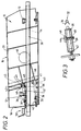
- a screening apparatus comprises a rectangular screen box 10 supported through a plurality of shock absorbing members 12 from an elongate rectangular mounting frame 14.
- the screen box 10 has an upstanding wall surround 16 around at least three sides thereof, ie. one end 18 and two opposed sides 20, and within the area defined by said sides one or more vertically-spaced stations 22 (two are shown in this embodiment) are provided.
- Each station 22 is to carry an elongate screening surface 24 having engaging means at each longitudinal end thereof.
- Each screening surface masks the area defined by the three sides.
- Each engaging means is in the form of a reflexive bent portion 26 which is to be secured to, ie. hooked over, a respective holding bar member 28 arranged transversely between opposite sides 20 of the surround 16 and at or near opposite ends of each station 22.
- the outer ends of one or both bar members 28 for each station 22 extend out through an opening 30 in opposite sides 20 of the surround 16.
- only one bar member 28, ie. that nearer the end 18, is movable and extends through openings 30.
- the other bar member 28 is fixed to the sides 20.
- the outer ends of the movable bar member 28 for each station are each to be engagable by means to move the bar member 28 relatively apart from the fixed bar member 28 to longitudinally tension a screening surface 24 secured thereto.
- the moving means for each outer end of each movable bar member 28 is a powered length-extension means.
- the length-extension means are hydraulically or pneumatically operable ram and cylinder arrangements 32.
- the outer end of the cylinder of each arrangement 32 is provided with an apertured lug 34 and the outer end of the ram of each arrangement 32 is provided with a cup 36.
- the arrangements 32 are carried in an out-of-use position on respective longitudinal components 38 of the frame 14 laterally of each opposed side 20 of the surround 16.
- Each arrangement 32 is transferable for mounting to an in-use position on the respective opposed side 20 of the surround 16 between an anchorage 40 and the respective outer end of the movable bar member 28.
- Each anchorage 40 comprises two parallel cheeks 41 outstanding from the respective side 20, the cheeks being spaced apart vertically to receive the corresponding lug 34, there being an aligned hole 45 in the cheeks 41 positioned for the aperture in the lug 34 to be aligned therewith and a pin 43 insertable therein to secure the cheeks 41 and lug 34 together.
- Power means to actuate said moving means comprising a hydraulic fluid supply (not shown) and a hydraulic pump (not shown) connected up to the arrangements 32 by hosing (omitted for clarity) through a control valve mechanism 50.
- the power means is a pressurised air supply fed through hosing to the arrangements 32 with a control valve mechanism interposed in the hosing circuit.
- Fixing means are provided to secure each outer end of the movable bar member 28 when the respective arrangements 32 are in their extended positions.
- the fixing means comprises a collar 42 outstanding from around each opening 30, the collars 42 each having two straight portions, a top and a bottom, in which one or more aligned apertures 48 are provided to be engaged by a bolt or pin 44 on the inner side of the respective outer end of the movable bar member 28 when extended.
- the screening apparatus is mounted on a machine or structure via the frame 14 to receive discrete material.
- the action of size classifying material fed into the screen box 10 is achieved by vibratory, reciprocatory or oscillatory means shown generally at 46.
- the arrangements 32 are stored in their out-of-use position on components 38 so that they are not affected by movement of the screen box 10 due to the means 46.
- the arrangements 32 for each station are moved into their in-use position and each is secured by the respective pin 43 passing through the corresponding aligned apertures in lug 34 and cheeks 41, and with the cup 36 positioned to engage the respective outer end of movable bar member 28.
- the rams of the arrangements 32 are extended for the cups 36 to engage their respective outer end of movable bar member 28.
- the respective pins 44 are removed and the rams retracted.
- the screening surface 24 is removed and the new screening surface located over the bar members 28.
- the rams are again extended and the pins 44 located.
- the rams are then retracted, the pins 43 removed and the arrangements 32 moved to their respective out-of-use positions.
Landscapes
- Combined Means For Separation Of Solids (AREA)
- Measuring Or Testing Involving Enzymes Or Micro-Organisms (AREA)
- Cartons (AREA)
- Investigating Or Analysing Biological Materials (AREA)
- Magnetic Resonance Imaging Apparatus (AREA)
- Massaging Devices (AREA)
- Eye Examination Apparatus (AREA)
- Investigating Strength Of Materials By Application Of Mechanical Stress (AREA)
Abstract
Description
Claims (5)
- A screening apparatus comprising a rectangular screen box (10) supported through a plurality of shock absorbing members (12) from an elongate mounting frame (14), the screen box (10) having an upstanding wall surround (16) around at least three sides thereof and within which one or more vertically-spaced stations (22) are provided, the or each station (22) being to carry an elongate screening surface (24) having engaging means at each longitudinal end thereof, each engaging means to be secured to a respective holding bar member (28) arranged transversely between opposite sides (20) of the surround (16) and at or near opposite ends of each station (22), the outer ends of one or both bar members (28) for each station (22) extending out through an opening (30) in opposite sides (20) of the surround (16) to be engagable by means to move the bar members (28) for each station (22) relatively apart to longitudinally tension a screening surface (24) secured thereto, the moving means being transferable between out-of-use and in-use positions, and the moving means for each outer end of the or each bar member (28) being powered length-extension means carried in the out-of-use position on respective components (38) of the frame (14) laterally of each opposed side (20) of the surround (16) and mounted in the in-use position on the respective opposed side (20) of the surround (16) between an anchorage (40) and the respective outer end of the bar member (28), and power means to actuate said moving means.
- A screening apparatus as claimed in Claim 1, wherein the length-extension means are hydraulically or pneumatically operable ram and cylinder arrangements (32).
- A screening apparatus as claimed in Claim 2, wherein the outer end of the cylinder of each arrangement (32) is provided with an apertured lug (34) and the outer end of the ram of each arrangement (32) is provided with a cup (36).
- A screening apparatus as claimed in Claim 2 or 3, wherein fixing means are provided to secure each end of the bar (28) when the respective arrangements (32) are in their extended positions.
- A screening apparatus as claimed in Claim 4, wherein the fixing means comprises a collar (42) outstanding from around each opening (30), the collars (42) each having two vertically spaced portions in which one or more aligned apertures (48) are provided to be engaged by a bolt when a respective outer end of the movable bar member (28) has been extended therebeyond.
Applications Claiming Priority (3)
| Application Number | Priority Date | Filing Date | Title |
|---|---|---|---|
| GB9202216 | 1992-02-03 | ||
| GB929202216A GB9202216D0 (en) | 1992-02-03 | 1992-02-03 | Improvements in or relating to screening apparatus |
| PCT/GB1993/000227 WO1993014883A1 (en) | 1992-02-03 | 1993-02-03 | Improvements in or relating to screening apparatus |
Publications (2)
| Publication Number | Publication Date |
|---|---|
| EP0726816A1 EP0726816A1 (en) | 1996-08-21 |
| EP0726816B1 true EP0726816B1 (en) | 1998-01-14 |
Family
ID=10709709
Family Applications (1)
| Application Number | Title | Priority Date | Filing Date |
|---|---|---|---|
| EP93914516A Expired - Lifetime EP0726816B1 (en) | 1992-02-03 | 1993-02-03 | Screening apparatus |
Country Status (6)
| Country | Link |
|---|---|
| US (1) | US5513756A (en) |
| EP (1) | EP0726816B1 (en) |
| AT (1) | ATE162116T1 (en) |
| DE (1) | DE69316396D1 (en) |
| GB (2) | GB9202216D0 (en) |
| WO (1) | WO1993014883A1 (en) |
Families Citing this family (1)
| Publication number | Priority date | Publication date | Assignee | Title |
|---|---|---|---|---|
| US7918346B2 (en) | 2008-05-31 | 2011-04-05 | Mark Roppo | Vibrating screen tensioning apparatus and method |
Family Cites Families (12)
| Publication number | Priority date | Publication date | Assignee | Title |
|---|---|---|---|---|
| BE549969A (en) * | ||||
| CH343212A (en) * | 1956-09-25 | 1959-12-15 | Von Roll Ag | Sieve with clamping device for classifying and sorting machines |
| AT262911B (en) * | 1966-08-19 | 1968-07-10 | Binder Co Ag | Device for tensioning and fixing a sieve on a sieve frame |
| US3655045A (en) * | 1969-10-30 | 1972-04-11 | Ajax Flexible Coupling Co Inc | Method and apparatus for conveying and separating materials |
| DK667974A (en) * | 1974-01-26 | 1975-09-15 | Powerscreen Int Ltd | |
| AT329474B (en) * | 1974-02-25 | 1976-05-10 | Oesterr Amerikan Magnesit | CLAMPING DEVICE FOR SCREEN BOTTOM |
| DE2938684A1 (en) * | 1979-09-25 | 1981-04-09 | Krauss-Maffei AG, 8000 München | Filter cloths in centrifuge bowl - tensioned by rings contoured to fit inner profile of bowl |
| US4319992A (en) * | 1980-10-28 | 1982-03-16 | Midwestern Industries, Inc. | Material separating machine |
| US4420391A (en) * | 1981-10-13 | 1983-12-13 | Dresser Industries, Inc. | Screen tensioning arrangement |
| JPS6133679U (en) * | 1984-07-31 | 1986-02-28 | 株式会社 安藤スクリ−ン製作所 | Sieve mesh tensioning device in vibrating sieve machine |
| IT1188446B (en) * | 1986-03-17 | 1988-01-14 | Poli Srl Flli De | SIMPLE OR MULTIPLE TYPE VIBRATION SCREEN |
| DE8902982U1 (en) * | 1989-03-10 | 1989-05-18 | Rhewum GmbH, 5630 Remscheid | Device for cleaning the screen fabric of screening machines |
-
1992
- 1992-02-03 GB GB929202216A patent/GB9202216D0/en active Pending
-
1993
- 1993-02-03 DE DE69316396T patent/DE69316396D1/en not_active Expired - Lifetime
- 1993-02-03 WO PCT/GB1993/000227 patent/WO1993014883A1/en not_active Ceased
- 1993-02-03 EP EP93914516A patent/EP0726816B1/en not_active Expired - Lifetime
- 1993-02-03 GB GB9415611A patent/GB2279891B/en not_active Expired - Fee Related
- 1993-02-03 AT AT93914516T patent/ATE162116T1/en not_active IP Right Cessation
-
1994
- 1994-08-02 US US08/284,428 patent/US5513756A/en not_active Expired - Fee Related
Also Published As
| Publication number | Publication date |
|---|---|
| WO1993014883A1 (en) | 1993-08-05 |
| GB2279891A (en) | 1995-01-18 |
| GB9202216D0 (en) | 1992-03-18 |
| EP0726816A1 (en) | 1996-08-21 |
| GB9415611D0 (en) | 1994-09-28 |
| DE69316396D1 (en) | 1998-02-19 |
| US5513756A (en) | 1996-05-07 |
| ATE162116T1 (en) | 1998-01-15 |
| GB2279891B (en) | 1995-06-07 |
Similar Documents
| Publication | Publication Date | Title |
|---|---|---|
| DE4019884C2 (en) | ||
| US4040951A (en) | Apparatus for retaining and readily releasing a shaker screen | |
| ES2169177T3 (en) | EQUIPMENT FOR THE SEPARATION OF PATTERNS IN THE BREAST OF A MACHINE OF CUTTING ELEMENTS IN PLATE. | |
| DE102015122314B3 (en) | linear friction | |
| GB2221406A (en) | Vibratory screening machine | |
| DE4326146A1 (en) | Vibration linear conveyor | |
| DE4433876C2 (en) | Weft brake for a defenseless weaving machine | |
| US5513756A (en) | Screening apparatus having a screen tensioning device | |
| EP0511334B1 (en) | Solder or conductive paste printing device | |
| DE10312706B4 (en) | A linear vibratory conveyor | |
| CA1275975C (en) | Method and apparatus for cleaning of screen-cloths in particular at vibrating screening equipment | |
| US3655045A (en) | Method and apparatus for conveying and separating materials | |
| EP0124763B1 (en) | Device for forcibly inserting furniture mountings | |
| EP0028792A2 (en) | Multi-deck screening machine | |
| DE3738350A1 (en) | CONCRETE CASTING MACHINE | |
| DE3133342C2 (en) | ||
| US1864940A (en) | Apparatus for screening materials | |
| US2667773A (en) | Warp tensioning bar for knitting machines | |
| EP0925877B1 (en) | Clamping device | |
| DE1610832C3 (en) | Machine for attaching holding elements | |
| DE9200239U1 (en) | Device for welding workpieces made of thermoplastic | |
| DE3330196C1 (en) | Sieving machine | |
| DE3415496C1 (en) | Sieving machine | |
| WO1990004466A1 (en) | Screening device for particulate material | |
| EP0508211A1 (en) | Apparatus for holding and guiding material in embroidering machines |
Legal Events
| Date | Code | Title | Description |
|---|---|---|---|
| PUAI | Public reference made under article 153(3) epc to a published international application that has entered the european phase |
Free format text: ORIGINAL CODE: 0009012 |
|
| 17P | Request for examination filed |
Effective date: 19940806 |
|
| AK | Designated contracting states |
Kind code of ref document: A1 Designated state(s): AT DE ES FR IT |
|
| 17Q | First examination report despatched |
Effective date: 19960905 |
|
| GRAG | Despatch of communication of intention to grant |
Free format text: ORIGINAL CODE: EPIDOS AGRA |
|
| GRAG | Despatch of communication of intention to grant |
Free format text: ORIGINAL CODE: EPIDOS AGRA |
|
| GRAG | Despatch of communication of intention to grant |
Free format text: ORIGINAL CODE: EPIDOS AGRA |
|
| GRAH | Despatch of communication of intention to grant a patent |
Free format text: ORIGINAL CODE: EPIDOS IGRA |
|
| GRAH | Despatch of communication of intention to grant a patent |
Free format text: ORIGINAL CODE: EPIDOS IGRA |
|
| GRAA | (expected) grant |
Free format text: ORIGINAL CODE: 0009210 |
|
| AK | Designated contracting states |
Kind code of ref document: B1 Designated state(s): AT DE ES FR IT |
|
| PG25 | Lapsed in a contracting state [announced via postgrant information from national office to epo] |
Ref country code: IT Free format text: LAPSE BECAUSE OF FAILURE TO SUBMIT A TRANSLATION OF THE DESCRIPTION OR TO PAY THE FEE WITHIN THE PRE;WARNING: LAPSES OF ITALIAN PATENTS WITH EFFECTIVE DATE BEFORE 2007 MAY HAVE OCCURRED AT ANY TIME BEFORE 2007. THE CORRECT EFFECTIVE DATE MAY BE DIFFERENT FROM THE ONE RECORDED.SCRIBED TIME-LIMIT Effective date: 19980114 Ref country code: FR Free format text: LAPSE BECAUSE OF FAILURE TO SUBMIT A TRANSLATION OF THE DESCRIPTION OR TO PAY THE FEE WITHIN THE PRESCRIBED TIME-LIMIT Effective date: 19980114 Ref country code: ES Free format text: THE PATENT HAS BEEN ANNULLED BY A DECISION OF A NATIONAL AUTHORITY Effective date: 19980114 Ref country code: AT Free format text: LAPSE BECAUSE OF FAILURE TO SUBMIT A TRANSLATION OF THE DESCRIPTION OR TO PAY THE FEE WITHIN THE PRESCRIBED TIME-LIMIT Effective date: 19980114 |
|
| REF | Corresponds to: |
Ref document number: 162116 Country of ref document: AT Date of ref document: 19980115 Kind code of ref document: T |
|
| REF | Corresponds to: |
Ref document number: 69316396 Country of ref document: DE Date of ref document: 19980219 |
|
| PG25 | Lapsed in a contracting state [announced via postgrant information from national office to epo] |
Ref country code: DE Free format text: LAPSE BECAUSE OF FAILURE TO SUBMIT A TRANSLATION OF THE DESCRIPTION OR TO PAY THE FEE WITHIN THE PRESCRIBED TIME-LIMIT Effective date: 19980415 |
|
| EN | Fr: translation not filed | ||
| PLBE | No opposition filed within time limit |
Free format text: ORIGINAL CODE: 0009261 |
|
| STAA | Information on the status of an ep patent application or granted ep patent |
Free format text: STATUS: NO OPPOSITION FILED WITHIN TIME LIMIT |
|
| 26N | No opposition filed |