EP0726479B1 - Kippspiegelanordnung - Google Patents
Kippspiegelanordnung Download PDFInfo
- Publication number
- EP0726479B1 EP0726479B1 EP96100889A EP96100889A EP0726479B1 EP 0726479 B1 EP0726479 B1 EP 0726479B1 EP 96100889 A EP96100889 A EP 96100889A EP 96100889 A EP96100889 A EP 96100889A EP 0726479 B1 EP0726479 B1 EP 0726479B1
- Authority
- EP
- European Patent Office
- Prior art keywords
- tilting mirror
- mirror
- tilting
- base body
- arrangement according
- Prior art date
- Legal status (The legal status is an assumption and is not a legal conclusion. Google has not performed a legal analysis and makes no representation as to the accuracy of the status listed.)
- Expired - Lifetime
Links
Images



Classifications
-
- G—PHYSICS
- G02—OPTICS
- G02B—OPTICAL ELEMENTS, SYSTEMS OR APPARATUS
- G02B7/00—Mountings, adjusting means, or light-tight connections, for optical elements
- G02B7/18—Mountings, adjusting means, or light-tight connections, for optical elements for prisms; for mirrors
- G02B7/182—Mountings, adjusting means, or light-tight connections, for optical elements for prisms; for mirrors for mirrors
- G02B7/1821—Mountings, adjusting means, or light-tight connections, for optical elements for prisms; for mirrors for mirrors for rotating or oscillating mirrors
Definitions
- the invention relates to a tilting mirror arrangement, which at least one tilt mirror, a base body and at least a mirror bearing with a fixed pivot point between the tilting mirror and the base body.
- tilting mirror arrangements are known from the prior art well known in the art. They serve one on them striking light beam defined by a certain angle distract. One differentiates in particular 1-axis and 2-axis tilting mirror.
- a tilting mirror arrangement is known from US Pat. No. 4,708,420, which is used for scanning.
- the scan mirror via flexible joints with piezoceramic drive elements connected, which is arranged parallel to the mirror surface are. So that the piezoceramic drive elements around the mirror can tilt a large angle, this arrangement must be very large his. This results from the slight bending of the Piezoceramic drive elements, which are proportional to the length of these elements is. This arrangement is therefore not suitable for this small mirrors to tilt over a wide range of angles if the Drive mechanism behind the tilting mirror to the dimension of the Mirror surface should be limited.
- a tilting mirror arrangement is known from US Pat. No. 4,383,763, at which the mirror is mounted on a tipping point and over piezoelectric ceramics is moved.
- too Dimensions of the mirror can be very large when the tilting mirror is around should be tilted at least 1 °.
- a tilting mirror holder is known from US Pat. No. 4,660,941 which the tilting mirror movement by piezoelectric elements is reached and the piezoelectric elements act Lever on the mirror. This arrangement is not for this either suitable to tilt a small mirror by at least 1 °.
- a piezoelectric beam reflector is known from US Pat. No. 4,691,212 known which is used in a scanning arrangement.
- the disadvantage of this arrangement is that a certain deflection angle cannot be held rigidly when the pivot point is fixed should.
- the US 4,613,203 shows a tilting mirror that over a Cross spring joint can be tilted in one axis on a base body is stored.
- the tilting mirror is used by several Base body attached electromagnets powered with corresponding ferromagnetic anchors attached to the tilting mirror interact.
- the SU 949 618 shows a movable mirror that has three Piezo actuators can be driven.
- the piezo actuators act spherically on extensions trained ring, which is attached below the mirror.
- the Extensions also serve to store the mirror. The mirror therefore does not have an almost fixed pivot point the base body.
- EP-A-0 154 870 describes a light deflecting device with a tiltable part supported by point support, which has a reflective mirror surface on its top.
- the installation position of the arrangement in the room should be arbitrary.
- the particular advantage of the invention is that the invention Tilting mirror has a construction in which it load-bearing base body is not larger than the mirror surface.
- the tilt angle ⁇ can still be relatively large ( ⁇ > 0.5 °).
- the tilt angle ⁇ is advantageously in the Range between 1 ° ⁇ ⁇ 5 °.
- the mirror bearing should also be low-friction, so that the tilting mirror can be easily adjusted and easily moved from one position to another desired position can be.
- the invention allows the construction of a tilting mirror assembly, the Mirror diagonal and base diagonal is less than 4 cm. It is also possible to have a tilt angle ⁇ greater than 0.5 ° to be realized (even 5-10 ° tilt angles are possible even with sizes less than 10 mm edge length realizable with the invention).
- this retaining device is a spring designed.
- the tilting mirror arrangement When the tilting mirror arrangement is inclined in the room forces act on the tilting mirror, depending on the angle of inclination the tilting mirror arrangement from its basic position move. Do you know the inclination of the tilt mirror assembly during the use of the tilt mirror, it is advantageous for at least one predetermined preferred inclined position of the tilting mirror arrangement a weight compensation device for the Attach tilt mirror or let it attack.
- At least one point or surface should be on the Extension to be oriented perpendicular to the tilt axis. This Point or this surface can then be used as a force application point or surface can be used. This enables a symmetrical one Structure of the force-generating device.
- At least one force-generating device to be arranged laterally. This leaves the center free and can be used Realization of other functions can be used.
- the force-generating device can advantageously as designed a body bending perpendicular to the tilt axis be, which at its lower end is firmly attached to the base body is attached and which between the bending body and the tilting mirror has a mechanical coupling. This enables one very space-saving and compact realization of the force generating Facility.
- the force-generating device is realized more advantageously wise by bending or strip piezo actuators. This produce a with little physical expansion sufficient force to adjust the tilting mirror, without their movement with a large space requirement in the tilting mirror arrangement connected is.
- the force-generating device can also be at least one Be a device with variable magnetic field strength, which on a magnet rigidly connected to the tilting mirror Exerts pressure.
- To the position of the tilt mirror relative to the base body can be determined under the bottom of the tilting mirror arrange at least one detector off-axis to the tilt axis, whose measured values from the position of the tilting mirror relative to Suspend the base body and thus towards the detector. So that you can Detect the movement of the tilt mirror in one axis. used two detectors arranged off-axis to the tilt axis, see can the position of a two-axis tilt mirror relative to Base to be determined.
- the tilting mirror arrangement according to the invention can be particularly advantageous arrange in an array. Because of their design it allows a very close arrangement.
- the array is advantageously designed such that a another, identical array can be added on all sides.
- this has the advantage that the area to be irradiated is processed in partial areas can be.
- the array of tilting mirror arrangements is advantageously shown in FIG arranged in a hexagon pattern to create the partially desired ones to get high packing densities. This makes it possible in one Enclosure circle to accommodate as many mirrors as possible or but to design a surface that is seamless to a appropriately shaped surface on one level can.
- a web is advantageously attached to the base, with a holding part of the web extending below the middle of the bottom of the tilting mirror protrudes.
- On the top of the holding part can then be a conical (with an opening angle ⁇ ) or spherical opening.
- This opening serves as a self-centering device for the lower part of the Tilting mirror (e.g. a cone pointing downwards with a Opening angle ⁇ or hemisphere).
- the absolute value of the angle ⁇ must be larger than the absolute value of the angle ⁇ , so that the movement of the Cone in the opening can run undisturbed.
- the tilting mirror arrangement (1) shown in FIGS. 1, 2a and 2b consists of a tilting mirror (2), which is a mirrored one Has surface (2a).
- the tilting mirror has on the underside (2) a downward center on its center Circular cone (3) with an opening angle ⁇ , the tip of the Base body (6) shows.
- the two webs (4a, 4b) can also be generated by a slotted tube sleeve.
- the rounded tip of the circular cone (3) lies in one rounded conical opening (9) with an opening angle ⁇ , with this conical opening (9) on the top of the central part (6c) of the base body (6) located.
- the angle ⁇ of the opening (9) is larger than that Angle ⁇ of the circular cone (3) so that there is free movement the circular cone (3) in the opening (9) throughout the desired Angular range ⁇ of the mirror (2) can come.
- the tilting mirror (2) has a bearing with three rotational degrees of freedom.
- the top of the circular cone (3) and the tip of the conical opening (9) have well-defined Radii such that when the tilting mirror rotates (2) a pure rolling around the x or y axis Movement of the circular cone (3) occurs on the opening (9).
- This type of storage is punctiform, self-centering and unstable and clearly defines the pivot point of the tilting mirror (2) firmly. It allows tilt angles of +/- 5 ° and more.
- suitable Materials for this lubricant-free storage are e.g. Glass, sapphire, diamond, boron nitride hardened steel etc. for the rounded base of the conical opening (9) or for the rounded tip of the circular cone (3).
- Base body (6) is laterally through an L-shaped support (6b) worn, which is connected to a base body (6a) is.
- the base body (6a) has two in its lower part lateral recesses (6a 'and 6a' '). There are two above further lateral recesses (6b 'and 6b' ') are arranged. On the height of the second lateral recesses (6b 'and 6b' ') the base body (6) forms a flat plateau surface (6d) which is another bracket body (5b).
- strip piezo actuator (7a, 7b) On the side surfaces between the two recesses (6a 'and 6b') or (6a '' and 6b '') is a strip piezo actuator (7a, 7b) attached. These stripe piezo actuators (7a, 7b) are also called bending piezo actuators. All known are suitable for carrying out the construction elongated components, which are controlled from the outside controlled bend.
- the strip piezo actuators (7a, 7b) lie on their lower one End directly on the base body (6) and on a surface (6 ') of the Recess (6a ', 6a' '), with the edge of the base body (6) there is still a certain distance.
- a corresponding distance (6 '') of the strip piezo actuators (7a, 7b) also exists between the L-shaped carrier (6b) and the strip piezo actuators (7a, 7b).
- strip piezo actuators (7a, 7b) can bend when voltage is applied, without emerging laterally from the surface of the base body (6). This ensures that the maximum width required is given by the base of the base body (6), which is only slightly larger than the mirror surface (2a) (at 5 ° Slope about 5%).
- the bending or strip piezo actuators (7a, 7b) are on the two sides of the base body (6) up to the height of the mounting body (5b) attached (e.g. glued, soldered, etc.), i.e. between the two recesses (6a 'and 6b') or (6a '' and 6b '').
- the strip actuators (7a, 7b) are each means thin connecting elements (8a, 8b) with the upper holder body (5a) connected.
- the connecting elements (8) allow in this example both a tensile and a compressive force, must therefore have a certain stiffness (e.g. steel wire from a certain diameter and up to a certain length).
- a spring (5c) which acts as a retaining device for the tilting mirror (2) serves.
- this is a tilting mirror arrangement (1) with storage and a force generating device (7a, 7b) realized in which is a mirror body (2) in two perpendicular to each other stationary axes can be moved.
- the value of the angle ⁇ can be between a few arc seconds and ⁇ 10 °.
- the angle ⁇ is larger than the angle ⁇ , so the movement of the mirror (2) is not disturbed by the opening (9).
- the cone tip of the circular cone (3) is rounded and also the bottom of the conical opening (9) has a spherical shell shape so that it becomes a rolling Movement of the cone tip on the bottom of the opening comes and the tip of the cone turns when the mirror is used several times (2) not "drilled” into the surface of the opening.
- the particular advantages of that shown in Figure 1 Arrangement can be seen in the fact that the size of the arrangement in the mirror plane and behind it not or only insignificantly must be larger than the mirror surface (2a).
- the two-axis tilting mirror arrangement (1) a small mirror surface (2a), whose edge length is less than 40 mm but greater than 3 mm.
- the tilting mirror arrangement is also characterized by a relatively large tilt angle of at least about +/- 5 ° around each Axis off.
- the compact design of the tilting mirror arrangement allows the assembly of many similar tilt mirror arrangements to a segmented large flat or conical mirror, which by an inexpensive mass production can be produced.
- FIGs 3 and 4 is a second variant of a Tilting mirror arrangement (11) according to the invention, which the variant shown in Figures 1 and 2ab very is similar.
- the tilting mirror (12) also has a mirrored surface here (12a) on one side and on the other side a circular cone (13) with an opening angle ⁇ .
- a mirrored surface here (12a) on one side and on the other side a circular cone (13) with an opening angle ⁇ .
- two webs (14a, 14b) are attached, which through a third web (14c) are connected to one another.
- a Bracket body (15a) is a Bracket body (15a).
- the three webs (14a-c) thus form a U-shaped body (14) on which the force-generating Device acts and a movement of the Tilting mirror (12) causes.
- the rounded tip of the circular cone (13) lies in one conical opening (19) with an opening angle ⁇ .
- This Opening angle ⁇ is larger than the angle ⁇ and the underside the conical opening is rounded.
- the conical Opening is on the top of the upper base body part (16c).
- This upper base body part (16c) is in the Figure 4 shown again in detail. So that corresponds the one shown here in FIGS. 1, 2a and 2b mirror mounting shown, so that at this point specific embodiment referred to the above description can be.
- connecting elements there are four thin connecting elements on the holder body (15a) (18a, 18b; the other two are connecting elements not visible) attached, which with a solder joint (17a ', 17b '; the other two solder joints are not visible) one strip piezo actuator (17a, 17b; the other two strip piezo actuators are not visible) attached are.
- the connecting elements (18) only one traction can transmit, since four strip piezo actuators (17), i.e. there are two for each axis. So you can made of an elastic material (e.g. steel wire up to a certain diameter from a certain length) exist or be rigid.
- strip piezo actuators (17a, 17b; the other two Strip piezo actuators are not visible) are on the Base body (16a) firmly attached and serve in the lower part to move the tilting mirror (12) in one axis around one Angle ⁇ .
- Two further strip piezo actuators are at an angle of 90 ° each (17c, 17d) (not shown in the figure) appropriate.
- These are also provided with connecting elements (18) attached the bracket body. Through the four connecting elements (18) the tilting mirror (12) is spatially fixed.
- Tension spring (15c) which at its other end to a lower Bracket body (15b) is attached, which is on the Surface (16d) of the lower base body (16a) is located.
- This Spring (15c) serves as a restraint. It secures the Fixation of the tilting mirror (12) additionally, so that the mirror (12) also "upside down” or in any spatial Orientation can be moved.
- the electrical connections (17aa, 17bb) are also shown in the figure. of the two strip piezo actuators (17a, 17b).
- the electrical connections of 90 ° offset Strip piezo actuators (17c, 17d) are not shown in FIG. 3 visible.
- a base body part carrier (16b) which for a safe Storage of the upper part of the base body (16c) on the lower Take care of the base part (16a).
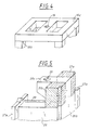
- FIG. 5 A third variant is shown in FIG. 5.
- This Variant is characterized in that at the top of the Base body (26) at least two tilt position detectors (21a, 21b) are arranged (e.g. proximity sensors).
- the force-generating Device (27a, 27b), the conical opening (29), the part (26c) of the base body (26) projecting into the middle and the connecting elements (28) are to the previous figures have already been described.
- the situation is already there the not shown here for reasons of clarity Tilting mirror on the mirror bearing explained in detail Service.
- the arrangement is essentially the same like the arrangement in Figures 1 and 2a, 2b, only that here position detectors on the base body (26) the current one Determine the position of the tilt mirror, not shown.
- a target movement is entered for the controlled tilting mirror into a control computer, which has a control voltage generated.
- This control voltage goes to the strip piezo actuators, whose movement is transferred to the tilting mirror.
- the tilt position detectors detect this tilting movement and generate a measuring voltage, which reaches the control computer. The latter then calculates the comparison of the target and actual values a correction voltage with which the control voltage is corrected.
- the pivot point is relatively close to the mirror surface, whereby the lateral emigration of the tilt mirror at Tilt can be kept very small (e.g. in the figure 3 tilting mirror shown is the lateral deflection at 5 ° tilt angle a maximum of 5% of a base side length).
- the location the mirror pivot point depends on the thickness of the Tilting mirror and the dimensioning of the webs under the Tilting mirror.
- Tilting mirror arrangement (31) has as drive elements or force-generating device no strip piezo actuators.
- the tilting mirror (32) again has a circular cone (33) its bottom. To the side of this circular cone (33) are two Bars (34a, 34b) arranged, which by a third bar (34c) are interconnected. To this extent, this corresponds Version of the version in the previous representations.
- the base body (36) has four lateral webs (36b), between each of which a coil (37a-37d) is attached. The coils (37a-37d) rest on it the height of the permanent magnets (38a-38d).
- the tilting mirror (32) moves in different directions.
- the webs (36b) arranged in the corners of the base body (36) carry the web projecting into the center of the base body (36) (36c) with the conical opening (39) for storing the Circular cone (33) of the tilting mirror (32).
- a control loop can be used also be built up in that the location of the reflected beam is detected. This can e.g. by happen a beam splitter, which is behind the tilt mirror assembly is attached and which is part of the radiation incident on an optical measuring arrangement (e.g. deflects an area detector array). There will be a deviation the actual value from the desired value determined, so causes the optical measuring arrangement a signal for control the tilting mirror assembly (31) until the tilting mirror (32) has taken the desired position.
- an optical measuring arrangement e.g. deflects an area detector array
- the invention is based on a point storage of the tilting mirror be limited to a base body. It is important that the storage is as smooth as possible and no jerky Movements occur when a movement is initiated.
- the force-generating device can consist of bending or strip piezo actuators or consist of coils and magnets.
- force generating device are all a force generating devices, which are built accordingly compact and where the power generation becomes one Movement leads (e.g. electric linear motors, gas, liquid or otherwise moving pistons, etc.).
- the restraint can be a spring or a other element that is capable of doing so ensure that the tilting mirror is not in an inclined position removed from the base body in an uncontrolled manner.
- the restrained Forces are generated by fields (e.g. magnetic).
- a weight compensation device around the pivot point makes sense, if the tilting mirror arrangement in a defined Is operated inclined. She then ensures that they are there occurring weight forces, which the tilting mirror from its Bring to rest, be caught and not by the force-generating Facility must be intercepted.
- This Weight compensation device can in the example in FIG. 6 can be realized in that one or two coils permanent get some bias depending on the relative position of the tilting mirror arrangement.
- tilt position detector usable, which carry out a distance measurement.
- sensors for position detection usable which is a field emanating from the tilting mirror (e.g. a magnetic field) if the field strength is dependent is from the tilt angle.
- any spatial array can be used side by side, which is required for the apparatus in which the tilting mirror arrangements ultimately used. there do not necessarily need the mirror surfaces directly next to each other lie, but can also be offset perpendicular to the mirror plane be arranged.
- the base body need not necessarily be rectangular. When shaping the base body and thus the tilting mirror however, care should be taken to ensure that the array of tilting mirror arrangements has a high packing density since this is one the particular advantages of the tilting mirror arrangement according to the invention is.
- the tilt mirror assemblies joined together must also not all the same size since the individual Tilting mirror arrangements can be controlled discretely.
- the necessary position change device can according to the known prior art be executed.
Landscapes
- Physics & Mathematics (AREA)
- General Physics & Mathematics (AREA)
- Optics & Photonics (AREA)
- Optical Elements Other Than Lenses (AREA)
- Rear-View Mirror Devices That Are Mounted On The Exterior Of The Vehicle (AREA)
- Optical Recording Or Reproduction (AREA)
- Mechanical Light Control Or Optical Switches (AREA)
Description
- begrenzter Kippwinkel um die x- bzw. y-Achse um normalerweise einem Winkel kleiner als 1°;
- eingeschränkte Baugröße (Dabei erfordern gewisse Kippwinkel eine gewisse Mindestbaugröße oder auch maximale Baugröße, was jeweils störend ist.);
- Baugröße der Kippspiegelanordnung deutlich größer als Spiegelfläche, insbesondere hinter der Spiegelfläche bei kleinen Kippspiegeln (d.h. mit den Spiegeln nach dem bekannten Stand der Technik sind keine hohen Packungsdichten erreichbar); oder
- komplizierte Herstellungstechnik der bekannten zweiachsigen Kippspiegel.
- Fig. 1
- eine dreidimensionale Ansichtsskizze einer zweiten Variante der erfindungsgemäßen Kippspiegelanordnung;
- Fig. 2a
- einen Schnitt durch die Spiegellagerung der in Figur 1 darstellten Kippspiegelanordnung in der Y-Z-Ebene;
- Fig. 2b
- einen Schnitt durch die Spiegellagerung der in Figur 1 dargestellten Kippspiegelanordnung in der X-Z-Ebene;
- Fig. 3
- eine seitliche Aufschnittsskizze einer ersten Variante der erfindungsgemäßen Kippspiegelanordnung;
- Fig. 4
- eine dreidimensionale Ansicht des spiegelseitigen Basiskörpers aus Fig. 3;
- Fig. 5
- eine Ansicht einer dritten Variante der erfindungsgemäßen Kippspiegelanordnung aus Fig. 3 mit Positionssensoren;
- Fig. 6
- eine vierte Variante der erfindungsgemäßen Kippspiegelanordnung mit einer anderen krafterzeugenden Einrichtung in seitlicher Ansicht und
- Fig. 6a
- einen Schnitt durch die Anordnung aus Figur 6.
- deren Baugröße in x-y-Richtung nicht größer ist als die Spiegelplatte (wobei diese kleiner als 10 mm sein kann) ;
- welche herstellungstechnisch einfach ist;
- welche somit (relativ) preiswert herstellbar ist; und
- welche einen Kippwinkel von +/- 5° und mehr aufweisen kann.
- Kaman Instrumentation Measuring Systems, 1500 Garden of the Gods Road, Colorado Springs, Colorado 80907 USA als Displacement measuring Systems KD-2300-.5SU, bzw. andere Sensoren aus den Baureihen KD-2300/2310/2350; oder von
- Micro-Epsilon Messtechnik GmbH & Co. KG, Königbacher Straße 15, D-8359 Ortenburg-Dorfbach, Deutschland unter der Bezeichnung U05.08 bzw. U05.10 bzw. U05.12.
- Hoechst CeramTec aus Deutschland und werden dort als monolithische Vielschichtaktuatoren oder auch als piezoelektrische Biegeelemente bezeichnet.
Claims (17)
- Kippspiegelanordnung, welche mindestens einen Kippspiegel (2) mit einer ebenen Spiegelfläche (2a), einen Basiskörper (6) und eine Spiegellagerung mit festem Drehpunkt zwischen dem Kippspiegel und dem Basiskörper besitzt, wobei der Kippspiegel eine Spiegeldiagonale kleiner 40 mm Länge aufweist und wobei die Anordnung Kippspiegel, Lagerung und Basiskörper derart unterhalb der Spiegeloberfläche angeordnet ist, daß sie in der Projektion der Spiegelebene nicht oder bei Auslenkung des Kippspiegels nur unwesentlich über diese hinausragt, dadurch gekennzeichnet, daß der Kippspiegel (2) über ein Punktlager (3, 9) auf dem Basiskörper (6) gelagert ist, wobei zum Erzeugen einer den Spiegel auf den Basiskörper zurückhaltenden Kraft zwischen dem Kippspiegel und dem Basiskörper eine Rückhaltevorrichtung (5c) die den festen Drehpunkt zwischen dem Kippspiegel und dem Basiskörper auch bei beliebiger Schräglage der Kippspiegelanordnung im Raum sicherstellt, angebracht ist.
- Kippspiegelanordnung nach Anspruch 1, dadurch gekennzeichnet, daß die Spiegellagerung bezüglich des Drehpunktes selbstzentrierend ist.
- Kippspiegelanordnung nach einem der Ansprüche 1-2, dadurch gekennzeichnet, daß der Kippspiegel und der Basiskörper eine viereckige Kontur aufweisen und die Spiegeldiagonale und die Basisdiagonale kleiner als 15 mm ist.
- Kippspiegelanordnung nach einem der Ansprüche 1-3, dadurch gekennzeichnet, daß der Kippwinkel größer als 0,5° ist.
- Kippspiegelanordnung nach Anspruch 1, dadurch gekennzeichnet, daß die Rückhaltevorrichtung (5c) als Feder ausgestaltet ist.
- Kippspiegelanordnung nach einem der Ansprüche 1-5, dadurch gekennzeichnet, daß für mindestens eine vorherbestimmte Vorzugsschräglage der Kippspiegelanordnung eine Gewichtsausgleichseinrichtung für den Kippspiegel angebracht bzw. angreifend ist.
- Kippspiegelanordnung nach einem der Ansprüche 1-6, dadurch gekennzeichnet, daß in der Kippspiegelanordnung eine krafterzeugende Einrichtung (7a, 7b) mit veränderlicher Kraftwirkung angeordnet ist, welche von außen angesteuert eine Veränderung des Kippwinkels bewirkt.
- Kippspiegelanordnung nach Anspruch 7, dadurch gekennzeichnet, daß an der Kippspiegelunterseite eine Verlängerung (4, 14) angebracht ist, auf welche die krafterzeugende Einrichtung mit veränderlicher Kraftwirkung wirkt.
- Kippspiegelanordnung nach einem der Ansprüche 7-8, dadurch gekennzeichnet, daß die krafterzeugende Einrichtung ein sich senkrecht zur Kippachse biegender Körper ist, welcher an seinem unteren Ende fest an dem Basiskörper befestigt ist, und daß zwischen Biegekörper und dem Kippspiegel eine mechanische Kopplung (8a, 8b) angebracht ist.
- Kippspiegelanordnung nach einem der Ansprüche 1-9, dadurch gekennzeichnet, daß die Spiegellagerung zumindest reibungsarm ist.
- Kippspiegelanordnung nach einem der Ansprüche 7-10, dadurch gekennzeichnet, daß die krafterzeugende Einrichtung (7a, 7b) ein Biege- oder Streifen-Piezoaktuator ist.
- Kippspiegelanordnung nach einem der Ansprüche 7-10, dadurch gekennzeichnet, daß die krafterzeugende Einrichtung mindestens eine Einrichtung (37a, 37c) mit veränderbarer magnetischer Feldstärke ist und daß an dem Kippspiegel zumindest ein starr befestigter Magnet (38a, 38b) in der Höhe einer ihn bewegen könnenden Spule angeordnet ist.
- Kippspiegelanordnung nach einem der Ansprüche 1-12, dadurch gekennzeichnet, daß unter der Unterseite des Kippspiegels mindestens ein Kipplagendetektor (21a, 21b) außerachsial zur Kippachse angeordnet ist.
- Array aus Kippspiegelanordnungen, dadurch gekennzeichnet, daß viele der Kippspiegelanordnungen nach einem der Ansprüche 1-13 in einem Array angeordnet sind.
- Array aus Kippspiegelanordnungen nach Anspruch 14, dadurch gekennzeichnet, daß das Array so gestaltet ist, daß ein weiteres, gleiches Array an allen Seiten angefügt werden kann.
- Array aus Kippspiegelanordnungen nach Anspruch 14, dadurch gekennzeichnet, daß das Array aus Kippspiegelanordnungen in einem Sechseckmuster angeordnet ist.
- Kippspiegelanordnung nach einem der Ansprüche 1-16, dadurch gekennzeichnet, daß an dem Basiskörper ein Steg angebracht ist, daß ein Halteteil (6c) des Stegs bis unter die Mitte der Unterseite des Kippspiegels ragend ist, daß auf der Oberseite des Halteteils eine kegelförmige Öffnung (9) mit einem Öffnungswinkel β angebracht ist, daß unter dem Kippspiegel ein nach unten weisender Kegel (3) mit einem Öffnungswinkel α angebracht ist, und daß der Betragswert des Winkels α kleiner als der Betragswert des Winkels β ist.
Applications Claiming Priority (2)
| Application Number | Priority Date | Filing Date | Title |
|---|---|---|---|
| DE19504568A DE19504568A1 (de) | 1995-02-11 | 1995-02-11 | Kippspiegelanordnung |
| DE19504568 | 1995-02-11 |
Publications (3)
| Publication Number | Publication Date |
|---|---|
| EP0726479A2 EP0726479A2 (de) | 1996-08-14 |
| EP0726479A3 EP0726479A3 (de) | 1997-07-02 |
| EP0726479B1 true EP0726479B1 (de) | 2002-05-08 |
Family
ID=7753714
Family Applications (1)
| Application Number | Title | Priority Date | Filing Date |
|---|---|---|---|
| EP96100889A Expired - Lifetime EP0726479B1 (de) | 1995-02-11 | 1996-01-23 | Kippspiegelanordnung |
Country Status (5)
| Country | Link |
|---|---|
| US (1) | US5668655A (de) |
| EP (1) | EP0726479B1 (de) |
| JP (1) | JPH0968661A (de) |
| KR (1) | KR960032036A (de) |
| DE (2) | DE19504568A1 (de) |
Cited By (2)
| Publication number | Priority date | Publication date | Assignee | Title |
|---|---|---|---|---|
| US7354168B2 (en) | 2002-02-09 | 2008-04-08 | Carl Zeiss Smt Ag | Facet mirror having a number of mirror facets |
| DE102013114822B3 (de) * | 2013-12-23 | 2014-11-20 | Ernst-Abbe-Fachhochschule Jena | Zweiachsige Kippvorrichtung |
Families Citing this family (19)
| Publication number | Priority date | Publication date | Assignee | Title |
|---|---|---|---|---|
| IT1286550B1 (it) * | 1996-02-13 | 1998-07-15 | El En S R L | Dispositivo e metodo di deflessione di un fascio laser mediante specchio singolo |
| GB2316762A (en) * | 1996-08-24 | 1998-03-04 | Marconi Gec Ltd | Oscillating the mirror of a scanner using piezoelectric elements |
| EP0831269B1 (de) * | 1996-09-19 | 2003-09-10 | Carl Zeiss | Kippvorrichtung |
| DE19739879A1 (de) * | 1996-09-19 | 1998-03-26 | Zeiss Carl Fa | Kippvorrichtung |
| KR200187391Y1 (ko) * | 1997-10-10 | 2000-07-01 | 윤종용 | 마그네트를이용한비디오카메라의손떨림보정장치 |
| US6230976B1 (en) * | 1998-10-19 | 2001-05-15 | Psc Scanning, Inc. | Pinless dithering assembly for data reading |
| US20030048551A1 (en) * | 2000-11-22 | 2003-03-13 | Strieber Louis Charles | Method of altering solar radiation influxing the earth |
| RU2205439C2 (ru) * | 2001-05-15 | 2003-05-27 | Михеев Геннадий Михайлович | Устройство для пространственного отклонения луча |
| US6738539B2 (en) * | 2001-10-03 | 2004-05-18 | Continuum Photonics | Beam-steering optical switching apparatus |
| DE10243229B4 (de) * | 2002-09-17 | 2005-03-03 | Bundesrepublik Deutschland, vertr. d. d. Bundesministerium für Wirtschaft und Arbeit, dieses vertr. d. d. Präsidenten der Physikalisch-Technischen Bundesanstalt | Optischer Kleinwinkelgenerator |
| US6947657B1 (en) * | 2004-05-28 | 2005-09-20 | Asian Pacific Microsystems, Inc. | Variable optical attenuator |
| US7643196B2 (en) * | 2005-12-16 | 2010-01-05 | The Charles Stark Draper Laboratory, Inc. | Systems, methods and devices for actuating a moveable miniature platform |
| US7709782B2 (en) * | 2006-01-17 | 2010-05-04 | Newport Corporation | Optical assembly with adjustable optical element and independently tunable position sensors |
| WO2012175116A1 (en) * | 2011-06-21 | 2012-12-27 | Carl Zeiss Smt Gmbh | Facet mirror device |
| DE102012200736A1 (de) * | 2012-01-19 | 2013-07-25 | Carl Zeiss Smt Gmbh | Spiegelanordnung, insbesondere zum Einsatz in einer mikrolithographischen Projektionsbelichtungsanlage |
| DE102012221831A1 (de) * | 2012-11-29 | 2014-06-05 | Carl Zeiss Smt Gmbh | Anordnung zur Aktuierung wenigstens eines optischen Elementes in einem optischen System |
| US11867558B2 (en) * | 2017-02-13 | 2024-01-09 | Mks Technology, Inc. | Self-homing optical device |
| DE102022107598A1 (de) * | 2022-03-30 | 2023-10-05 | Raylase Gmbh | 1Ausgewuchtete Spiegeleinheit für eine Laserablenkvorrichtung und entsprechendes Auswuchtverfahren |
| DE102022203433A1 (de) * | 2022-04-06 | 2023-10-12 | Carl Zeiss Smt Gmbh | Verbindung von komponenten einer optischen einrichtung |
Family Cites Families (13)
| Publication number | Priority date | Publication date | Assignee | Title |
|---|---|---|---|---|
| JPS53108403A (en) * | 1977-03-04 | 1978-09-21 | Sony Corp | Mirror supporting device for video disc |
| US4383763A (en) * | 1979-09-12 | 1983-05-17 | Litton Systems, Inc. | Controllable mirrors |
| SU949618A1 (ru) * | 1980-12-15 | 1982-08-07 | Каунасский Политехнический Институт Им.Антанаса Снечкуса | Сканирующее устройство |
| DE3213076A1 (de) * | 1982-04-07 | 1983-10-20 | Max Planck Gesellschaft zur Förderung der Wissenschaften e.V., 3400 Göttingen | Sekundaerspiegel-kippvorrichtung fuer ein spiegelteleskop |
| JPS6043230A (ja) * | 1983-08-18 | 1985-03-07 | Mitsubishi Electric Corp | 偏向ミラ−装置 |
| JPS60177316A (ja) * | 1984-02-24 | 1985-09-11 | Ngk Spark Plug Co Ltd | 光偏向装置 |
| US4708420A (en) * | 1984-05-24 | 1987-11-24 | The Commonwealth Of Australia | Focal plane scanning device |
| JPS6186722A (ja) * | 1984-10-05 | 1986-05-02 | Jgc Corp | 光偏向器 |
| DE3538898A1 (de) * | 1985-11-02 | 1987-05-07 | Zeiss Carl Fa | Elektro-magnetisch angetriebener schwingspiegel |
| US4691212A (en) * | 1985-11-14 | 1987-09-01 | Xerox Corporation | Piezoelectric optical beam deflector |
| US5170277A (en) * | 1988-05-11 | 1992-12-08 | Symbol Technologies, Inc. | Piezoelectric beam deflector |
| US5293265A (en) * | 1992-08-24 | 1994-03-08 | General Electric Company | Real time variable laser beam spinner |
| US5517347A (en) * | 1993-12-01 | 1996-05-14 | Texas Instruments Incorporated | Direct view deformable mirror device |
-
1995
- 1995-02-11 DE DE19504568A patent/DE19504568A1/de not_active Ceased
-
1996
- 1996-01-15 KR KR1019960000648A patent/KR960032036A/ko not_active Ceased
- 1996-01-23 EP EP96100889A patent/EP0726479B1/de not_active Expired - Lifetime
- 1996-01-23 DE DE59609172T patent/DE59609172D1/de not_active Expired - Fee Related
- 1996-02-08 US US08/598,703 patent/US5668655A/en not_active Expired - Fee Related
- 1996-02-13 JP JP8048467A patent/JPH0968661A/ja active Pending
Cited By (2)
| Publication number | Priority date | Publication date | Assignee | Title |
|---|---|---|---|---|
| US7354168B2 (en) | 2002-02-09 | 2008-04-08 | Carl Zeiss Smt Ag | Facet mirror having a number of mirror facets |
| DE102013114822B3 (de) * | 2013-12-23 | 2014-11-20 | Ernst-Abbe-Fachhochschule Jena | Zweiachsige Kippvorrichtung |
Also Published As
| Publication number | Publication date |
|---|---|
| KR960032036A (ko) | 1996-09-17 |
| JPH0968661A (ja) | 1997-03-11 |
| US5668655A (en) | 1997-09-16 |
| EP0726479A2 (de) | 1996-08-14 |
| EP0726479A3 (de) | 1997-07-02 |
| DE19504568A1 (de) | 1996-08-14 |
| DE59609172D1 (de) | 2002-06-13 |
Similar Documents
| Publication | Publication Date | Title |
|---|---|---|
| EP0726479A2 (de) | Kippspiegelanordnung | |
| JP2802317B2 (ja) | マイクロマニピュレータ | |
| DE3854128T2 (de) | Mikropositioniersysteme und -verfahren. | |
| DE3542154C2 (de) | ||
| DE69709440T2 (de) | Tragvorrichtung unter Verwendung magnetische Energie | |
| DE4023311C2 (de) | ||
| EP3063579B1 (de) | Justierbare lagerungsanordnung für ein relativ zu einer basis präzise zu positionierendes objekt | |
| SE509017C2 (sv) | Mikrodrivanordning | |
| EP2501023B1 (de) | Vertikaler Stellantrieb mit Schwerkraftkompensation | |
| WO2008022797A1 (de) | Projektionsbelichtungsanlage und optisches system | |
| DE102010025222A1 (de) | Steuerbare Spiegelanordnung, optisches System mit einer steuerbaren Spiegelanordnung und Verfahren zur Ansteuerung einer steuerbaren Spiegelanordnung | |
| EP0252745A2 (de) | Gerät zum Steuern relativer Verschiebungen | |
| WO2019020315A1 (de) | Gewichtskraftkompensationseinrichtung | |
| US7301257B2 (en) | Motion actuator | |
| DE69005689T2 (de) | Mechanische Objektplatte, insbesondere für ein Tunneleffektmikroskop. | |
| EP0831351B1 (de) | Kippvorrichtung | |
| EP1412692B1 (de) | Zielfernrohr | |
| WO2020177944A1 (de) | Aktuatoreinrichtung und verfahren zur ausrichtung eines optischen elements, optische baugruppe sowie projektionsbelichtungsanlage | |
| DE102013112357B4 (de) | Optische Einrichtung, Kamera sowie Verfahren zur Verschiebung einer optischen Achse | |
| EP0831269B1 (de) | Kippvorrichtung | |
| DE102013114822B3 (de) | Zweiachsige Kippvorrichtung | |
| EP4388563A1 (de) | Vorrichtung und verfahren zur steuerung und/oder regelung von bewegungen eines objekts | |
| DE102022209214A1 (de) | Einzelspiegel eines Pupillenfacettenspiegels und Pupillenfacettenspiegel für eine Beleuchtungsoptik einer Projektionsbelichtungsanlage | |
| EP0252174B1 (de) | Grobstellanordnung | |
| DE4426160A1 (de) | Lagerung für ein um mindestens eine Achse bewegliches Bauteil |
Legal Events
| Date | Code | Title | Description |
|---|---|---|---|
| PUAI | Public reference made under article 153(3) epc to a published international application that has entered the european phase |
Free format text: ORIGINAL CODE: 0009012 |
|
| AK | Designated contracting states |
Kind code of ref document: A2 Designated state(s): DE FR GB NL |
|
| PUAL | Search report despatched |
Free format text: ORIGINAL CODE: 0009013 |
|
| AK | Designated contracting states |
Kind code of ref document: A3 Designated state(s): DE FR GB NL |
|
| 17P | Request for examination filed |
Effective date: 19971205 |
|
| 17Q | First examination report despatched |
Effective date: 19980115 |
|
| GRAG | Despatch of communication of intention to grant |
Free format text: ORIGINAL CODE: EPIDOS AGRA |
|
| GRAG | Despatch of communication of intention to grant |
Free format text: ORIGINAL CODE: EPIDOS AGRA |
|
| GRAH | Despatch of communication of intention to grant a patent |
Free format text: ORIGINAL CODE: EPIDOS IGRA |
|
| GRAH | Despatch of communication of intention to grant a patent |
Free format text: ORIGINAL CODE: EPIDOS IGRA |
|
| REG | Reference to a national code |
Ref country code: GB Ref legal event code: IF02 |
|
| GRAA | (expected) grant |
Free format text: ORIGINAL CODE: 0009210 |
|
| AK | Designated contracting states |
Kind code of ref document: B1 Designated state(s): DE FR GB NL |
|
| REF | Corresponds to: |
Ref document number: 59609172 Country of ref document: DE Date of ref document: 20020613 |
|
| GBT | Gb: translation of ep patent filed (gb section 77(6)(a)/1977) |
Effective date: 20020720 |
|
| ET | Fr: translation filed | ||
| PGFP | Annual fee paid to national office [announced via postgrant information from national office to epo] |
Ref country code: NL Payment date: 20021227 Year of fee payment: 8 Ref country code: GB Payment date: 20021227 Year of fee payment: 8 |
|
| PGFP | Annual fee paid to national office [announced via postgrant information from national office to epo] |
Ref country code: FR Payment date: 20030110 Year of fee payment: 8 |
|
| PGFP | Annual fee paid to national office [announced via postgrant information from national office to epo] |
Ref country code: DE Payment date: 20030124 Year of fee payment: 8 |
|
| PLBE | No opposition filed within time limit |
Free format text: ORIGINAL CODE: 0009261 |
|
| STAA | Information on the status of an ep patent application or granted ep patent |
Free format text: STATUS: NO OPPOSITION FILED WITHIN TIME LIMIT |
|
| 26N | No opposition filed |
Effective date: 20030211 |
|
| PG25 | Lapsed in a contracting state [announced via postgrant information from national office to epo] |
Ref country code: GB Free format text: LAPSE BECAUSE OF NON-PAYMENT OF DUE FEES Effective date: 20040123 |
|
| PG25 | Lapsed in a contracting state [announced via postgrant information from national office to epo] |
Ref country code: NL Free format text: LAPSE BECAUSE OF NON-PAYMENT OF DUE FEES Effective date: 20040801 |
|
| PG25 | Lapsed in a contracting state [announced via postgrant information from national office to epo] |
Ref country code: DE Free format text: LAPSE BECAUSE OF NON-PAYMENT OF DUE FEES Effective date: 20040803 |
|
| GBPC | Gb: european patent ceased through non-payment of renewal fee |
Effective date: 20040123 |
|
| PG25 | Lapsed in a contracting state [announced via postgrant information from national office to epo] |
Ref country code: FR Free format text: LAPSE BECAUSE OF NON-PAYMENT OF DUE FEES Effective date: 20040930 |
|
| NLV4 | Nl: lapsed or anulled due to non-payment of the annual fee |
Effective date: 20040801 |
|
| REG | Reference to a national code |
Ref country code: FR Ref legal event code: ST |