EP0726452A2 - Angular displacement signalling device - Google Patents
Angular displacement signalling device Download PDFInfo
- Publication number
- EP0726452A2 EP0726452A2 EP96101290A EP96101290A EP0726452A2 EP 0726452 A2 EP0726452 A2 EP 0726452A2 EP 96101290 A EP96101290 A EP 96101290A EP 96101290 A EP96101290 A EP 96101290A EP 0726452 A2 EP0726452 A2 EP 0726452A2
- Authority
- EP
- European Patent Office
- Prior art keywords
- housing
- rotor
- angular displacement
- signal
- axis
- Prior art date
- Legal status (The legal status is an assumption and is not a legal conclusion. Google has not performed a legal analysis and makes no representation as to the accuracy of the status listed.)
- Withdrawn
Links
Images


Classifications
-
- G—PHYSICS
- G01—MEASURING; TESTING
- G01L—MEASURING FORCE, STRESS, TORQUE, WORK, MECHANICAL POWER, MECHANICAL EFFICIENCY, OR FLUID PRESSURE
- G01L3/00—Measuring torque, work, mechanical power, or mechanical efficiency, in general
- G01L3/02—Rotary-transmission dynamometers
- G01L3/04—Rotary-transmission dynamometers wherein the torque-transmitting element comprises a torsionally-flexible shaft
- G01L3/10—Rotary-transmission dynamometers wherein the torque-transmitting element comprises a torsionally-flexible shaft involving electric or magnetic means for indicating
- G01L3/107—Rotary-transmission dynamometers wherein the torque-transmitting element comprises a torsionally-flexible shaft involving electric or magnetic means for indicating involving potentiometric means
-
- G—PHYSICS
- G01—MEASURING; TESTING
- G01D—MEASURING NOT SPECIALLY ADAPTED FOR A SPECIFIC VARIABLE; ARRANGEMENTS FOR MEASURING TWO OR MORE VARIABLES NOT COVERED IN A SINGLE OTHER SUBCLASS; TARIFF METERING APPARATUS; MEASURING OR TESTING NOT OTHERWISE PROVIDED FOR
- G01D5/00—Mechanical means for transferring the output of a sensing member; Means for converting the output of a sensing member to another variable where the form or nature of the sensing member does not constrain the means for converting; Transducers not specially adapted for a specific variable
- G01D5/12—Mechanical means for transferring the output of a sensing member; Means for converting the output of a sensing member to another variable where the form or nature of the sensing member does not constrain the means for converting; Transducers not specially adapted for a specific variable using electric or magnetic means
- G01D5/14—Mechanical means for transferring the output of a sensing member; Means for converting the output of a sensing member to another variable where the form or nature of the sensing member does not constrain the means for converting; Transducers not specially adapted for a specific variable using electric or magnetic means influencing the magnitude of a current or voltage
- G01D5/16—Mechanical means for transferring the output of a sensing member; Means for converting the output of a sensing member to another variable where the form or nature of the sensing member does not constrain the means for converting; Transducers not specially adapted for a specific variable using electric or magnetic means influencing the magnitude of a current or voltage by varying resistance
- G01D5/165—Mechanical means for transferring the output of a sensing member; Means for converting the output of a sensing member to another variable where the form or nature of the sensing member does not constrain the means for converting; Transducers not specially adapted for a specific variable using electric or magnetic means influencing the magnitude of a current or voltage by varying resistance by relative movement of a point of contact or actuation and a resistive track
- G01D5/1655—Mechanical means for transferring the output of a sensing member; Means for converting the output of a sensing member to another variable where the form or nature of the sensing member does not constrain the means for converting; Transducers not specially adapted for a specific variable using electric or magnetic means influencing the magnitude of a current or voltage by varying resistance by relative movement of a point of contact or actuation and a resistive track more than one point of contact or actuation on one or more tracks
-
- G—PHYSICS
- G01—MEASURING; TESTING
- G01L—MEASURING FORCE, STRESS, TORQUE, WORK, MECHANICAL POWER, MECHANICAL EFFICIENCY, OR FLUID PRESSURE
- G01L5/00—Apparatus for, or methods of, measuring force, work, mechanical power, or torque, specially adapted for specific purposes
- G01L5/22—Apparatus for, or methods of, measuring force, work, mechanical power, or torque, specially adapted for specific purposes for measuring the force applied to control members, e.g. control members of vehicles, triggers
- G01L5/221—Apparatus for, or methods of, measuring force, work, mechanical power, or torque, specially adapted for specific purposes for measuring the force applied to control members, e.g. control members of vehicles, triggers to steering wheels, e.g. for power assisted steering
Definitions
- the present invention relates to signalling devices and more particularly relates to angular displacement signalling devices.
- Signalling devices have been constructed to indicate the degree of angular displacement between two members.
- devices have been proposed for signalling angular position through multiple revolutions of one member. Such devices sometimes relied on multiple potentiometers, or the like, connected for sequential operation as one member revolved. These were complex, relatively expensive devices. Furthermore such devices were frequently constructed so that calibration was required after the signalling device was connected to the relatively rotatable members. Still further, the prior art devices have not proposed devices for signalling both angular displacement and torque transmission of a rotating member. Devices of the sort referred to can be applied to vehicle steering columns.
- the present invention provides a new and improved angular displacement signalling device which comprises a housing, a torque transmitting unit extending through the housing and rotatable about an axis, a first rotor fixed to a first unit region for rotation relative to the housing, a second rotor fixed to a second unit region for rotation relative to the housing, an output member supported for movement with respect to the housing and the rotors, a transmission for transmitting drive between the output member and the first rotor so that the output member movement bears a predetermined relationship with movement of the first rotor, a first angular displacement signal generator comprising a first signal element fixed with respect to the output member and the second signal element fixed with respect to the housing, the signal elements coupled together and relatively moveable to produce a first angular displacement signal whose value changes in relation to the extent of the relative angular movement between the first rotor and the housing, and a second angular displacement signal generator comprising third and fourth signal elements coupled together to produce a second angular displacement signal having a value
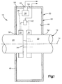
- FIG. 1 An angular displacement signalling device 10 constructed according to the present invention is illustrated schematically by Figure 1 of the drawings.
- the device 10 is constructed for association with a torque transmitting unit 12 which is rotatable about an axis 14.
- the device 10 is so constructed and arranged that it provides output signals indicative of both the angular displacement of the unit 12 as it rotates about the axis 14 and the torque transmitted by the unit 12 at any given time.
- the unit 12 may form part of a vehicle steering column which is capable of being revolved several times as the vehicle steering wheel is turned from "lock to lock.”
- the unit 12 is schematically illustrated as comprising first and second regions 20, 22 which are spaced axially apart along the unit.
- the illustrated unit 12 further includes a resiliently deformable torque transmitting element 24 connecting the regions 20, 22.
- the element 24 is resiliently twisted resulting in the first and second regions 20, 22 being angularly displaced about the axis 14 with respect to each other by an amount which depends upon the amount of torque transmitted.
- the element 24 has adequate strength to transmit any reasonably expectable torque between the first and second regions 20, 22.
- the element 24 can take any suitable form.
- the element 24 is schematically shown as integral with one of the regions 20, 22 and keyed to the other region.
- the element 24 is shown as a pin-like structure connected at its respective ends to regions 20, 22, respectively, formed on coaxial torsion transmitting shafts.
- the element 24 is illustrated as fixed to the respective shafts by splines.
- the signalling device 10 produces first and second electrical output signals having respective values indicating angular displacement of the shafts relative to the axis and torque transmission.
- the device 10 comprises a housing 30 disposed about, and fixed with respect to, the axis 14, first and second rotors 32, 34 each fixed to a respective one of the first and second regions 20, 22 for rotation about the axis 14, an output member 36 supported for movement with respect to the housing and the first and second rotors, a drive transmission 38 for transmitting drive between the output member 36 and the first rotor 32 and first and second angular displacement signal generators 40, 42.
- the signal generators 40, 42 produce respective angular displacement signals representing 1) the angular displacement of one of the first and second rotors relative to the housing (shaft angular displacement); and 2) the angular displacement between the first and second rotors (torque transmission).
- the preferred and illustrated housing 30 is constructed and arranged to enable the various components of the device 10 to be shipped and handled as a unit as well as assembled as a unitary structure to the unit 12.
- the housing 30 defines a chamber for receiving and surrounding the rotors 30, 32, the output member 36, the drive transmission 38, and the signal generators, 40, 42.
- the housing comprises a cup-like body 44 receiving the device components and a cover 46 which fits over the open end of the body 44 to close the chamber formed by the housing.
- the body 44 comprises a generally annular base wall 48 and a cylindrical sidewall 50 extending from the base wall 48 to a cover engaging lip 52.
- the cover 46 is pressed into engagement with the lip 52 and secured in place by ultrasonic welding, adhesive bonding material or other suitable means to complete assembly of the device 10.
- the cover 46 and base wall 48 are generally planar annular elements centered on the axis 14 and having aligned central openings 54 through which the torque transmitting unit 12 extends.
- the illustrated housing 30 is so constructed and arranged that in operation it is fixed with respect to the rotors and other moving elements of the device 10 located within it.
- the housing body 44 is constructed so that it can be securely supported within a surrounding shaft unit supporting casting, support frame, or the like, by the use of fasteners, keys, adhesives, etc. none of which is illustrated in the drawings.
- the rotor 32 is fixed to the shaft region 20 for rotation within the housing 30.
- the rotor 32 comprises an annular rotor body 60, a shaft locking structure 62 securing the rotor body to the shaft region 20, a signal generator support 64 projecting from the body 60, and a drive connection 66 coacting with the drive transmission 38.
- the rotor body 60 is a generally cylindrical member extending axially along the region 20 in the direction of the axis 14.
- the body 60 is illustrated as formed from a relatively rigid, high-strength molded plastic material.
- One axial end face 67 is surrounded by and projects through the adjacent housing cover opening 54.
- the opposite axial end 68 projects beyond the region 20 and is disposed adjacent the rotor 34.
- the shaft locking structure 62 accurately aligns and positively positions the body 60 on the shaft region 20.
- the locking structure 62 and the shaft region 20 are provided with conforming interlocking peripheral structures which ensure accurate angular alignment between the shaft region 20 and the rotor body 60.
- the interlocking peripheral structures are flat planar faces 70a, 70b formed, respectively, on the rotor body interior periphery and on the external periphery of the region 20. These peripheries thus each resemble the capital letter "D" in cross section.
- the illustrated body 60 carries circumferentially spaced key-like projections 72 along its inner periphery.
- the projections 72 are yieldable and at least somewhat resilient so that forcing the rotor body 60 onto the shaft region 20 resiliently crushes the projections 72 providing a strong frictional grip which anchors the body 60 against axial shifting relative to the shaft region 20.
- the signal generator support 64 in the embodiment of the invention illustrated by Figures 2 and 3 is a generally sector-shaped arm extending radially outwardly from the rotor body 60 and carrying a generally semi-cylindrical flange 74 at its radially outer periphery.
- the flange 74 carries an element of the signal generator 42.
- the flange 74 is concentric about the axis 14 and located remote from the body 60 so that a relatively small angular displacement of the body 60 about the axis 14 creates a relatively large flange and signal generator element movement.
- the drive connection 66 transfers motion from the rotor body 60 to the transmission 38 so that the output member 36 is positively driven upon motion of the rotor body 60 about the axis 14.
- the drive connection 66 is formed by a sun gear having its teeth molded into the exterior surface of the body 60.
- the illustrated transmission 38 is formed by a gear train between the output member 36 and the rotor 32. While a toothed gear arrangement is illustrated in the drawings, other forms of transmission and drive connection could be provided such as a chain drive, or a timing belt drive, or some other form of gearing. Any non-slipping drive transmission between the rotor 32 and the output member 36 can be employed, to the extent practical.
- the second rotor 34 is fixed to the shaft unit 22 for rotation with the unit 22 about the axis 14.
- the rotor 34 comprises an annular rotor body 80, a shaft locking structure 82 which fixedly secures rotor body 60 to the shaft region 22 and a signal generator support 84 projecting from the rotor body 80 radially away from the axis 14.
- the rotor body 80 is an annular, generally cylindrical member having one end 86 disposed closely adjacent the end 68 of the rotor body 60 and an opposite axially end 88 projecting through the adjacent central housing body opening 54.
- the axial rotor body end 88 is substantially flush with the plane of the housing base wall 48.
- the inner periphery of the opening 54 is spaced slightly radially away from the outer periphery of the rotor body end 88.
- the rotor body 80 is thus capable of rotation relative to the housing 30 as well as relative to the rotor body 60 since these elements, although closely spaced, normally do not contact each other.
- the rotor body end 68 forms a socket-like structure telescoped over the rotor body end 86.
- the shaft locking structure 82 precisely aligns the rotor body 80 radially with respect to the shaft region 22 as well as securing the rotor body 80 to the shaft region against radial or axial movements, as described in reference to the rotor body 60 and the shaft region 20.
- the construction and arrangement of the shaft locking structure 82 is identical to the structure 62. Reference should be made to the previous description for understanding the structure 82.
- the signal generator support 84 is formed by a sector-shaped arm projecting radially outwardly from the rotor body 80 and terminating in a cylindrical flange 92.
- the flange 92 is concentric about the axis 14 and extends parallel to and closely about the flange 74 on the rotor body 60.
- the flange 92 carries an element of the signal generator 42.
- the rotor bodies 80, 60 rotate relative to each other when torque transmitted by the unit 12 deflects the torsion element 24. Relative rotation between the rotor bodies creates relative angular movement between the flanges 74, 92.
- an output signal is produced which varies according to displacement of the signal generator elements they carry. Accordingly the signal generator 42 produces a signal having a value which depends upon the degree of torque transmitted by the unit 12.
- the illustrated and preferred output member 36 is driven from the rotor 32 for operating the signal generator 40 to produce an output signal whose value varies depending upon the rotational position of the rotor 32 relative to the housing 30.
- the output member 36 and signal generator 40 produce an output indicative of the angular position of the shaft region 20 about the axis 14.
- the preferred output member 36 is a generally flat annular molded plastic member having an inner periphery defining a ring gear 100 and an outer periphery carrying a signal generator support 104.
- the illustrated support 104 projects axially from the plane of the member 36 to a location adjacent the housing base wall 48.
- the axially projecting end of the support 104 carries a generally radially extending flange 106 which supports an element of the displacement signal generator 40 in position adjacent the housing base wall 48.
- the output member 36 and the transmission 38 are assembled to the housing cover to form a subassembly which is then assembled to the remaining components of the device.
- the drive transmission 38 is formed by a pinion gear assembly running in mesh with the sun gear 66 and the ring gear 100.
- the pinion gear assembly comprises a large diameter pinion gear 110 meshed with the sun gear and a smaller diameter pinion gear 112 fixed to the pinion gear 110 and meshed with the ring gear 100.
- the gears 110, 112 are supported for rotation about a common axis on a stub shaft 114 projecting from and integrally formed with the housing cover 46.
- the shaft 114 extends through the pinion gear central bores along their axis of rotation.
- the projecting stub shaft end is peened over after the pinion gears are mounted on it to secure the pinion gears in place to the housing cover.
- the pinion gear assembly thus aids in supporting the output member 36 relative to the housing cover.
- the output member 36 is supported on the housing cover by support fingers 116 (only one of which is illustrated) which latch the member 36 in place radially with respect to the axis 14 while enabling the member 36 to freely rotate about the axis 14.
- the latching fingers 116 are molded integrally with the housing cover 46 in a circumferentially extending array. Each finger 116 is resiliently flexible and provided with a cam and barb-like keeper structure 117 at its projecting end. See Fig. 2. The keeper structure captures the member 36 when the output member is pressed onto the housing cover.
- the pinion gear assembly is constructed and arranged such that a gear reduction of about 4:1 is realized between the rotor body 60 and the output member 36.
- the gear reduction provided is such that 4.2 revolutions of the shaft region 20 about the axis 14 results in the output member 36 revolving 350° about the axis 14.
- the angular displacement signal generator 40 is constructed and arranged to produce an electrical output signal having a value which varies depending upon the angular displacement of the shaft region 20 relative to the housing 30 through multiple shaft revolutions.
- the shaft region 20 makes about 4.2 revolutions about the axis 14 while producing output signals from the generator 40 varying throughout a predetermined range of signal values. A given output signal value thus corresponds to a predetermined shaft position.
- the signal generator 40 comprises a first signal generator element 130 carried by the output member 36 and a second element 132 carried by the housing 30.
- the elements 130, 132 are moved relative to each other resulting in the generation of the output signal.
- the elements 130, 132 are constructed and arranged so that relative motion between them changes electrical parameters which in turn alter the output signal value.
- the element 130 is preferably a U-shaped wiper formed from a thin strip of highly conductive spring material.
- the legs of the "U” project toward the housing base wall 48.
- the bight of the U-shaped element is securely fixed to the flange 106, for example by rivetting, ultrasonic welding, or the like, so that the wiper leg positions are accurately maintained relative to the output member 36.
- the element 132 is formed by parallel strips 140, 142 of electrical resistance material deposited on concentric circularly curved paths on a thick film body 144.
- the film body is formed by an annular non-conducting pliant plastic sheet which is adhered or otherwise fixedly secured in place to the housing base wall 48.
- the resistive strips 140, 142 are deposited on the film 144 at locations which are, and remain, aligned with the respective associated wiper leg.
- the illustrated film has the resistive strips deposited along the outer film peripheral portion so that the actual length of the deposited strip material from end to end is maximized. Adjacent ends of the resistive strips 140, 142 are attached to conductors printed on the film 144 and extending along the opposite side of the thick film 144 to terminals from which the signal is delivered from the housing via insulated leads.
- the signal element 130 is shifted from a limit position with respect to the resistive strips 140, 142 toward the opposite strip ends.
- the position signal value produced by the signal generator 40 increases as the length of resistive strip in the signal circuitry is reduced. Shaft region rotation in the opposite direction produces a decreasing position signal value.
- the resistive strip ends electrically contact respective insulated leads which are supported by the housing 30 and extend away from the housing to a suitable signal processor (not illustrated).
- the signal generator 42 is formed by a signal producing element 150 carried by the flange 74 on the rotor body 60 and a signal producing element 152 carried by the flange 92 on the rotor body 80.
- the signal producing element 150 is actually formed by two separate wipers 150a, 150b while the element 152 is formed by a thick film sheet 153 carrying strips, or pads, 154, 155, 156, 157 of resistive material deposited thereon. The film in turn is fixed to the flange 92 in registration with the wipers 150a, 150b.
- the wipers 150a, 150b are identical, each being formed by single elongated strip of copper alloy or other highly conductive spring metal. Each wiper defines a central section fixedly secured to the flange 74 and oppositely extending fingers defining tips urged into wiping electrical contact with a respective resistive strip on the film 153.
- the rotor bodies 60, 80 move relative to each other in response to changes in torque transmitted by the shaft unit 12.
- the wipers 150a, 150b shift circumferentially relative to the respective associated resistive strips 154, 155, 156, 157.
- Each wiper 150a, 150b bridges two resistive strips.
- the bridged resistive strips are connected across an output signal circuit so that as the associated wiper moves relative to the bridged resistive strips, the signal circuit resistance increases or decreases depending on the direction and extent of the relative movement.
- two electrically distinct, but complimentary, output signals are produced by the signal generator 42.
- the rotor bodies 60, 80 can be displaced relative to each other through a 4° shift when the torque transmitted by the shaft unit 12 varies from zero (0) to the torque level required to produce a maximum torque signal value in one direction or the other. Accordingly, the total range of relative motion between the rotor bodies 60, 80 is 8° and the output signals vary throughout their entire ranges as the shafts move relatively through the 8° range.
- the torque responsive output signals from the generator 43 are transmitted from the housing 30 via slip rings and brushes.
- the film 152 carries a projecting tab section 158 carrying deposited torque signal conductors and terminal pads associated with the respective resistive strips 154-157. Each terminal pad is electrically connected to a respective brush 160-163 fixed to the sector shaped support arm 84. Each brush is formed by a highly conductive copper alloy spring projecting from the support arm 84 to the film 144 on the housing base wall.
- the film 144 supports concentric annular conductive strips 164-167, each aligned with a respective brush 160-163 for conducting the torque signals along the housing base wall and to a suitable remote signal processor via insulated leads 168 ( Figure 4).
- the leads 168 are attached to respective terminal pads of the strips 164-167.
- the device 10 is assembled with the rotors 32, 34 nested together in the housing body 44 and the output member 36 and transmission 38 carried by the housing cover 46.
- the housing body 44 and contents are placed in a fixture and the cover 46 and associated parts are fitted onto the body 44, etc.
- the resistance across the angular displacement signal leads is measured to determine proper positioning of the rotors 32, 34.
- the rotors are accurately aligned in predetermined positions corresponding to a known shaft unit position which will exist when the shaft unit and the device 10 are assembled together at a later time.
- the cover 46 is then welded or bonded in place. After fabricating, the device 10 can be handled, transported and later installed on a shaft unit without any change in alignment of the device parts occurring.
- the rotor and the housing parts are each formed with a hole located for radial alignment about the axis 14 with corresponding holes in the other parts.
- the holes are aligned on a common axis 185 by rotating one of the rotors.
- the device parts remain essentially in their predetermined relative positions.
- a removable pin 190 is inserted through the holes and secured in place to the device 10.
- the device 10 is subsequently assembled to a shaft unit 12 as a unitary precalibrated component.
- the device 10 is initially assembled to the shaft region 22.
- the device 10 is oriented with respect to the shaft region so that the flat engaging surfaces on the shaft region 22 and the interior periphery of the rotor 34 are aligned.
- a pressing tool (not shown) engages the outwardly facing end 154 of the rotor body 60 and forces the device 10 onto the shaft region 22.
- the rotor body 60 engages and transmits the mounting force directly to the rotor body 80 so the housing components and other elements of the device 10 are not over-stressed.
- Installation is completed by attaching the torque transmitting element 24 and the second shaft region 22 to the first shaft region.
- the second shaft region is aligned with the rotor body 60 so that the conforming flat surfaces on the rotor body and the shaft region are aligned when the second shaft region is angularly related properly to the first shaft region.
- the second shaft region 22 is then pressed into the rotor body 60.
- the slightly resilient nature of the shaft locking structures 72, 82 not only frictionally secures the rotor bodies in place but also provides for a limited degree of "spring back" away from the direction of pressing motion so that a slight clearance between the rotor bodies 60, 80 exists after installation of the device 10.
- the pin 190 is next removed to free the internal device components 10 for relative movement. Because the device components are accurately aligned with each other before installation and since the shaft regions 22, 24 are properly aligned with the rotor bodies 60, 80 during installation, further calibration is not necessary. It should be noted that the pin 190 and aligned holes may be replaced by adhesive tape for temporarily securing the rotors together after calibration. The tape is applied to the inner peripheries of the rotors to prevent relative rotation before the device 10 is assembled to the shaft regions. The tape is removed just before placing the device on the shaft region. It is also possible that shear pins or other frangible connectors might be employed for the same purpose.
- the housing 30 can be fixed with respect to the unit 12 by any suitable structure.
- the housing can be formed with spine-like projections interfitting with conforming recesses in a shaft unit supporting bearing housing, or can be keyed in place to such a housing. Any suitable form of attachment for securing the housing 30 against motion relative to the axis 14 can be employed.
Abstract
Description
- The present invention relates to signalling devices and more particularly relates to angular displacement signalling devices.
- Signalling devices have been constructed to indicate the degree of angular displacement between two members. In some cases, devices have been proposed for signalling angular position through multiple revolutions of one member. Such devices sometimes relied on multiple potentiometers, or the like, connected for sequential operation as one member revolved. These were complex, relatively expensive devices. Furthermore such devices were frequently constructed so that calibration was required after the signalling device was connected to the relatively rotatable members. Still further, the prior art devices have not proposed devices for signalling both angular displacement and torque transmission of a rotating member. Devices of the sort referred to can be applied to vehicle steering columns.
- The present invention provides a new and improved angular displacement signalling device which comprises a housing, a torque transmitting unit extending through the housing and rotatable about an axis, a first rotor fixed to a first unit region for rotation relative to the housing, a second rotor fixed to a second unit region for rotation relative to the housing, an output member supported for movement with respect to the housing and the rotors, a transmission for transmitting drive between the output member and the first rotor so that the output member movement bears a predetermined relationship with movement of the first rotor, a first angular displacement signal generator comprising a first signal element fixed with respect to the output member and the second signal element fixed with respect to the housing, the signal elements coupled together and relatively moveable to produce a first angular displacement signal whose value changes in relation to the extent of the relative angular movement between the first rotor and the housing, and a second angular displacement signal generator comprising third and fourth signal elements coupled together to produce a second angular displacement signal having a value which varies in relation to the angular displacement between the first and second rotors.
- Other features and advantages of the invention will become apparent from the following detailed description of a preferred embodiment made with reference to the accompanying drawings.
-
- Figure 1 is a schematic illustration of an angular displacement signalling device embodying the present invention associated with a shaft unit;
- Figure 2 is a cross-sectional view of an angular displacement signalling device constructed according to the invention;
- Figure 3 is an enlarged fragmentary view of part of Figure 2; and,
- Figure 4 is an exploded perspective view of the angular displacement signalling device illustrated by Figure 2.
- An angular
displacement signalling device 10 constructed according to the present invention is illustrated schematically by Figure 1 of the drawings. Thedevice 10 is constructed for association with atorque transmitting unit 12 which is rotatable about anaxis 14. Thedevice 10 is so constructed and arranged that it provides output signals indicative of both the angular displacement of theunit 12 as it rotates about theaxis 14 and the torque transmitted by theunit 12 at any given time. Theunit 12 may form part of a vehicle steering column which is capable of being revolved several times as the vehicle steering wheel is turned from "lock to lock." - Referring to Figure 1, the
unit 12 is schematically illustrated as comprising first andsecond regions unit 12 further includes a resiliently deformabletorque transmitting element 24 connecting theregions unit 12 transmits torque, theelement 24 is resiliently twisted resulting in the first andsecond regions axis 14 with respect to each other by an amount which depends upon the amount of torque transmitted. - The
element 24 has adequate strength to transmit any reasonably expectable torque between the first andsecond regions element 24 can take any suitable form. In Figure 1, theelement 24 is schematically shown as integral with one of theregions element 24 is shown as a pin-like structure connected at its respective ends toregions element 24 is illustrated as fixed to the respective shafts by splines. - The
signalling device 10 produces first and second electrical output signals having respective values indicating angular displacement of the shafts relative to the axis and torque transmission. Thedevice 10 comprises ahousing 30 disposed about, and fixed with respect to, theaxis 14, first andsecond rotors second regions axis 14, anoutput member 36 supported for movement with respect to the housing and the first and second rotors, adrive transmission 38 for transmitting drive between theoutput member 36 and thefirst rotor 32 and first and second angulardisplacement signal generators signal generators - The preferred and illustrated
housing 30 is constructed and arranged to enable the various components of thedevice 10 to be shipped and handled as a unit as well as assembled as a unitary structure to theunit 12. Thehousing 30 defines a chamber for receiving and surrounding therotors output member 36, thedrive transmission 38, and the signal generators, 40, 42. The housing comprises a cup-like body 44 receiving the device components and acover 46 which fits over the open end of thebody 44 to close the chamber formed by the housing. Thebody 44 comprises a generallyannular base wall 48 and acylindrical sidewall 50 extending from thebase wall 48 to a coverengaging lip 52. - The
cover 46 is pressed into engagement with thelip 52 and secured in place by ultrasonic welding, adhesive bonding material or other suitable means to complete assembly of thedevice 10. Thecover 46 andbase wall 48 are generally planar annular elements centered on theaxis 14 and having alignedcentral openings 54 through which thetorque transmitting unit 12 extends. The illustratedhousing 30 is so constructed and arranged that in operation it is fixed with respect to the rotors and other moving elements of thedevice 10 located within it. For this purpose thehousing body 44 is constructed so that it can be securely supported within a surrounding shaft unit supporting casting, support frame, or the like, by the use of fasteners, keys, adhesives, etc. none of which is illustrated in the drawings. - The
rotor 32 is fixed to theshaft region 20 for rotation within thehousing 30. Therotor 32 comprises anannular rotor body 60, ashaft locking structure 62 securing the rotor body to theshaft region 20, asignal generator support 64 projecting from thebody 60, and adrive connection 66 coacting with thedrive transmission 38. - The
rotor body 60 is a generally cylindrical member extending axially along theregion 20 in the direction of theaxis 14. Thebody 60 is illustrated as formed from a relatively rigid, high-strength molded plastic material. Oneaxial end face 67 is surrounded by and projects through the adjacent housing cover opening 54. The oppositeaxial end 68 projects beyond theregion 20 and is disposed adjacent therotor 34. - The
shaft locking structure 62 accurately aligns and positively positions thebody 60 on theshaft region 20. Thelocking structure 62 and theshaft region 20 are provided with conforming interlocking peripheral structures which ensure accurate angular alignment between theshaft region 20 and therotor body 60. In the illustrated embodiment, the interlocking peripheral structures are flatplanar faces region 20. These peripheries thus each resemble the capital letter "D" in cross section. - The illustrated
body 60 carries circumferentially spaced key-like projections 72 along its inner periphery. Theprojections 72 are yieldable and at least somewhat resilient so that forcing therotor body 60 onto theshaft region 20 resiliently crushes theprojections 72 providing a strong frictional grip which anchors thebody 60 against axial shifting relative to theshaft region 20. - The signal generator support 64 in the embodiment of the invention illustrated by Figures 2 and 3 is a generally sector-shaped arm extending radially outwardly from the
rotor body 60 and carrying a generallysemi-cylindrical flange 74 at its radially outer periphery. Theflange 74 carries an element of thesignal generator 42. As therotor 32 rotates about theaxis 14 the signal generator element carried by theflange 74 rotates about theaxis 14. Theflange 74 is concentric about theaxis 14 and located remote from thebody 60 so that a relatively small angular displacement of thebody 60 about theaxis 14 creates a relatively large flange and signal generator element movement. - The
drive connection 66 transfers motion from therotor body 60 to thetransmission 38 so that theoutput member 36 is positively driven upon motion of therotor body 60 about theaxis 14. In the illustrated embodiment of the invention, thedrive connection 66 is formed by a sun gear having its teeth molded into the exterior surface of thebody 60. The illustratedtransmission 38 is formed by a gear train between theoutput member 36 and therotor 32. While a toothed gear arrangement is illustrated in the drawings, other forms of transmission and drive connection could be provided such as a chain drive, or a timing belt drive, or some other form of gearing. Any non-slipping drive transmission between therotor 32 and theoutput member 36 can be employed, to the extent practical. - The
second rotor 34 is fixed to theshaft unit 22 for rotation with theunit 22 about theaxis 14. Therotor 34 comprises anannular rotor body 80, ashaft locking structure 82 which fixedly securesrotor body 60 to theshaft region 22 and asignal generator support 84 projecting from therotor body 80 radially away from theaxis 14. - The
rotor body 80 is an annular, generally cylindrical member having oneend 86 disposed closely adjacent theend 68 of therotor body 60 and an oppositeaxially end 88 projecting through the adjacent centralhousing body opening 54. The axialrotor body end 88 is substantially flush with the plane of thehousing base wall 48. The inner periphery of theopening 54 is spaced slightly radially away from the outer periphery of therotor body end 88. Therotor body 80 is thus capable of rotation relative to thehousing 30 as well as relative to therotor body 60 since these elements, although closely spaced, normally do not contact each other. In the preferred device the rotor body end 68 forms a socket-like structure telescoped over therotor body end 86. - The
shaft locking structure 82 precisely aligns therotor body 80 radially with respect to theshaft region 22 as well as securing therotor body 80 to the shaft region against radial or axial movements, as described in reference to therotor body 60 and theshaft region 20. The construction and arrangement of theshaft locking structure 82 is identical to thestructure 62. Reference should be made to the previous description for understanding thestructure 82. - The
signal generator support 84 is formed by a sector-shaped arm projecting radially outwardly from therotor body 80 and terminating in acylindrical flange 92. Theflange 92 is concentric about theaxis 14 and extends parallel to and closely about theflange 74 on therotor body 60. Theflange 92 carries an element of thesignal generator 42. Therotor bodies unit 12 deflects thetorsion element 24. Relative rotation between the rotor bodies creates relative angular movement between theflanges signal generator 42 produces a signal having a value which depends upon the degree of torque transmitted by theunit 12. - The illustrated and
preferred output member 36 is driven from therotor 32 for operating thesignal generator 40 to produce an output signal whose value varies depending upon the rotational position of therotor 32 relative to thehousing 30. In other words, theoutput member 36 andsignal generator 40 produce an output indicative of the angular position of theshaft region 20 about theaxis 14. Thepreferred output member 36 is a generally flat annular molded plastic member having an inner periphery defining aring gear 100 and an outer periphery carrying asignal generator support 104. The illustratedsupport 104 projects axially from the plane of themember 36 to a location adjacent thehousing base wall 48. The axially projecting end of thesupport 104 carries a generally radially extendingflange 106 which supports an element of thedisplacement signal generator 40 in position adjacent thehousing base wall 48. - In the
preferred device 10 theoutput member 36 and thetransmission 38 are assembled to the housing cover to form a subassembly which is then assembled to the remaining components of the device. Thedrive transmission 38 is formed by a pinion gear assembly running in mesh with thesun gear 66 and thering gear 100. The pinion gear assembly comprises a largediameter pinion gear 110 meshed with the sun gear and a smallerdiameter pinion gear 112 fixed to thepinion gear 110 and meshed with thering gear 100. Thegears stub shaft 114 projecting from and integrally formed with thehousing cover 46. Theshaft 114 extends through the pinion gear central bores along their axis of rotation. The projecting stub shaft end is peened over after the pinion gears are mounted on it to secure the pinion gears in place to the housing cover. The pinion gear assembly thus aids in supporting theoutput member 36 relative to the housing cover. - In addition to being supported by the pinion gear assembly the
output member 36 is supported on the housing cover by support fingers 116 (only one of which is illustrated) which latch themember 36 in place radially with respect to theaxis 14 while enabling themember 36 to freely rotate about theaxis 14. The latchingfingers 116 are molded integrally with thehousing cover 46 in a circumferentially extending array. Eachfinger 116 is resiliently flexible and provided with a cam and barb-like keeper structure 117 at its projecting end. See Fig. 2. The keeper structure captures themember 36 when the output member is pressed onto the housing cover. - The pinion gear assembly is constructed and arranged such that a gear reduction of about 4:1 is realized between the
rotor body 60 and theoutput member 36. In the illustrated and preferred embodiment of the invention the gear reduction provided is such that 4.2 revolutions of theshaft region 20 about theaxis 14 results in theoutput member 36 revolving 350° about theaxis 14. - The angular
displacement signal generator 40 is constructed and arranged to produce an electrical output signal having a value which varies depending upon the angular displacement of theshaft region 20 relative to thehousing 30 through multiple shaft revolutions. Theshaft region 20 makes about 4.2 revolutions about theaxis 14 while producing output signals from thegenerator 40 varying throughout a predetermined range of signal values. A given output signal value thus corresponds to a predetermined shaft position. - The
signal generator 40 comprises a firstsignal generator element 130 carried by theoutput member 36 and asecond element 132 carried by thehousing 30. When theoutput member 36 is driven about theaxis 14 theelements elements - The
element 130 is preferably a U-shaped wiper formed from a thin strip of highly conductive spring material. The legs of the "U" project toward thehousing base wall 48. The bight of the U-shaped element is securely fixed to theflange 106, for example by rivetting, ultrasonic welding, or the like, so that the wiper leg positions are accurately maintained relative to theoutput member 36. - The
element 132 is formed byparallel strips thick film body 144. The film body is formed by an annular non-conducting pliant plastic sheet which is adhered or otherwise fixedly secured in place to thehousing base wall 48. Theresistive strips film 144 at locations which are, and remain, aligned with the respective associated wiper leg. The illustrated film has the resistive strips deposited along the outer film peripheral portion so that the actual length of the deposited strip material from end to end is maximized. Adjacent ends of theresistive strips film 144 and extending along the opposite side of thethick film 144 to terminals from which the signal is delivered from the housing via insulated leads. - As the
shaft region 20 rotates from one of its extreme positions with respect to thehousing 30, thesignal element 130 is shifted from a limit position with respect to theresistive strips signal generator 40 increases as the length of resistive strip in the signal circuitry is reduced. Shaft region rotation in the opposite direction produces a decreasing position signal value. In the preferred and illustrated embodiment of the invention the resistive strip ends electrically contact respective insulated leads which are supported by thehousing 30 and extend away from the housing to a suitable signal processor (not illustrated). - The
signal generator 42 is formed by asignal producing element 150 carried by theflange 74 on therotor body 60 and asignal producing element 152 carried by theflange 92 on therotor body 80. In the preferred and illustrated embodiment thesignal producing element 150 is actually formed by twoseparate wipers element 152 is formed by athick film sheet 153 carrying strips, or pads, 154, 155, 156, 157 of resistive material deposited thereon. The film in turn is fixed to theflange 92 in registration with thewipers - The
wipers flange 74 and oppositely extending fingers defining tips urged into wiping electrical contact with a respective resistive strip on thefilm 153. - The
rotor bodies shaft unit 12. Thewipers resistive strips wiper device 10 two electrically distinct, but complimentary, output signals are produced by thesignal generator 42. Therotor bodies shaft unit 12 varies from zero (0) to the torque level required to produce a maximum torque signal value in one direction or the other. Accordingly, the total range of relative motion between therotor bodies - In the illustrated
device 10, the torque responsive output signals from the generator 43 are transmitted from thehousing 30 via slip rings and brushes. As best seen in Figure 4, thefilm 152 carries a projectingtab section 158 carrying deposited torque signal conductors and terminal pads associated with the respective resistive strips 154-157. Each terminal pad is electrically connected to a respective brush 160-163 fixed to the sector shapedsupport arm 84. Each brush is formed by a highly conductive copper alloy spring projecting from thesupport arm 84 to thefilm 144 on the housing base wall. Thefilm 144 supports concentric annular conductive strips 164-167, each aligned with a respective brush 160-163 for conducting the torque signals along the housing base wall and to a suitable remote signal processor via insulated leads 168 (Figure 4). The leads 168 are attached to respective terminal pads of the strips 164-167. - An important feature of the invention resides in the construction of the new signalling device as a precalibrated module suited for quick, easy assembly to a shaft unit, or the like, so that device calibration is not required after assembly. In the preferred embodiment the
device 10 is assembled with therotors housing body 44 and theoutput member 36 andtransmission 38 carried by thehousing cover 46. Thehousing body 44 and contents are placed in a fixture and thecover 46 and associated parts are fitted onto thebody 44, etc. The resistance across the angular displacement signal leads is measured to determine proper positioning of therotors device 10 are assembled together at a later time. Thecover 46 is then welded or bonded in place. After fabricating, thedevice 10 can be handled, transported and later installed on a shaft unit without any change in alignment of the device parts occurring. - In the illustrated embodiment, the rotor and the housing parts are each formed with a hole located for radial alignment about the
axis 14 with corresponding holes in the other parts. When thedevice 10 has been assembled, the holes are aligned on acommon axis 185 by rotating one of the rotors. The device parts remain essentially in their predetermined relative positions. Aremovable pin 190 is inserted through the holes and secured in place to thedevice 10. - The
device 10 is subsequently assembled to ashaft unit 12 as a unitary precalibrated component. Preferably thedevice 10 is initially assembled to theshaft region 22. Thedevice 10 is oriented with respect to the shaft region so that the flat engaging surfaces on theshaft region 22 and the interior periphery of therotor 34 are aligned. A pressing tool (not shown) engages the outwardly facingend 154 of therotor body 60 and forces thedevice 10 onto theshaft region 22. Therotor body 60 engages and transmits the mounting force directly to therotor body 80 so the housing components and other elements of thedevice 10 are not over-stressed. - Installation is completed by attaching the
torque transmitting element 24 and thesecond shaft region 22 to the first shaft region. The second shaft region is aligned with therotor body 60 so that the conforming flat surfaces on the rotor body and the shaft region are aligned when the second shaft region is angularly related properly to the first shaft region. Thesecond shaft region 22 is then pressed into therotor body 60. The slightly resilient nature of theshaft locking structures rotor bodies device 10. - The
pin 190 is next removed to free theinternal device components 10 for relative movement. Because the device components are accurately aligned with each other before installation and since theshaft regions rotor bodies pin 190 and aligned holes may be replaced by adhesive tape for temporarily securing the rotors together after calibration. The tape is applied to the inner peripheries of the rotors to prevent relative rotation before thedevice 10 is assembled to the shaft regions. The tape is removed just before placing the device on the shaft region. It is also possible that shear pins or other frangible connectors might be employed for the same purpose. - The
housing 30 can be fixed with respect to theunit 12 by any suitable structure. For example, the housing can be formed with spine-like projections interfitting with conforming recesses in a shaft unit supporting bearing housing, or can be keyed in place to such a housing. Any suitable form of attachment for securing thehousing 30 against motion relative to theaxis 14 can be employed. - While a single preferred construction of a signalling device embodying the present invention has been illustrated and described in considerable detail the present invention is not to be considered limited to the precise construction disclosed. Various adaptations, modifications and uses of the invention may occur to those skilled in the art to which the invention relates. The intention is to cover hereby all such adaptations, modifications and uses which fall within the spirit or scope of the appended claims.
Claims (4)
- An angular displacement signalling device comprising:
a housing disposed about an axis;
a shaft unit extending through said housing rotatable with respect to said housing about said axis, said shaft unit comprising first and second shaft regions spaced axially apart along said shaft unit, said shaft unit resiliently deformed in response to torque transmitted by said shaft unit to angularly displace one of said shaft regions relative to the other by an amount related to the torque being transmitted;
a first rotor fixed to said first shaft region for rotation with said first shaft region relative to said housing and said second shaft region;
a second rotor fixed to said second shaft region for rotation with said second shaft region relative to said housing and said first shaft region;
an output member supported for movement with respect to said housing and said first and second rotors;
a transmission for transmitting drive between said output member and said first rotor, said transmission reacting so that said movement of said output member bears a predetermined relationship with movement of said first rotor;
a first angular displacement signal generator comprising a first signal element fixed with respect to said output member and a second signal element fixed with respect to said housing, said signal elements coupled together and relatively movable to produce a first angular displacement signal whose value changes in relation to the extent of relative angular movement between one of said first and second rotors and said housing; and,
a second angular displacement signal generator comprising third and fourth signal elements coupled together to produce a second angular displacement signal having a value which varies in relation to the angular displacement between said first and second rotors. - An angular displacement signalling device constructed for association with a torque transmitting unit rotatable about an axis, said unit comprising first and second unit regions spaced axially apart along said unit, said unit resiliently deformed in response to torque transmitted by said unit to angularly displace one of said regions relative to the other by an amount related to the torque being transmitted, the signalling device comprising:
a housing disposed about said axis;
a first rotor fixed to said first region for rotation with said first region relative to said housing and said second region;
a second rotor fixed to said second region for rotation with said second region relative to said housing and said first region;
an output member supported for movement with respect to said housing and said first and second rotors;
a transmission for transmitting drive between said output member and said first rotor, said transmission reacting so that said movement of said output member bears a predetermined relationship with movement of said first rotor;
a first angular displacement signal generator comprising a first signal element fixed with respect to said output member and a second signal element fixed with respect to said housing, said signal elements coupled together and relatively movable to produce a first angular displacement signal whose value changes in relation to the extent of relative angular movement between one of said first and second rotors and said housing; and,
a second angular displacement signal generator comprising third and fourth signal elements coupled together to produce a second angular displacement signal having a value which varies in relation to the angular displacement between said first and second rotors. - A device for producing electrical output signals indicative of angular displacement comprising:a. a housing defining a chamber surrounding a rotation axis, said axis extending through a housing opening;b. a member disposed in said chamber for rotation about said axis relative to said housing, said member having a support arm radially spaced from said axis;c. a signal generator comprising a first signal generating element carried by said support arm for rotation about said axis with said member and a second signal generating element supported within said chamber, said first and second signal generating elements relatively movable about said axis to produce an electrical output signal having a value which varies in relation to the extent of relative movement between said elements; and,d. structure temporarily securing said member to said housing in a predetermined position fixed against rotation about said axis, said securing structure comprising a portion effective to fix said first and second signal generating elements in predetermined positions relative to each other.
- A method of fabricating a device for signalling angular displacement comprising:a. providing a housing defining a chamber surrounding an axis with spaced housing openings disposed about said axis;b. supporting first and second rotor members and an output member in said housing for rotation about said axis, and connecting a drive transmission between one of said rotor members and said output member so that said output member rotates a fixed fraction of the amount said one rotor member rotates;c. aligning axial rotor member bores along said axis, with opposite rotor member end surfaces surrounded by respective housing openings and adjacent rotor member ends disposed for abutting contact;d. stationing first and second electrical signal generators in said housing, said first signal generator producing signal values varying in direct relation to the angular displacement between said output member and housing and said second signal generator producing signals varying in direct relationship to angular displacement between said first and second rotor members;e. engaging an end surface of one of said first and second rotor members and urging said rotor members into abutting relationship to move said other rotor member bore onto a shaft region for securing the rotor member and shaft region together;f. moving a second shaft region into the bore of said one rotor member for securing said second shaft region and said one rotor member.
Applications Claiming Priority (2)
| Application Number | Priority Date | Filing Date | Title |
|---|---|---|---|
| US384928 | 1982-06-04 | ||
| US08/384,928 US5661466A (en) | 1995-02-07 | 1995-02-07 | Angular displacement signalling device |
Publications (2)
| Publication Number | Publication Date |
|---|---|
| EP0726452A2 true EP0726452A2 (en) | 1996-08-14 |
| EP0726452A3 EP0726452A3 (en) | 1997-07-16 |
Family
ID=23519328
Family Applications (1)
| Application Number | Title | Priority Date | Filing Date |
|---|---|---|---|
| EP96101290A Withdrawn EP0726452A3 (en) | 1995-02-07 | 1996-01-30 | Angular displacement signalling device |
Country Status (3)
| Country | Link |
|---|---|
| US (1) | US5661466A (en) |
| EP (1) | EP0726452A3 (en) |
| CA (1) | CA2168819A1 (en) |
Cited By (5)
| Publication number | Priority date | Publication date | Assignee | Title |
|---|---|---|---|---|
| DE19745823A1 (en) * | 1997-10-16 | 1999-04-29 | Sensor Instr Gmbh | Torque and rotation angle measuring device e.g. for motor vehicle |
| EP0968903A1 (en) * | 1998-06-30 | 2000-01-05 | Alps Electric Co., Ltd. | Rotation detector for multi-rotation body |
| WO2000000377A1 (en) * | 1998-06-26 | 2000-01-06 | Zf Lenksysteme Gmbh | Electrically assisted power steering system for motor vehicles |
| EP1475621A2 (en) * | 2003-05-06 | 2004-11-10 | Delphi Technologies, Inc. | Torque Sensor |
| CN114034241A (en) * | 2022-01-11 | 2022-02-11 | 四川永星电子有限公司 | Precise coaxial quadruple angular displacement sensor |
Families Citing this family (6)
| Publication number | Priority date | Publication date | Assignee | Title |
|---|---|---|---|---|
| JP2000146720A (en) * | 1998-11-10 | 2000-05-26 | Kayaba Ind Co Ltd | Potentiometer of electric power steering device |
| JP4474341B2 (en) * | 2005-07-26 | 2010-06-02 | 日立オートモティブシステムズ株式会社 | Electric power steering device |
| FR3026568B1 (en) * | 2014-09-26 | 2023-01-06 | Thales Sa | INTEGRATED ANTENNA DEVICE |
| DK3098622T3 (en) * | 2015-05-29 | 2020-03-09 | Consilium Sal Navigation Ab | HULL-FITTED ELECTRONIC DEVICE FOR A VESSEL |
| DE102016104275A1 (en) * | 2016-03-09 | 2017-09-14 | Valeo Schalter Und Sensoren Gmbh | A method for producing a torque sensor device for a motor vehicle by ultrasonic welding, torque sensor device, steering system and motor vehicle |
| US10325582B2 (en) * | 2016-07-28 | 2019-06-18 | Navico Holding As | Transducer mounting assembly |
Citations (4)
| Publication number | Priority date | Publication date | Assignee | Title |
|---|---|---|---|---|
| DE2501521A1 (en) * | 1975-01-16 | 1976-07-22 | Porsche Ag | Measuring device for powered vehicle steering systems - gives torque and angular readings from steering column unit |
| US4922761A (en) * | 1988-02-25 | 1990-05-08 | Mitsubishi Denki Kabushiki Kaisha | Steering torque detector |
| US5133216A (en) * | 1990-11-14 | 1992-07-28 | Bridges Robert H | Manipulator integral force sensor |
| EP0555987B1 (en) * | 1992-02-12 | 1996-12-11 | Lucas Industries public limited company | Optical torque sensors and steering systems for vehicles incorporating them |
Family Cites Families (19)
| Publication number | Priority date | Publication date | Assignee | Title |
|---|---|---|---|---|
| US2873760A (en) * | 1958-01-06 | 1959-02-17 | New York Air Brake Co | Safety vavle |
| US3308846A (en) * | 1963-10-16 | 1967-03-14 | Westinghouse Canada Ltd | Relief valve improvement |
| US3580352A (en) * | 1969-01-21 | 1971-05-25 | Gen Motors Corp | Steering torque servo |
| US3983953A (en) * | 1971-07-28 | 1976-10-05 | Gemmer-France | Servo mechanism |
| DE2658721A1 (en) * | 1976-12-24 | 1978-07-06 | Braukmann Armaturen | SAFETY VALVE |
| US4596271A (en) * | 1980-10-02 | 1986-06-24 | Brundage Robert W | Fluid pressure device |
| US4485843A (en) * | 1981-05-05 | 1984-12-04 | Wolff Robert C | Variable pressure relief and control valve |
| US4631923A (en) * | 1983-10-21 | 1986-12-30 | Devron Engineering Limited | Solenoid operated check valve |
| US4656409A (en) * | 1984-06-22 | 1987-04-07 | Honda Giken Kogyo Kabushiki Kaisha | Electromagnetic servo unit |
| JPS6130462A (en) * | 1984-07-20 | 1986-02-12 | Honda Motor Co Ltd | Electromagnetic servo unit |
| US4676331A (en) * | 1984-12-20 | 1987-06-30 | Kabushiki Kaisha Toyoda Jidoshokki Seisakusho | Torque detecting apparatus for electrical power steering system |
| FR2586807B1 (en) * | 1985-09-03 | 1993-11-26 | Aisin Seiki Kk | TORQUE DETECTOR, PARTICULARLY FOR POWER STEERING OF VEHICLE |
| US4871039A (en) * | 1987-04-03 | 1989-10-03 | Koyo Seiko Co., Ltd. | Power steering system incorporating electric motor |
| US4838074A (en) * | 1987-04-06 | 1989-06-13 | Mitsubishi Denki Kabushiki Kaisha | Steering torque detecting device |
| US4799506A (en) * | 1987-05-20 | 1989-01-24 | Taylor Wesley L | Adjustable safety relief valve |
| US4932434A (en) * | 1988-01-25 | 1990-06-12 | Taylor Wesley L | Adjustable safety relief valve |
| JPH0620989Y2 (en) * | 1988-12-05 | 1994-06-01 | 日本精工株式会社 | Relative rotation detector |
| US5056556A (en) * | 1990-07-24 | 1991-10-15 | Kabushiki Kaisha Fujikoshi | Solenoid valve |
| US5230364A (en) * | 1991-04-06 | 1993-07-27 | Vickers, Incorporated | Pressure relief valve |
-
1995
- 1995-02-07 US US08/384,928 patent/US5661466A/en not_active Expired - Fee Related
-
1996
- 1996-01-30 EP EP96101290A patent/EP0726452A3/en not_active Withdrawn
- 1996-02-05 CA CA002168819A patent/CA2168819A1/en not_active Abandoned
Patent Citations (4)
| Publication number | Priority date | Publication date | Assignee | Title |
|---|---|---|---|---|
| DE2501521A1 (en) * | 1975-01-16 | 1976-07-22 | Porsche Ag | Measuring device for powered vehicle steering systems - gives torque and angular readings from steering column unit |
| US4922761A (en) * | 1988-02-25 | 1990-05-08 | Mitsubishi Denki Kabushiki Kaisha | Steering torque detector |
| US5133216A (en) * | 1990-11-14 | 1992-07-28 | Bridges Robert H | Manipulator integral force sensor |
| EP0555987B1 (en) * | 1992-02-12 | 1996-12-11 | Lucas Industries public limited company | Optical torque sensors and steering systems for vehicles incorporating them |
Cited By (9)
| Publication number | Priority date | Publication date | Assignee | Title |
|---|---|---|---|---|
| DE19745823A1 (en) * | 1997-10-16 | 1999-04-29 | Sensor Instr Gmbh | Torque and rotation angle measuring device e.g. for motor vehicle |
| WO2000000377A1 (en) * | 1998-06-26 | 2000-01-06 | Zf Lenksysteme Gmbh | Electrically assisted power steering system for motor vehicles |
| US6422336B1 (en) * | 1998-06-26 | 2002-07-23 | Zf Lenksysteme Gmbh | Electrically assisted power steering system for motor vehicles |
| EP0968903A1 (en) * | 1998-06-30 | 2000-01-05 | Alps Electric Co., Ltd. | Rotation detector for multi-rotation body |
| US6362469B1 (en) | 1998-06-30 | 2002-03-26 | Alps Electric Co., Ltd. | Rotation detector for multi-rotation body having detection window |
| EP1475621A2 (en) * | 2003-05-06 | 2004-11-10 | Delphi Technologies, Inc. | Torque Sensor |
| EP1475621A3 (en) * | 2003-05-06 | 2006-04-12 | Delphi Technologies, Inc. | Torque Sensor |
| CN114034241A (en) * | 2022-01-11 | 2022-02-11 | 四川永星电子有限公司 | Precise coaxial quadruple angular displacement sensor |
| CN114034241B (en) * | 2022-01-11 | 2022-03-22 | 四川永星电子有限公司 | Precise coaxial quadruple angular displacement sensor |
Also Published As
| Publication number | Publication date |
|---|---|
| EP0726452A3 (en) | 1997-07-16 |
| US5661466A (en) | 1997-08-26 |
| CA2168819A1 (en) | 1996-08-08 |
Similar Documents
| Publication | Publication Date | Title |
|---|---|---|
| US5661466A (en) | Angular displacement signalling device | |
| US4592241A (en) | Torque detector | |
| US4670679A (en) | Adjusting device with overload slip system | |
| US6341426B1 (en) | Rotation angle sensor and torque sensor | |
| US6658960B2 (en) | Transmission shift position sensor | |
| EP1661778B1 (en) | Motor apparatus | |
| RU2566595C2 (en) | Sensor of disc brake wear | |
| US5567874A (en) | Rotary position detecting device | |
| US20030131670A1 (en) | Torque measuring piezoelectric device and method | |
| US6291914B1 (en) | Rotational angle sensor | |
| EP2293419A1 (en) | Sensor magnet device, gear mechanism and speed reducing electric motor | |
| US4875367A (en) | Steering torque detecting device | |
| US20040079177A1 (en) | Apparatus for measuring rotational angles | |
| US6029543A (en) | Piezo-electric drive arrangement for a harmonic drive transmission | |
| US20020047347A1 (en) | Motor having rotational sensor | |
| US6427307B1 (en) | Low-hysteresis coupling method for angular-position and torque sensor | |
| US6532833B1 (en) | Torque measuring piezoelectric device and method | |
| JP4377067B2 (en) | Electric drive unit | |
| CN102706370B (en) | The accelerator open degree pick-up unit of vehicle | |
| EP0211687A1 (en) | A gear mechanism | |
| US20010022485A1 (en) | Ultrasonic motor | |
| EP0840028A1 (en) | Rotary position detector for motors | |
| US3982220A (en) | Variable resistance control | |
| US3378804A (en) | Resistive devices | |
| JP3525562B2 (en) | Rotational position detector |
Legal Events
| Date | Code | Title | Description |
|---|---|---|---|
| PUAI | Public reference made under article 153(3) epc to a published international application that has entered the european phase |
Free format text: ORIGINAL CODE: 0009012 |
|
| AK | Designated contracting states |
Kind code of ref document: A2 Designated state(s): DE FR GB IT |
|
| PUAL | Search report despatched |
Free format text: ORIGINAL CODE: 0009013 |
|
| AK | Designated contracting states |
Kind code of ref document: A3 Designated state(s): DE FR GB IT |
|
| 17P | Request for examination filed |
Effective date: 19971222 |
|
| 17Q | First examination report despatched |
Effective date: 20000407 |
|
| GRAG | Despatch of communication of intention to grant |
Free format text: ORIGINAL CODE: EPIDOS AGRA |
|
| GRAG | Despatch of communication of intention to grant |
Free format text: ORIGINAL CODE: EPIDOS AGRA |
|
| GRAH | Despatch of communication of intention to grant a patent |
Free format text: ORIGINAL CODE: EPIDOS IGRA |
|
| STAA | Information on the status of an ep patent application or granted ep patent |
Free format text: STATUS: THE APPLICATION IS DEEMED TO BE WITHDRAWN |
|
| 18D | Application deemed to be withdrawn |
Effective date: 20030303 |