EP0726222B1 - Method and device for separating a backing sheet from an adhesive sheet - Google Patents
Method and device for separating a backing sheet from an adhesive sheet Download PDFInfo
- Publication number
- EP0726222B1 EP0726222B1 EP95120160A EP95120160A EP0726222B1 EP 0726222 B1 EP0726222 B1 EP 0726222B1 EP 95120160 A EP95120160 A EP 95120160A EP 95120160 A EP95120160 A EP 95120160A EP 0726222 B1 EP0726222 B1 EP 0726222B1
- Authority
- EP
- European Patent Office
- Prior art keywords
- separation
- sheet
- adhesive
- free end
- adhesive sheet
- Prior art date
- Legal status (The legal status is an assumption and is not a legal conclusion. Google has not performed a legal analysis and makes no representation as to the accuracy of the status listed.)
- Expired - Lifetime
Links
Images






Classifications
-
- B—PERFORMING OPERATIONS; TRANSPORTING
- B65—CONVEYING; PACKING; STORING; HANDLING THIN OR FILAMENTARY MATERIAL
- B65H—HANDLING THIN OR FILAMENTARY MATERIAL, e.g. SHEETS, WEBS, CABLES
- B65H29/00—Delivering or advancing articles from machines; Advancing articles to or into piles
-
- B—PERFORMING OPERATIONS; TRANSPORTING
- B65—CONVEYING; PACKING; STORING; HANDLING THIN OR FILAMENTARY MATERIAL
- B65H—HANDLING THIN OR FILAMENTARY MATERIAL, e.g. SHEETS, WEBS, CABLES
- B65H41/00—Machines for separating superposed webs
-
- B—PERFORMING OPERATIONS; TRANSPORTING
- B65—CONVEYING; PACKING; STORING; HANDLING THIN OR FILAMENTARY MATERIAL
- B65C—LABELLING OR TAGGING MACHINES, APPARATUS, OR PROCESSES
- B65C9/00—Details of labelling machines or apparatus
- B65C9/0006—Removing backing sheets
-
- Y—GENERAL TAGGING OF NEW TECHNOLOGICAL DEVELOPMENTS; GENERAL TAGGING OF CROSS-SECTIONAL TECHNOLOGIES SPANNING OVER SEVERAL SECTIONS OF THE IPC; TECHNICAL SUBJECTS COVERED BY FORMER USPC CROSS-REFERENCE ART COLLECTIONS [XRACs] AND DIGESTS
- Y10—TECHNICAL SUBJECTS COVERED BY FORMER USPC
- Y10T—TECHNICAL SUBJECTS COVERED BY FORMER US CLASSIFICATION
- Y10T156/00—Adhesive bonding and miscellaneous chemical manufacture
- Y10T156/11—Methods of delaminating, per se; i.e., separating at bonding face
- Y10T156/1168—Gripping and pulling work apart during delaminating
- Y10T156/1195—Delaminating from release surface
-
- Y—GENERAL TAGGING OF NEW TECHNOLOGICAL DEVELOPMENTS; GENERAL TAGGING OF CROSS-SECTIONAL TECHNOLOGIES SPANNING OVER SEVERAL SECTIONS OF THE IPC; TECHNICAL SUBJECTS COVERED BY FORMER USPC CROSS-REFERENCE ART COLLECTIONS [XRACs] AND DIGESTS
- Y10—TECHNICAL SUBJECTS COVERED BY FORMER USPC
- Y10T—TECHNICAL SUBJECTS COVERED BY FORMER US CLASSIFICATION
- Y10T156/00—Adhesive bonding and miscellaneous chemical manufacture
- Y10T156/19—Delaminating means
- Y10T156/1978—Delaminating bending means
- Y10T156/1983—Poking delaminating means
-
- Y—GENERAL TAGGING OF NEW TECHNOLOGICAL DEVELOPMENTS; GENERAL TAGGING OF CROSS-SECTIONAL TECHNOLOGIES SPANNING OVER SEVERAL SECTIONS OF THE IPC; TECHNICAL SUBJECTS COVERED BY FORMER USPC CROSS-REFERENCE ART COLLECTIONS [XRACs] AND DIGESTS
- Y10—TECHNICAL SUBJECTS COVERED BY FORMER USPC
- Y10T—TECHNICAL SUBJECTS COVERED BY FORMER US CLASSIFICATION
- Y10T156/00—Adhesive bonding and miscellaneous chemical manufacture
- Y10T156/19—Delaminating means
- Y10T156/1994—Means for delaminating from release surface
-
- Y—GENERAL TAGGING OF NEW TECHNOLOGICAL DEVELOPMENTS; GENERAL TAGGING OF CROSS-SECTIONAL TECHNOLOGIES SPANNING OVER SEVERAL SECTIONS OF THE IPC; TECHNICAL SUBJECTS COVERED BY FORMER USPC CROSS-REFERENCE ART COLLECTIONS [XRACs] AND DIGESTS
- Y10—TECHNICAL SUBJECTS COVERED BY FORMER USPC
- Y10T—TECHNICAL SUBJECTS COVERED BY FORMER US CLASSIFICATION
- Y10T29/00—Metal working
- Y10T29/49—Method of mechanical manufacture
- Y10T29/49815—Disassembling
Definitions
- This invention relates to a separation method and device for separating a backing sheet from an adhesive sheet which comprises a base sheet whereon an adhesive is applied to one surface and the backing sheet is affixed to the base sheet.
- the rigidities of the base tape and backing paper and their difference and the adhesion of the adhesive to the backing paper must be considered in setting the contact surface area and the punch depth of the punch and die, and therefore separation is unreliable and not satisfactory. Also, since the base tape is permanently deformed together with the backing tape, the tape tends to bend, and this results in unevenness in the tape affixed to an object and makes it easier for the tape to come off the object to which it is adhered.
- US-A-4,173,510 discloses a method and a device for separating a backing sheet from an adhesive sheet, in which a corner at an end of the adhesive sheet is bent around a sharp bend to cause shearing and lengthwise offset between the backing sheet and the base sheet, and then the corner is released so that a difference in the forces that tend to straighten the backing sheet and the base sheet, respectively, drives apart the shear-weakened adhesive bond.
- EP-A-0 506 257 discloses another method and apparatus for separating a backing sheet from an adhesive sheet.
- This manually performed method employs a tool in the form of a lettering pen provided with a slot.
- the adhesive sheet is inserted into the slot and then bent by the operator rotating the lettering pen. Subsequently the adhesive sheet is removed from the slot of the lettering pen which causes the backing sheet and the base sheet to be separated from one another due to a difference in elasticity between the two members.
- US-A-3,028,280 discloses a method for separating a backing sheet from an adhesive sheet by using the fingers to apply a shearing load between the two.
- a friction coating is provided on the outer side of the backing sheet to facilitate applying the shearing load by means of a person's fingers.
- EP-A-0 383 157 discloses a hand-driven device for separating a backing sheet from an adhesive sheet. A corner of the adhesive sheet is clamped between two gripping surfaces of two respective members of which one is slidingly supported relative to the other. When the corner of the adhesive sheet is clamped, the exposed part of the adhesive sheet is bent at approximately a 90° angle and then one of the members is moved relative to the other. This causes the adhesive sheet to bunch up and to present a surface that may be easily grasped in order to peel the base sheet from the backing sheet.
- US-A-4,867,836 discloses a film peeling apparatus for peeling a film from a substrate that comprises film raising means for raising a part of the film from the substrate, and fluid jetting means for jetting fluid into between the film thus raised and the substrate.
- the film raising means includes a brush or an adhesive member.
- the film raising member comprises a rotor and a brush made up of a plurality of hard needles of resin or steel formed around the rotor. The hard needles of the brush are not uniform in length, and an end of the printed circuit board is made to abut against this brush so that the latter raises a part of the protective film on the printed circuit board.
- this prior art apparatus is usable only where the backing sheet is a stiff member like a printed circuit board.
- the invention is intended to provide a separation method for adhesive sheet, which can be automated and raises the reliability and efficiency of the operation that separates the backing sheet from adhesive tape. Another purpose is to provide a separation device for performing such method, which has a simple structure.
- the free end of the adhesive is bent in the front-to-back direction until slippage occurs between the adhesive and the backing sheet, whereby the extensibility or compressibility of the backing sheet overcomes the adhesive force of the adhesive, and while the adhesive force of the adhesive on the backing sheet weakens, whichever member of the adhesive sheet and backing sheet has the smaller radius of curvature protrudes slightly.
- the separation means from the adhesive sheet while in this state such that it traces the end surface of the free end, the base sheet and backing sheet rebound after time, resulting in the backing sheet separating from the adhesive on the base sheet. This forms a handhold at the edge of the adhesive sheet that is used to pull the backing sheet away from the adhesive sheet.
- the separation operation is repeated a plurality of times. Even if the backing sheet is not separated from the adhesive sheet by one separation operation, the adhesive strength of the adhesive is gradually weakened by repetition of the operation, and therefore even if there is deviation in the quality of the base sheet or the backing sheet of the adhesive sheet, or even if there is deviation in the adhesive strength of the adhesive, the backing sheet can be reliably separated from the adhesive sheet.
- the bending operation is preferably performed such that whichever member has the higher rigidity of the base sheet and backing sheet is on the outside of the bend and whichever member has the lower rigidity is on the inside of the bend, and the tracing operation is performed in the direction from the member with higher rigidity toward the member with lower rigidity.
- bending is performed within the elastic limit of whichever member of the base sheet and adhesive sheet has the larger elastic limit, and therefore this member returns to its original shape, but since bending is performed beyond the elastic limit of the member with the smaller elastic limit, this member undergoes plastic deformation and does not return to its original shape. That is, by bending the adhesive sheet, the two members, which are adhered to each other by adhesive, undergo elastic deformation and permanent deformation, respectively, and a force results that works against the adhesive force of the adhesive and tries to separate them when the adhesive sheet returns to its original shape, thus separating the backing sheet from the adhesive of the base sheet. This forms a handhold at the edge of the adhesive sheet that is used to pull the backing sheet away from the adhesive sheet.
- the period of repetition of the separation operation be longer than one-half the period of the characteristic vibration frequency of the free end of the adhesive sheet.
- the free end of the adhesive sheet be the corner of the adhesive sheet.
- the rigidity or elastic limit of the adhesive sheet can be actualized in a state in which the free end is extended to a certain degree, and by separating the part where the adhesive strength of the adhesive is excessively weakened as you go toward the edge of the free end, the backing sheet becomes easier to remove from the adhesive sheet.
- FIG. 1 is a perspective view of the tape printing device to which the separation method and separation device for adhesive tape of this invention is applied
- FIG. 2 is an enlargement showing the cut end of the adhesive tape (adhesive sheet) with a backing sheet after being printed in the tape printer
- FIGS. 3 and 4 are a perspective view and plan view, respectively, of the separation device.
- FIGS. 5, 6 and 7 are side views of the separation device for explaining the separation operation.
- tape printer 1 has keyboard 2 with many keys 2a on the front part and access lid 3 toward the back. Also, tape printer 1 contains a tape cartridge, printing mechanism, etc. (none of which are shown). On the side of tape printer 1 is disposed tape eject opening 4 from which adhesive tape 10 is ejected after printing, and on the front is disposed tape insertion opening 5 which is in communication with the separation device built into to tape printer 1.
- the user opens access lid 3 and loads a tape cartridge on which is wound fresh adhesive tape 10 of the desired width, after which he enters the necessary characters by operating keys 2a on keyboard 2, which are then printed by thermal transfer, etc., on above adhesive tape 10 being fed at a fixed speed.
- the feeding of adhesive tape 10 is stopped.
- the printed part of adhesive tape 10 is ejected from tape eject opening 4, and the user operates a cutter, not shown, by a manual or automatic operation to cut the ejected part of adhesive tape 10.
- This cut adhesive tape 10 is adhesive tape 10 with backing paper, and below is a detailed explanation of the separation method and separation device for this adhesive tape 10, but to make it easier to understand, the explanation will begin with the structure of adhesive tape 10 with backing paper.
- adhesive tape 10 comprises base tape (base sheet) 11, which is adhesive 11b applied to base material 11a, and backing paper (backing sheet) 12 to which base tape 11 is affixed by adhesive 11b.
- Base material 11a is made from commonly known polyvinyl chloride resin, polypropylene resin, etc.
- backing paper 12 is made from regular paper, etc. The above printing is performed on the surface of base material 11 a, and base tape 11 is applied to a selected object after removing backing paper 12 from adhesive tape 10. Therefore, backing paper 12 is there to prevent dirt, etc., from adhering to adhesive 11b until adhesive tape (base tape 11) 10 is to be used and can be removed from base tape 11 relatively easily. That is, backing paper 12 is treated with silicon, etc., and the adhesive force of adhesive 11b is very much smaller than its adhesive force on base material 11a.
- separation device 6 comprises motor (actuator mechanism) 7, separation member 8 attached to output shaft 7a of motor 7, and a pair of upper and lower support members (support means; see FIG. 4) 9 which support adhesive tape 10 leaving free end (corner) 10a.
- motor 7 has a single-unit structure with a reduction gear to make it possible to rotate separation member 8 at low speed.
- Separation member 8 is roughly a star-shaped rotating body with protrusions 8a in five locations around its circumference, and its outer member is made from silicon rubber, etc.
- Separation member 8 may be a roller shape as shown by the imaginary outline, or it may be gear shaped.
- the protrusion may be cam shaped at only one location, or plates may be disposed such that they radiate out from output shaft 7a.
- the upper and lower support members 9 also serve as an insertion path for adhesive tape 10 linked to above tape insertion opening 5 and is disposed such that inserted adhesive tape 10 is sandwiched. In this case, it is desirable that the gap between the pair of support members 9 becomes narrower from tape insertion opening 5 toward the back until it becomes nearly the thickness of adhesive tape 10 at the end. Inserted adhesive tape 10 is located by abutting against a stopper not shown in the figure, but the locating position is described in detail later.
- adhesive tape 10 When adhesive tape 10 is completely inserted in tape insertion opening 5 in the above configuration, adhesive tape 10 comes close to separation member 8 as shown in FIG. 3 and is finally positioned as indicated by the solid lines in FIG. 5. That is, one corner of the end of adhesive tape 10 moves inside the circle of rotation of separation member 8 so that it can come in contact with separation member 8.
- adhesive tape 10 be supported by the pair of support members 9 such that the corner of adhesive tape 10 with total thickness T becomes a triangular cantilever free end 10a whose dimensions on two sides are B and C.
- support members 9 may support adhesive tape 10 with a weak spring force capable of withstanding the force applied to it during the separation operation, and they may support adhesive tape 10 with a small gap between them and adhesive tape 10.
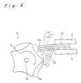
- separation member 8 After contact with one protrusion 8a formed on the outer circumference of separation member 8 ends, separation member 8 continues to rotate in the same direction. Before the next protrusion 8a gets into contact with the adhesive tape 10, the tape instantaneously recovers to its original state with impact because of its own elastic force. Also, adhesive tape 10 which has returned to its original state is positioned facing, in a non-contact state, one of the depressions respectively defined on separation member 8 between the protrusions 8a (see FIG. 6).
- This recovery of adhesive tape 10 to its original state occurs because the deformation due to bending is roughly within the elastic deformation of at least one of base tape 11 and backing paper 12 which make up adhesive tape 10.
- said base material 11a is made from resin and backing paper 12 is made from regular paper, and therefore base tape 11 has greater rigidity and a larger elastic limit than backing paper 12, and since the allowable bending stress is large, the recovery force of base tape 11 contributes the most to the recovery operation.
- the completed recovery state of adhesive tape 10 is shown in FIG. 6, but as shown in the same figure, adhesive tape 10 which has completed recovery returns to a state slightly bent from its initial state.
- base tape 11 in a case in which the rigidity of base tape 11 is greater than the rigidity of backing paper 12, base tape 11 instantaneously returns to its original position when contact with separation member 8 is released, but backing paper 12 remains in a roughly permanently bent state and does not recover or recovers little, thus resulting in a fixed bend condition.
- backing paper 12 Due to the instantaneous recovery by base tape 11 and the adhesive force of adhesive 11b, backing paper 12 will recover some, but as described above, recovery by backing paper 12 is not spontaneous and the bent condition of backing paper 12 resists the recovery force from base tape 11. This causes adhesive tape 10 to not completely recover and recovery to a slightly bent state. That is, adhesive 11b acts between base tape 11 and backing paper 12 to cause a reactive pulling state, and this results in strengthening the tendency of backing paper 12 to separate from base tape 11.
- separation device 6 can be made so as to be adapted to particular needs, thus facilitating its general use and avoiding the necessity of separate devices for respective needs.
- the time from when the user inserts adhesive tape 10 in said tape insertion opening 5 to perform separation until separation is complete is only 1 to several seconds even if the separation operation is performed several times.
- the user removes adhesive tape 10 from insertion opening 5, holds backing paper 12 at the separated corner in his fingers, and completely removes backing paper 12 from adhesive tape 10 by pulling in the lengthwise direction of base tape 11.
- this embodiment uses a simpler action and structure than the device of the half-cut system described in the prior art example and does not require a high level of precision, it is more cost effective, and since the shape after completion of separation, shown in FIG. 7, is hardly permanently deformed because bending is performed in the elastic deformation range of base tape 11, this deformation is hardly noticeable even when a printed base tape 11 is applied to an object.
- the difference in the rigidity of base tape 11 and separation paper 12 is utilized for one action. Therefore, a method and structure that can greatly utilize the difference in rigidity is desirable, and for this reason, it is desirable to use the corner of adhesive tape 10 as described above.
- the corner is used, and assuming the part indicated by the imaginary line Q is supported, the maximum stress when bent occurs at the position indicated by the imaginary line.
- the bending moment at this time is the product of the bending force multiplied by the length L of the perpendicular line from the tip of the corner to the imaginary line Q.
- the width of free end 10a does affect the stress generated in bending, but when the corner is used as free end 10a and is bent, the stress generated is not as great as when the width is uniform because the width of free end 10a gradually decreases from the imaginary line part toward the tip of the corner.
- the bending stress of the corner can be kept within the elastic limit with no permanent deformation at nearly an equal stress, and therefore as contact with separation member 8 is released, base tape 11 can instantaneously recover to the initial position.
- This support mode is the same for backing paper 12, but as described above, since backing paper 12 is made from regular paper, its rigidity is small, and therefore its recovery action is small, thus facilitating efficient separation as described above.
- the rigidity of base tape 11 need not necessarily be larger, and the rigidity of backing paper 12 can be made larger than the rigidity of base tape 11 and still obtain the same effect, Even in this case, separation member 8 is moved such that it travels from the member with the higher rigidity toward the other member, and therefore a structure should be used that bends the member with the higher rigidity toward the member with the lower rigidity.
- this period of repetition be longer than one-half the period of the characteristic vibration frequency of free end 10a of adhesive sheet 10, and in order to achieve this, the rotation speed of separation member 8 is set.
- backing paper 12 can be prevented from recovering by being pulled by base tape 11, thus contributing greatly to the separation action. If this is not done and the bending operation is started again before base tape 11 can completely recover, each of the above effects is lost and the timing of recovery of backing paper 12 tends to become the same as recovery of base tape 11. For this reason, it is best not to rotate separation member 8 too fast, and it is desirable to employ a reduction gear on motor 7.
- the corner used as free end 10a need not be an isosceles triangle, and therefore dimensions B and C noted above need not be the same. Further, a corner need not necessarily be used, and even if the edge of adhesive tape 10 is nearly parallel to the imaginary line that indicates the position of support member 9, a similar effect as this embodiment can be expected under the various conditions noted in this specification.
- the separation operation may be performed using the side of adhesive tape 10 as free end 10a. In this method, the separation length (lengths indicated by B and C in FIG. 3) that can be separated can be made longer while the separation interval can be made larger.
- separation member 8 of this embodiment need not be operated by motor 7, but rather the same effect as this embodiment can be obtained by using a handle or other configuration that can be operated by hand.
- FIG. 8 shows a structure wherein adhesive tape 10 with backing paper is held by support members 9 as in the first embodiment and moving member (separation member) 22 capable of moving linearly obliquely to the tape is moved horizontally to the right as indicated by the arrow while also being moved down and to the right as indicated by the other arrow. Though not shown, this moving member 22 is moved as required by a motor and linking mechanism.
- moving member 22 deforms mainly backing paper 12, and due to the elasticity of base tape (with adhesive 11b) 11, it is accompanied by an action that tries to remain at the position of the solid lines, while only backing sheet 12 reaches the area of permanent deformation as in the first embodiment.
- Separation may be completed by one of these operations, but if it is not completed, base tape 11 is deformed together with backing paper 12 and slippage occurs between the two in the longitudinal direction whereby the separation operation is furthered, and also since base tape 11 is deformed in the elastic deformation range, a recovery force acts on base tape 11.
- This jagged surface does not have to be extreme; i.e., about one-half the thickness of adhesive tape 10 will have sufficient effect. Also, by repeating this operation multiple times, both members 11, 12 can be completely separated.
- moving member 22 is moved horizontally and diagonally, but the embodiment is not limited to this in that moving member 22 may be moved vertically to bend adhesive tape 10 or any structure is possible as long as it traces the edge and then moves away from it.
- moving member 22 with multiple large protrusions 8a, a system results in which bending and release (separation operation) are repeated multiple times during movement in one direction (e.g., down and to the right as described above), thus further improving operation.
- moving member 22 be made from metal, plastic or a high friction rubber material with a large frictional force.
- moving member 22 may be automatically moved with a motor, etc., or moved manually.
- the third embodiment is explained by referring to FIG. 9.
- the third embodiment shows a manual separation method.
- 10 indicates adhesive tape with paper backing
- 24 is the moving member. It is desirable that moving member 24 be made from a material that demonstrates a high friction on adhesive tape 10, and as described above, it is desirable that a fine jagged surface be formed on it.
- adhesive tape 10 is bent by moving member 24 from the index finger side toward the thumb side (down direction).
- FIG. 10 The fourth embodiment is explained by referring to FIG. 10.
- 30 is a plate-shaped member having a radius at the end and jagged surface 33
- 31 is a plate-shaped member like 30 but does not necessarily have a jagged surface.
- These two plate-shaped members 30, 31 are linked so that they can rotate relative to each other on hinge 32, and opposing blades are formed or affixed at the radius of each of plate-shaped members 30, 31.
- the corner of adhesive tape 10 can be cut to form a radius.
- a spring not shown in the figure is disposed between plate-shaped members 30, 31 and keeps their blades continually separated.
- the user first holds adhesive tape 10 with backing paper in one hand and holds these plate-shaped members 30, 31 in the other hand. He then sandwiches the corner of adhesive 10 between these plate-shaped members 30, 31 and cuts the corner as if cutting a fingernail.
- Forming the corner of adhesive tape 10 into a radius or beveling the corners straight by the same method may be considered to be just normal trimming, but by doing this, adhesive tape 10 can be given a more label-like appearance.
- the trimming tool can also serve as moving member (separation member) 24 of the third embodiment.
- the separation operation of bending and releasing is performed on each component member of adhesive tape 10.
- this embodiment uses a structure in which the separation member is built into the trimming tool for adhesive tape 10, there is no need to pick up separate tools for trimming and separation, and since the trimming and separation operations can be performed one after the other, it is convenient and it is low cost.
- this method and structure which separate by supporting a corner whose end is a cantilever of the above-mentioned length in a free state and bending and releasing this part by the above-mentioned means, is a system that causes elastic deformation in at least one of the component members of adhesive tape 10 and permanent deformation in the other, when the corner is supported as described above, maximum stress is generated during bending in the part indicated by the imaginary line Q, but since the stress generated in each part with respect to the size of the bending moment can be made small due to the relationship between the length L of the vertical line from the tip of the corner in contact with separation member 8 to the imaginary line in the first embodiment and the beam width of free end 10a, it is possible to set one of the above materials within the range of elastic deformation, the contact surface area and adhesive strength between adhesive 11b and backing paper 12 are both small at the corner, and a handhold for separating is formed at the corner by the resistance to cutting when adhesive tape 10 is cut, and therefore separation at the corner can be performed most efficiently when processed by the methods and
Landscapes
- Engineering & Computer Science (AREA)
- Mechanical Engineering (AREA)
- Folding Of Thin Sheet-Like Materials, Special Discharging Devices, And Others (AREA)
- Adhesives Or Adhesive Processes (AREA)
- Adhesive Tape Dispensing Devices (AREA)
- Adhesive Tapes (AREA)
Description
- This invention relates to a separation method and device for separating a backing sheet from an adhesive sheet which comprises a base sheet whereon an adhesive is applied to one surface and the backing sheet is affixed to the base sheet.
- Recently, due to the simplification of the application of tape and other sheet-shaped members to objects on which they are affixed, these types of adhesive sheets are being used in various applications. In these cases, characters are imprinted on the surface of the base tape (base sheet) of the adhesive tape (adhesive sheet) formed for use as a label, and the base tape on which adhesive is applied is affixed to an object after removing the backing paper (backing sheet) from the adhesive tape. Removing the backing paper from the adhesive tape using your finger is extremely difficult, and various separation methods and devices have been proposed in the prior art.
- In the prior art, a type of separation method and device was disclosed in JP-A-57-98837. In this system, as shown in FIG. 13, base tape 52 (and adhesive 53) of
adhesive tape 50 is cut with a cutter leavingbacking paper 51 intact; a so-called half-cut is performed. The user would bendend member 50a, as indicated by the imaginary lines in FIG. 13, with his finger, and then usingend member 50a as a handhold he would separatebacking paper 51 from adhesive tape 50 (base tape 52). - In the prior art separation method and device disclosed in JP-A-5-169749, the corner of the adhesive tape is sandwiched between a punch and die and the adhesive tape is permanently deformed. In this case, due to the difference in rigidity between the base tape and the backing paper, they do not return to the same shape after being removed from the punch thus separating the backing paper from the adhesive tape, and this part is used as a handhold to remove the backing paper from the adhesive sheet.
- In the former separation method above, it is necessary to consistently perform the half-cut such that it cuts base tape 52 (and adhesive 53) to a depth of several microns to several tens of microns and leaves backing
paper 51 intact, thus requiring a high level of precision in the structure and control of the device. It was also necessary to leave about a 5-mm length atend 50a ofadhesive tape 50 as a handhold for separation, thus wastingadhesive tape 50. - In the latter separation method, the rigidities of the base tape and backing paper and their difference and the adhesion of the adhesive to the backing paper must be considered in setting the contact surface area and the punch depth of the punch and die, and therefore separation is unreliable and not satisfactory. Also, since the base tape is permanently deformed together with the backing tape, the tape tends to bend, and this results in unevenness in the tape affixed to an object and makes it easier for the tape to come off the object to which it is adhered.
- US-A-4,173,510 discloses a method and a device for separating a backing sheet from an adhesive sheet, in which a corner at an end of the adhesive sheet is bent around a sharp bend to cause shearing and lengthwise offset between the backing sheet and the base sheet, and then the corner is released so that a difference in the forces that tend to straighten the backing sheet and the base sheet, respectively, drives apart the shear-weakened adhesive bond.
- EP-A-0 506 257 discloses another method and apparatus for separating a backing sheet from an adhesive sheet. This manually performed method employs a tool in the form of a lettering pen provided with a slot. The adhesive sheet is inserted into the slot and then bent by the operator rotating the lettering pen. Subsequently the adhesive sheet is removed from the slot of the lettering pen which causes the backing sheet and the base sheet to be separated from one another due to a difference in elasticity between the two members.
- US-A-3,028,280 discloses a method for separating a backing sheet from an adhesive sheet by using the fingers to apply a shearing load between the two. A friction coating is provided on the outer side of the backing sheet to facilitate applying the shearing load by means of a person's fingers.
- EP-A-0 383 157 discloses a hand-driven device for separating a backing sheet from an adhesive sheet. A corner of the adhesive sheet is clamped between two gripping surfaces of two respective members of which one is slidingly supported relative to the other. When the corner of the adhesive sheet is clamped, the exposed part of the adhesive sheet is bent at approximately a 90° angle and then one of the members is moved relative to the other. This causes the adhesive sheet to bunch up and to present a surface that may be easily grasped in order to peel the base sheet from the backing sheet.
- US-A-4,867,836 discloses a film peeling apparatus for peeling a film from a substrate that comprises film raising means for raising a part of the film from the substrate, and fluid jetting means for jetting fluid into between the film thus raised and the substrate. For peeling a protective film from a printed circuit board the film raising means includes a brush or an adhesive member. In one embodiment, the film raising member comprises a rotor and a brush made up of a plurality of hard needles of resin or steel formed around the rotor. The hard needles of the brush are not uniform in length, and an end of the printed circuit board is made to abut against this brush so that the latter raises a part of the protective film on the printed circuit board. Apparently, this prior art apparatus is usable only where the backing sheet is a stiff member like a printed circuit board.
- The invention is intended to provide a separation method for adhesive sheet, which can be automated and raises the reliability and efficiency of the operation that separates the backing sheet from adhesive tape. Another purpose is to provide a separation device for performing such method, which has a simple structure.
- These purposes are achieved with a method and a device as claimed, respectively. Preferred embodiments of the invention are subject-matter of the dependent claims.
- In one embodiment of the method and device according to the invention, the free end of the adhesive is bent in the front-to-back direction until slippage occurs between the adhesive and the backing sheet, whereby the extensibility or compressibility of the backing sheet overcomes the adhesive force of the adhesive, and while the adhesive force of the adhesive on the backing sheet weakens, whichever member of the adhesive sheet and backing sheet has the smaller radius of curvature protrudes slightly. Further, by withdrawing the separation means from the adhesive sheet while in this state such that it traces the end surface of the free end, the base sheet and backing sheet rebound after time, resulting in the backing sheet separating from the adhesive on the base sheet. This forms a handhold at the edge of the adhesive sheet that is used to pull the backing sheet away from the adhesive sheet.
- The separation operation is repeated a plurality of times. Even if the backing sheet is not separated from the adhesive sheet by one separation operation, the adhesive strength of the adhesive is gradually weakened by repetition of the operation, and therefore even if there is deviation in the quality of the base sheet or the backing sheet of the adhesive sheet, or even if there is deviation in the adhesive strength of the adhesive, the backing sheet can be reliably separated from the adhesive sheet.
- When the base sheet and the backing sheet have different rigidities, the bending operation is preferably performed such that whichever member has the higher rigidity of the base sheet and backing sheet is on the outside of the bend and whichever member has the lower rigidity is on the inside of the bend, and the tracing operation is performed in the direction from the member with higher rigidity toward the member with lower rigidity. By means of this configuration, slippage occurs easily between the layers due to the difference in rigidity between the base sheet and the backing sheet, and since the member with the higher rigidity readily returns to its original shape while the member with the lower rigidity does not readily return to its original shape when the base sheet and the backing sheet rebound, re-adhesion between the base sheet and the backing sheet is prevented.
- In another embodiment of the method and device according to the invention for an adhesive sheet with differing elastic limits of the base sheet and the backing sheet bending is performed within the elastic limit of whichever member of the base sheet and adhesive sheet has the larger elastic limit, and therefore this member returns to its original shape, but since bending is performed beyond the elastic limit of the member with the smaller elastic limit, this member undergoes plastic deformation and does not return to its original shape. That is, by bending the adhesive sheet, the two members, which are adhered to each other by adhesive, undergo elastic deformation and permanent deformation, respectively, and a force results that works against the adhesive force of the adhesive and tries to separate them when the adhesive sheet returns to its original shape, thus separating the backing sheet from the adhesive of the base sheet. This forms a handhold at the edge of the adhesive sheet that is used to pull the backing sheet away from the adhesive sheet.
- When the bending operation is performed such that whichever member has the higher elastic limit of said base sheet and said backing sheet is on the outside of the bend and whichever member has the lower elastic limit is on the inside of the bend, whichever member of the base sheet and the backing sheet bent by the separation means is positioned on the outside of the bend undergoes elastic deformation and whichever member is positioned on the inside of the bend undergoes plastic deformation. Therefore, when the bending force is released, the member positioned on the outside returns to its original shape and the member positioned on the inside does not return to its original shape, thus causing both members to relax to an open position centered on the support member. That is, both members stabilize to a completely separate state.
- Furthermore, it is desirable that the period of repetition of the separation operation be longer than one-half the period of the characteristic vibration frequency of the free end of the adhesive sheet. By means of this configuration, sufficient time can be obtained for the adhesive sheet to recover completely after one separation operation, and therefore each separation operation can act fully on the adhesive sheet to more reliably separate the backing sheet from the adhesive sheet.
- It is desirable that the free end of the adhesive sheet be the corner of the adhesive sheet. By means of this configuration, the rigidity or elastic limit of the adhesive sheet can be actualized in a state in which the free end is extended to a certain degree, and by separating the part where the adhesive strength of the adhesive is excessively weakened as you go toward the edge of the free end, the backing sheet becomes easier to remove from the adhesive sheet.
- Further features and advantages of the present invention will be more easily understood from the following detailed description of preferred embodiments with reference to the drawings, in which:
- FIG. 1
- is a perspective view of a tape printer in which a separation device of an embodiment of the invention is built-in,
- FIG. 2
- is an enlarged side view showing the laminated structure of the adhesive tape,
- FIG. 3
- is a perspective view of the separation device of the first embodiment,
- FIG. 4
- is a plan view of the separation device of the first embodiment,
- FIG. 5
- is a side view showing the separation operation (1) of the separation device of the first embodiment,
- FIG. 6
- is a side view showing the separation operation (2) of the separation device of the first embodiment,
- FIG. 7
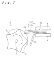
- is a side view showing the separation operation (3) of the separation device of the first embodiment,
- FIG. 8
- is a side view of the separation device of the second embodiment,
- FIG. 9
- is a perspective view of the separation device (member) of the third embodiment,
- FIG. 10
- is a perspective view of the separation device (member) of the fourth embodiment,
- FIG. 11
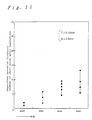
- is a graph showing the experimental results (1) of the fifth embodiment,
- FIG. 12
- is a graph showing the experimental results (2) of the fifth embodiment, and
- FIG. 13
- is a perspective view showing a separation method for adhesive tape of the prior art.
- The first embodiment of the invention is explained in detail by referring to FIGS. 1 to 7. FIG. 1 is a perspective view of the tape printing device to which the separation method and separation device for adhesive tape of this invention is applied, FIG. 2 is an enlargement showing the cut end of the adhesive tape (adhesive sheet) with a backing sheet after being printed in the tape printer, and FIGS. 3 and 4 are a perspective view and plan view, respectively, of the separation device. Also, FIGS. 5, 6 and 7 are side views of the separation device for explaining the separation operation.
- As shown in FIG. 1,
tape printer 1 haskeyboard 2 withmany keys 2a on the front part and access lid 3 toward the back. Also,tape printer 1 contains a tape cartridge, printing mechanism, etc. (none of which are shown). On the side oftape printer 1 is disposed tape eject opening 4 from whichadhesive tape 10 is ejected after printing, and on the front is disposedtape insertion opening 5 which is in communication with the separation device built into totape printer 1. - The user opens access lid 3 and loads a tape cartridge on which is wound fresh
adhesive tape 10 of the desired width, after which he enters the necessary characters by operatingkeys 2a onkeyboard 2, which are then printed by thermal transfer, etc., on aboveadhesive tape 10 being fed at a fixed speed. When printing is completed, the feeding ofadhesive tape 10 is stopped. At this time, the printed part ofadhesive tape 10 is ejected from tape eject opening 4, and the user operates a cutter, not shown, by a manual or automatic operation to cut the ejected part ofadhesive tape 10. - This cut
adhesive tape 10 isadhesive tape 10 with backing paper, and below is a detailed explanation of the separation method and separation device for thisadhesive tape 10, but to make it easier to understand, the explanation will begin with the structure ofadhesive tape 10 with backing paper. - As shown in FIG. 2,
adhesive tape 10 comprises base tape (base sheet) 11, which is adhesive 11b applied tobase material 11a, and backing paper (backing sheet) 12 to whichbase tape 11 is affixed by adhesive 11b.Base material 11a is made from commonly known polyvinyl chloride resin, polypropylene resin, etc., and backingpaper 12 is made from regular paper, etc. The above printing is performed on the surface ofbase material 11 a, andbase tape 11 is applied to a selected object after removingbacking paper 12 fromadhesive tape 10. Therefore, backingpaper 12 is there to prevent dirt, etc., from adhering to adhesive 11b until adhesive tape (base tape 11) 10 is to be used and can be removed frombase tape 11 relatively easily. That is, backingpaper 12 is treated with silicon, etc., and the adhesive force of adhesive 11b is very much smaller than its adhesive force onbase material 11a. - When
adhesive tape 10 configured like this is inserted in abovetape insertion opening 5 with thebase material 11a on which characters are printed up, a sensor or switch not shown in the drawing detects insertion ofadhesive tape 10 and the separation device is driven. This separates backingpaper 12 fromadhesive tape 10 at one corner at the front end ofadhesive tape 10. After removingadhesive tape 10 fromtape insertion opening 5, the user completely removes backingpaper 12 from adhesive tape (base tape 11) 10 using the part wherebacking paper 12 is separated from the corner as a hand hold and applies it to a selected object. - As shown in FIG. 3,
separation device 6 comprises motor (actuator mechanism) 7,separation member 8 attached tooutput shaft 7a ofmotor 7, and a pair of upper and lower support members (support means; see FIG. 4) 9 which supportadhesive tape 10 leaving free end (corner) 10a. In this case, it is desirable thatmotor 7 has a single-unit structure with a reduction gear to make it possible to rotateseparation member 8 at low speed.Separation member 8 is roughly a star-shaped rotating body withprotrusions 8a in five locations around its circumference, and its outer member is made from silicon rubber, etc.Separation member 8 may be a roller shape as shown by the imaginary outline, or it may be gear shaped. The protrusion may be cam shaped at only one location, or plates may be disposed such that they radiate out fromoutput shaft 7a. - The upper and
lower support members 9 also serve as an insertion path foradhesive tape 10 linked to abovetape insertion opening 5 and is disposed such that insertedadhesive tape 10 is sandwiched. In this case, it is desirable that the gap between the pair ofsupport members 9 becomes narrower fromtape insertion opening 5 toward the back until it becomes nearly the thickness ofadhesive tape 10 at the end. Insertedadhesive tape 10 is located by abutting against a stopper not shown in the figure, but the locating position is described in detail later. - When
adhesive tape 10 is completely inserted intape insertion opening 5 in the above configuration,adhesive tape 10 comes close toseparation member 8 as shown in FIG. 3 and is finally positioned as indicated by the solid lines in FIG. 5. That is, one corner of the end ofadhesive tape 10 moves inside the circle of rotation ofseparation member 8 so that it can come in contact withseparation member 8. - At this point, it is most desirable that
adhesive tape 10 be supported by the pair ofsupport members 9 such that the corner ofadhesive tape 10 with total thickness T becomes a triangular cantileverfree end 10a whose dimensions on two sides are B and C. However, since the force applied toadhesive tape 10 in the separation operation described below is not that large,support members 9 may supportadhesive tape 10 with a weak spring force capable of withstanding the force applied to it during the separation operation, and they may supportadhesive tape 10 with a small gap between them andadhesive tape 10. - When
separation member 8 rotates in the direction of the arrow,free end 10a ofadhesive tape 10 is bent as shown by the imaginary lines in FIG. 5 such that it takes on a curve shape (bent shape) withbase tape 11 on the outside and backingpaper 12 on the inside. Sincebase tape 11 has a prescribed thickness, slippage occurs between adhesive 11b and backingpaper 12 due to the difference in the circumferential length resulting from the difference in the bend radius (bend R) ofbacking paper 12 positioned on the inside (lower side) and the bend R ofbase tape 11 positioned on the outside (upper side). As shown in FIG. 5, this causes the end of backingpaper 12 to protrude slightly compared to the end ofbase tape 11. This phenomenon progresses gradually with the bending operation, but since the amount of protrusion by backingpaper 12 due to slippage becomes large as the ratio of the inside bend R to the outside bend R becomes large, it is desirable that the back surface of backingpaper 12 on the inside bend have R = 0 (zero). This can be achieved by bringing the end ofseparation member 8 closer to the end ofsupport member 9. - In this longitudinal slippage between both
members base tape 11 on thebacking paper 12 is considerably weakened from the initial condition, thus makingbacking paper 12 easier to remove than before the bending operation. - In the process in which bending by
separation member 8 progresses, sinceseparation member 8 rubs against the end surface (left edge indicated by perpendicular line in FIG. 5) offree end 10a and thenseparation member 8 withdraws fromadhesive tape 10, this rubbing operation (friction) also causes backingpaper 12 to be separated more easily frombase tape 11, and finally, the protruding part of backingpaper 12 catches onseparation member 8, thus separatingbacking paper 12 from adhesive tape 10 (see FIG. 7). Of course, if the adhesive strength of adhesive 11b is strong, backingpaper 12 may not be separated in only one separation operation. - In this case, after contact with one
protrusion 8a formed on the outer circumference ofseparation member 8 ends,separation member 8 continues to rotate in the same direction. Before thenext protrusion 8a gets into contact with theadhesive tape 10, the tape instantaneously recovers to its original state with impact because of its own elastic force. Also,adhesive tape 10 which has returned to its original state is positioned facing, in a non-contact state, one of the depressions respectively defined onseparation member 8 between theprotrusions 8a (see FIG. 6). - This recovery of
adhesive tape 10 to its original state occurs because the deformation due to bending is roughly within the elastic deformation of at least one ofbase tape 11 andbacking paper 12 which make upadhesive tape 10. In this embodiment, saidbase material 11a is made from resin and backingpaper 12 is made from regular paper, and thereforebase tape 11 has greater rigidity and a larger elastic limit than backingpaper 12, and since the allowable bending stress is large, the recovery force ofbase tape 11 contributes the most to the recovery operation. - The completed recovery state of
adhesive tape 10 is shown in FIG. 6, but as shown in the same figure,adhesive tape 10 which has completed recovery returns to a state slightly bent from its initial state. This means that the rigidity ofbase tape 11 is large and the bend is within the elastic limit ofbase tape 11, and it also means that the rigidity of backingpaper 12 is small and the bend exceeds the elastic limit ofbacking paper 12. It may be concluded therefore that the greater the difference in rigidity betweenbase tape 11 andbacking paper 12 the easier separation becomes, and also that afterseparation base tape 11 returns completely to its initial state but backingpaper 12 remains bent and does not return to its original state. - That is, in a case in which the rigidity of
base tape 11 is greater than the rigidity of backingpaper 12,base tape 11 instantaneously returns to its original position when contact withseparation member 8 is released, but backingpaper 12 remains in a roughly permanently bent state and does not recover or recovers little, thus resulting in a fixed bend condition. - Due to the instantaneous recovery by
base tape 11 and the adhesive force of adhesive 11b, backingpaper 12 will recover some, but as described above, recovery by backingpaper 12 is not spontaneous and the bent condition of backingpaper 12 resists the recovery force frombase tape 11. This causesadhesive tape 10 to not completely recover and recovery to a slightly bent state. That is, adhesive 11b acts betweenbase tape 11 andbacking paper 12 to cause a reactive pulling state, and this results in strengthening the tendency of backingpaper 12 to separate frombase tape 11. - Next, when
free end 10a ofadhesive tape 10 comes in contact withprotrusion 8a ofseparation member 8 again, the end of backingpaper 12 protrudes even more than after the first operation, and the bending operation further weakens the adhesive force between adhesive 11b and backingpaper 12. Therefore, whenseparation member 8 rubs the end surface ofadhesive tape 10, it catches on backingpaper 12 which is then easily separated from base tape 11 (see FIG. 7). Of course, since there is variation in the adhesive force ofbase tape 11 on backingpaper 12, it is desirable to repeat the separation operation several times to ensure complete separation. - It is desirable to be able to set the number of repetitions by means of
controller 20 connected tomotor 7. That is, since the ease of separation ofbacking paper 12 varies with different kinds ofadhesive tape 10, it is desirable to be able to set the number of repetitions to match theadhesive tape 10 being used intape printer 1. By doing this,separation device 6 can be made so as to be adapted to particular needs, thus facilitating its general use and avoiding the necessity of separate devices for respective needs. - The time from when the user inserts
adhesive tape 10 in saidtape insertion opening 5 to perform separation until separation is complete is only 1 to several seconds even if the separation operation is performed several times. Following this, the user removesadhesive tape 10 frominsertion opening 5, holds backingpaper 12 at the separated corner in his fingers, and completely removes backingpaper 12 fromadhesive tape 10 by pulling in the lengthwise direction ofbase tape 11. By this means, the separation operation that was previously performed by taking the time to make a handhold with your fingers can now be done efficiently in an extremely short amount of time. - Since this embodiment uses a simpler action and structure than the device of the half-cut system described in the prior art example and does not require a high level of precision, it is more cost effective, and since the shape after completion of separation, shown in FIG. 7, is hardly permanently deformed because bending is performed in the elastic deformation range of
base tape 11, this deformation is hardly noticeable even when a printedbase tape 11 is applied to an object. - Particularly when a triangular
free end 10a is supported as a cantilever in a fixed amount as described above the amount of permanent deformation is small and the recovery force is large. Further, since the amount of deformation is small, the problem ocurring after application of the adhesive tape in the prior art of JP-A-5-169749 described above, does not occur here, i.e., theadhesive tape 10 does not separate from objects to which it is applied, thus making it highly reliable and easy to handle. - As described above, by effectively utilizing the difference in the rigidity of
base tape 11 and the rigidity of backingpaper 12, the difference in the elastic limit of bothmembers separation member 8 on the end surface offree end 10a, the slippage between bothmembers separation member 8 fromadhesive tape 10, the action ofseparation member 8 to prevent recovery of backingpaper 12, and the overall effectiveness of executing these separation operations multiple times, it is possible to efficientlyseparate backing paper 12 and markedly improve reliability. - In this embodiment, the difference in the rigidity of
base tape 11 andseparation paper 12 is utilized for one action. Therefore, a method and structure that can greatly utilize the difference in rigidity is desirable, and for this reason, it is desirable to use the corner ofadhesive tape 10 as described above. - As shown in FIG. 3, the corner is used, and assuming the part indicated by the imaginary line Q is supported, the maximum stress when bent occurs at the position indicated by the imaginary line. The bending moment at this time is the product of the bending force multiplied by the length L of the perpendicular line from the tip of the corner to the imaginary line Q.
- The width of
free end 10a does affect the stress generated in bending, but when the corner is used asfree end 10a and is bent, the stress generated is not as great as when the width is uniform because the width offree end 10a gradually decreases from the imaginary line part toward the tip of the corner. - Based on these parameters, the bending stress of the corner can be kept within the elastic limit with no permanent deformation at nearly an equal stress, and therefore as contact with
separation member 8 is released,base tape 11 can instantaneously recover to the initial position. This support mode is the same for backingpaper 12, but as described above, since backingpaper 12 is made from regular paper, its rigidity is small, and therefore its recovery action is small, thus facilitating efficient separation as described above. - However, in this embodiment, since the presence of a difference in the respective rigidities of said
base tape 11 and saidbacking paper 12 is utilized only as one means, the rigidity ofbase tape 11 need not necessarily be larger, and the rigidity of backingpaper 12 can be made larger than the rigidity ofbase tape 11 and still obtain the same effect, Even in this case,separation member 8 is moved such that it travels from the member with the higher rigidity toward the other member, and therefore a structure should be used that bends the member with the higher rigidity toward the member with the lower rigidity. - Also, as described above, after
separation member 8 bendsadhesive tape 10, the bending is suddenly released, but it is helpful to anticipate the time it takesadhesive tape 10 to recover in the interval from which this bending is released until the next bending operation is started. More specifically, it is preferably that this period of repetition be longer than one-half the period of the characteristic vibration frequency offree end 10a ofadhesive sheet 10, and in order to achieve this, the rotation speed ofseparation member 8 is set. - By doing this, backing
paper 12 can be prevented from recovering by being pulled bybase tape 11, thus contributing greatly to the separation action. If this is not done and the bending operation is started again beforebase tape 11 can completely recover, each of the above effects is lost and the timing of recovery of backingpaper 12 tends to become the same as recovery ofbase tape 11. For this reason, it is best not to rotateseparation member 8 too fast, and it is desirable to employ a reduction gear onmotor 7. - Even if various types of vibration generating means act on
adhesive tape 10 in place ofseparation member 8, the same effect as this embodiment can be expected. Also, since rotating by hand would not generally be faster than bymotor 7, with some practice, the separation effect can be gained by operatingseparation member 8 by hand. - The corner used as
free end 10a need not be an isosceles triangle, and therefore dimensions B and C noted above need not be the same. Further, a corner need not necessarily be used, and even if the edge ofadhesive tape 10 is nearly parallel to the imaginary line that indicates the position ofsupport member 9, a similar effect as this embodiment can be expected under the various conditions noted in this specification. Similarly, the separation operation may be performed using the side ofadhesive tape 10 asfree end 10a. In this method, the separation length (lengths indicated by B and C in FIG. 3) that can be separated can be made longer while the separation interval can be made larger. Also,separation member 8 of this embodiment need not be operated bymotor 7, but rather the same effect as this embodiment can be obtained by using a handle or other configuration that can be operated by hand. - The second embodiment of the invention is explained by referring to FIG. 8. FIG. 8 shows a structure wherein
adhesive tape 10 with backing paper is held bysupport members 9 as in the first embodiment and moving member (separation member) 22 capable of moving linearly obliquely to the tape is moved horizontally to the right as indicated by the arrow while also being moved down and to the right as indicated by the other arrow. Though not shown, this movingmember 22 is moved as required by a motor and linking mechanism. - By this means, moving
member 22 deforms mainly backingpaper 12, and due to the elasticity of base tape (with adhesive 11b) 11, it is accompanied by an action that tries to remain at the position of the solid lines, while only backingsheet 12 reaches the area of permanent deformation as in the first embodiment. - Separation may be completed by one of these operations, but if it is not completed,
base tape 11 is deformed together with backingpaper 12 and slippage occurs between the two in the longitudinal direction whereby the separation operation is furthered, and also sincebase tape 11 is deformed in the elastic deformation range, a recovery force acts onbase tape 11. - When moving
member 22 is suddenly moved horizontally to the left after its downward movement to the right has stopped, the bending ofbase tape 11 is instantaneously released as in the first embodiment andbase tape 11 tries to recover instantaneously to the solid line state, but since backingpaper 12 is deformed to a roughly permanently deformed state, it is pulled to a dependent recovered state by the recovery force ofbase tape 11, which action either significantly lowers the adhesive force betweenbase tape 11 andbacking paper 12 or separates backingpaper 12 at this stage. - As described above, contact with
base tape 11 is released when movingmember 22 moves instantaneously, but in order to prevent backingpaper 12 from recovering; i.e., in order to make the coefficient of friction large, a fine jagged surface should be formed on movingmember 22. - This jagged surface does not have to be extreme; i.e., about one-half the thickness of
adhesive tape 10 will have sufficient effect. Also, by repeating this operation multiple times, bothmembers - In this embodiment, it was noted that moving
member 22 is moved horizontally and diagonally, but the embodiment is not limited to this in that movingmember 22 may be moved vertically to bendadhesive tape 10 or any structure is possible as long as it traces the edge and then moves away from it. - Further, as in the first embodiment, by using moving
member 22 with multiplelarge protrusions 8a, a system results in which bending and release (separation operation) are repeated multiple times during movement in one direction (e.g., down and to the right as described above), thus further improving operation. Also, in order to effectively cause bending, it is desirable that movingmember 22 be made from metal, plastic or a high friction rubber material with a large frictional force. Of course, movingmember 22 may be automatically moved with a motor, etc., or moved manually. - The third embodiment is explained by referring to FIG. 9. The third embodiment shows a manual separation method. In the figure, 10 indicates adhesive tape with paper backing, and 24 is the moving member. It is desirable that moving
member 24 be made from a material that demonstrates a high friction onadhesive tape 10, and as described above, it is desirable that a fine jagged surface be formed on it. - In this case, moving
member 24 is held in the right hand andadhesive tape 10 is held between the thumb and index finger of the left hand such that a triangle is formed whose dimensions on two sides are respectively B = 0.5 - 10 mm and C = 0.5 - 10 mm (B need not equal C) as shown in FIG. 3. Ofbase tape 11 andbacking paper 12 which make upadhesive tape 10, if the side with the higher elasticity is held against the index finger, thenadhesive tape 10 is bent by movingmember 24 from the index finger side toward the thumb side (down direction). - In this way, separation is achieved by generating slippage between each member of
adhesive tape 10, weakening the adhesive force, furthering separation by the elasticity action during recovery and other actions described above. This system is ideal as a low-cost manual method. - The fourth embodiment is explained by referring to FIG. 10. In the figure, 30 is a plate-shaped member having a radius at the end and
jagged surface members hinge 32, and opposing blades are formed or affixed at the radius of each of plate-shapedmembers members members adhesive tape 10 can be cut to form a radius. - That is, a spring not shown in the figure is disposed between plate-shaped
members adhesive tape 10 with backing paper in one hand and holds these plate-shapedmembers members - Forming the corner of
adhesive tape 10 into a radius or beveling the corners straight by the same method may be considered to be just normal trimming, but by doing this,adhesive tape 10 can be given a more label-like appearance. - By providing
jagged surface 33 on plate-shapedmember 30 of the fingernail cutter-like trimming tool configured in this way, the trimming tool can also serve as moving member (separation member) 24 of the third embodiment. -
Adhesive tape 10 that has been trimmed is shown in FIG. 10, but the same separation operation as in the third embodiment can be performed by holding trimmedadhesive tape 10 in your hand to form a triangular free end whose dimensions on two sides are B = 0.5 - 10 mm and C = 0.5 - 10 mm as described above and then bringingjagged surface 33 of plate-shapedmember 30 in contact with the corner ofadhesive tape 10 formed into a radius and moving it in the direction of the V arrow. By this means, as in the third embodiment, the separation operation of bending and releasing is performed on each component member ofadhesive tape 10. - Since this embodiment uses a structure in which the separation member is built into the trimming tool for
adhesive tape 10, there is no need to pick up separate tools for trimming and separation, and since the trimming and separation operations can be performed one after the other, it is convenient and it is low cost. - This is not limited to a manually operated tool and can be applied to an automatic device. In this case, if the same motor is used for separation and trimming, the structure of
tape printer 1 can be simplified, and the device can be made compact, thin and at low cost. - The state in which
adhesive tape 10 is held is a major factor in the system and structure capable of efficiently achieving the effect of this embodiment, but in the case shown in FIG. 3 in which the thickness ofadhesive tape 10 is T, the dimensions on two sides of the triangle should be a combination of B = 5T - 100T and C = 5T - 100T. - This is because even if separation is performed below this range, the user cannot recognize the separated part, or it is difficult to grab and pull with his fingers. If this range is exceeded, however, the bend stress of
base tape 11 becomes large, thus nearing permanent deformation and weakening the recovery force, which lowers the effectiveness of the separation action. - The separation action of this embodiment utilizes the rigidity of each of the component members of
adhesive tape 10, and therefore the thickness T and support length (length of free end) have much influence. Since the thickness ofadhesive tape 10 is normally about 0.1 - 0.3 mm, when these are inserted in the above formula, the dimensions on two sides of the triangle shown in FIG. 3 are respectively B = 0.5 - 30 mm and C = 0.5 - 30 mm. - Since this method and structure, which separate by supporting a corner whose end is a cantilever of the above-mentioned length in a free state and bending and releasing this part by the above-mentioned means, is a system that causes elastic deformation in at least one of the component members of
adhesive tape 10 and permanent deformation in the other, when the corner is supported as described above, maximum stress is generated during bending in the part indicated by the imaginary line Q, but since the stress generated in each part with respect to the size of the bending moment can be made small due to the relationship between the length L of the vertical line from the tip of the corner in contact withseparation member 8 to the imaginary line in the first embodiment and the beam width offree end 10a, it is possible to set one of the above materials within the range of elastic deformation, the contact surface area and adhesive strength between adhesive 11b and backingpaper 12 are both small at the corner, and a handhold for separating is formed at the corner by the resistance to cutting whenadhesive tape 10 is cut, and therefore separation at the corner can be performed most efficiently when processed by the methods and structures described in each embodiment of the invention under the conditions for easiest separation. - This explanation, which refers to FIGS. 11 and 12, is based on experimental results which show that the dimensions on two sides of the triangle shown in FIG. 3 should be B = 5T - 100T and C = 5T - 100T, where T is the thickness of
adhesive tape 10. In this experiment,adhesive tape 10 was used in whichbase material 11a was polyethylene terephthalate (PETP), backingpaper 12 was regular paper, and the thickness T was 0.15 mm (base material 11a: 0.05 mm; adhesive 11b: 0.025 mm, backing paper 12: 0.075 mm). Also, the dimensions B = C were set at 2, 3, 4 and 5 mm with the gap A between the support member foradhesive tape 10, i.e., the end ofsupport member 9, and the end ofseparation member 8 being 0.5 mm (FIG. 11) and 1.0 mm (FIG. 12), and the ease of separation was evaluated according to the number of separation operations until backingpaper 12 was completely separated. - As shown in FIG. 11, the results of this experiment show that the number of separation operations was 1 or 2 at B = C = 2 mm, 2 to 6 at 3 mm, 5 to 10 at 4 mm, and 6 - 14 at 5 mm. In FIG. 12, the results were 2 to 4 separation operations at B = C = 2 mm, 6 to 9 at 3 mm, 10 to 14 at 4 mm and 10 to 27 at 5 mm. When these results are considered together and the separation forms a handhold for pull off backing
paper 12, B = C = 3 - 4 mm in the range A = 0.5 - 1.0 mm; i.e., B = C = 20T - 27T is desirable. - It is desirable that the above conditions for supporting by
support members 9 be employed for both sides, thebase tape 11 side and backingpaper 12 side, but a similar effect can be expected if employed for one or the other. Also, if the above conditions are optimized, it is possible to see the effect of each embodiment even ifadhesive tape 10 is supported parallel to any edge.
Claims (20)
- A method of separating a backing sheet (12) from an adhesive sheet (10) which comprises a base sheet (11) with an adhesive (11b) applied to its back surface and the backing sheet laminated to the base sheet by the adhesive, the method comprising the steps:characterized in that(a) sandwiching an end portion of the adhesive sheet while leaving a free end (10a), and(b) applying separation means (6) to said adhesive sheet so as to bend said free end,step (b) comprises applying separation means (6) to said adhesive sheet a plurality of times so as to bend said free end in the front-to-back direction until slippage occurs between said adhesive and said backing sheet, and(c) while in this state, withdrawing said separation means from said adhesive sheet as it traces the end surface at said free end.
- The method according to claim 1 wherein one member of said base sheet (11) and said backing sheet (12) has a rigidity higher than the other member and whereinstep (b) comprises bending said free end (10a) such that the member which has the higher rigidity is on the outside of the bend while the member with the lower rigidity is on the inside of the bend, andstep (c) comprises tracing said end surface in the direction from the member with the higher rigidity toward the member with the lower rigidity.
- The method according to claim 1 or 2 wherein one member of said base sheet (11) and said backing sheet (12) has a higher elastic limit than the other and wherein
step (b) comprises bending said free end (10a) until the lower one of the elastic limits is exceeded. - The method according to claim 3 wherein step (b) comprises bending said free end (10a) in a way such that the member with the higher elastic limit is on the outside of the bend while the member with the lower elastic limit is on the inside of the bend.
- The method according to any one of claims 1 to 4 wherein there are differing coefficients of friction on the end surfaces of said base sheet (11) and said backing sheet (12), and step (c) comprises tracing said end surface in the direction from the member with the lower coefficient of friction of said base sheet and said backing sheet toward the member with the higher coefficient of friction.
- The method according to any one of the preceding claims wherein the period of repetition is longer than one-half the period of the characteristic vibration frequency of the free end (10a) of said adhesive sheet (10).
- The method according to any one of the preceding claims wherein said free end (10a) of said adhesive sheet (10) is a corner of said adhesive sheet.
- The method according to any one of the preceding claims wherein the protruding length of said free end (10a) of said adhesive sheet (10) is 5T to 100T where T is the thickness of said free end.
- A separation device for separating a backing sheet (12) from an adhesive sheet (10) which comprises a base sheet (11) with an adhesive applied to its back surface and the backing sheet laminated to the base sheet by the adhesive (11b), comprising:characterized in thatsupport means (9) for sandwiching an end portion of the adhesive sheet while leaving a free end (10a),separation means (6) for bending said free end of the adhesive sheet, andmeans for withdrawing said separation means from said adhesive sheet,said separation means (6) is means for bending said free end of the adhesive sheet a plurality of times in the front-to-back direction so as to cause slippage between said adhesive and said backing sheet, andsaid withdrawing means is means for withdrawing, while in this state, said separation means from said adhesive sheet as it traces the end surface at said free end.
- The device according to claim 9 for separating the backing sheet (12) from an adhesive sheet (10) wherein one member of base sheet (11) and backing sheet has a higher elastic limit than the other member, comprising:
separation means (6) for bending said free end (10a) of the adhesive sheet a plurality of times in the front-to-back direction so as to exceed the smaller one of said elastic limits. - The device according to claim 9 or 10 whereinsaid separation means (6) comprises a separation member (8) adapted to come into direct contact with the free end (10a) of said adhesive sheet (10), andan actuating mechanism (7) is provided for causing said separation member to perform the separation operation.
- The device according to claim 11 wherein the part of said separation member (8) that comes in contact with the free end (10a) of said adhesive sheet (10) is made from rubber.
- The device according to claim 11 or 12 for separating a base sheet (11) from an adhesive sheet (10) wherein said actuating mechanism (6) causes said separation member (8) to perform the separation operation by rotating it.
- The device according to claim 13 wherein said separation member (8) has a plurality of protrusions (8a) around its circumference each of which performs the separation operation as said separation member rotates.
- The device according to claim 11 or 12 wherein said actuating mechanism (6) causes said separation member (8) to perform the separation operation by moving it linearly.
- The device according to claim 15 wherein said separation member (8) has a plurality of protrusions (8a) on its surface each of which performs the separation operation as said separation member moves linearly.
- The device according to any one of claims 11 to 16 wherein said separation means (6) also has a controller (20) capable of adjusting the number of repetitions of the separation operation by said separation member (8) via said actuator mechanism.
- The device according to claim 17 wherein the period of repetition of said separation operation over a plurality of times is longer than one-half the period of the characteristic vibration frequency of the free end (10a) of said adhesive sheet (10).
- The device according to any one of claims 9 to 18 wherein said support means (9) is adapted to sandwich said end portion so as to leave a corner of said adhesive sheet (10) as said free end (10a).
- The device according to any one of claims 9 to 19 wherein said support means (9) is adapted to sandwich said end portion so that the protruding length of said free end (10a) of said adhesive sheet (10) is 5T to 100T where T is the thickness of said free end.
Applications Claiming Priority (6)
| Application Number | Priority Date | Filing Date | Title |
|---|---|---|---|
| JP318921/94 | 1994-12-21 | ||
| JP31892194 | 1994-12-21 | ||
| JP06318921A JP3138400B2 (en) | 1994-12-21 | 1994-12-21 | Adhesive tape peeling device and tape word processor |
| JP07310302A JP3138417B2 (en) | 1995-11-29 | 1995-11-29 | Adhesive tape peeling device and tape printing device |
| JP31030295 | 1995-11-29 | ||
| JP310302/95 | 1995-11-29 |
Publications (3)
| Publication Number | Publication Date |
|---|---|
| EP0726222A2 EP0726222A2 (en) | 1996-08-14 |
| EP0726222A3 EP0726222A3 (en) | 1997-09-03 |
| EP0726222B1 true EP0726222B1 (en) | 2001-08-22 |
Family
ID=26566261
Family Applications (1)
| Application Number | Title | Priority Date | Filing Date |
|---|---|---|---|
| EP95120160A Expired - Lifetime EP0726222B1 (en) | 1994-12-21 | 1995-12-20 | Method and device for separating a backing sheet from an adhesive sheet |
Country Status (6)
| Country | Link |
|---|---|
| US (1) | US5861077A (en) |
| EP (1) | EP0726222B1 (en) |
| KR (1) | KR100429326B1 (en) |
| CN (1) | CN1059389C (en) |
| CA (1) | CA2165703C (en) |
| DE (1) | DE69522309T2 (en) |
Families Citing this family (24)
| Publication number | Priority date | Publication date | Assignee | Title |
|---|---|---|---|---|
| JP3619058B2 (en) * | 1998-06-18 | 2005-02-09 | キヤノン株式会社 | Manufacturing method of semiconductor thin film |
| JP3849339B2 (en) * | 1999-03-01 | 2006-11-22 | カシオ計算機株式会社 | Peeling device |
| US6163951A (en) * | 1999-03-31 | 2000-12-26 | Sealright Co., Inc. | Method and apparatus for lifting tabs of a laminate from a substrate |
| KR100778130B1 (en) * | 1999-11-22 | 2007-11-27 | 스미또모 가가꾸 가부시키가이샤 | Easily peelable laminates and resin compositions used therein |
| US6656320B2 (en) * | 2001-07-10 | 2003-12-02 | Asm Technology Singapore Pte Ltd | Removal of masking tape from lead frames |
| US7226521B2 (en) * | 2004-11-03 | 2007-06-05 | The Procter & Gamble Company | Laminae separating dispenser and method of use |
| US20080041524A1 (en) * | 2005-07-14 | 2008-02-21 | Mccarthy Dillon P | Adhesive tape device |
| CN101033017B (en) * | 2006-03-10 | 2012-02-15 | 台达电子电源(东莞)有限公司 | Pedal type trademark-paper tape separating device |
| US7950204B2 (en) * | 2007-01-17 | 2011-05-31 | Kiefel Gmbh | Method and apparatus for separating foil layers as well as line for insert welding |
| US20090283214A1 (en) * | 2008-05-16 | 2009-11-19 | Jack Richard Nelson | Device and method for separating adhesive |
| JP5902406B2 (en) * | 2010-06-25 | 2016-04-13 | 株式会社半導体エネルギー研究所 | Separation method and manufacturing method of semiconductor device |
| JP5444301B2 (en) * | 2011-09-30 | 2014-03-19 | 東芝テック株式会社 | Printer |
| US8857301B2 (en) | 2012-04-11 | 2014-10-14 | Xerox Corporation | Blade clearance groove for cutting plotter |
| US10245803B2 (en) | 2013-03-13 | 2019-04-02 | Xerox Corporation | Apparatus, system and method for cutting and creasing media |
| US9358770B2 (en) * | 2014-04-30 | 2016-06-07 | The Boeing Company | System and method for automated initial separation of composite ply backing |
| JP2018115025A (en) | 2017-01-20 | 2018-07-26 | 株式会社東芝 | Label peeling device |
| JP6745745B2 (en) | 2017-03-10 | 2020-08-26 | 三菱重工業株式会社 | Peeling method for protective sheet for prepreg sheet, and peeling apparatus for protective sheet for prepreg sheet |
| TWI772676B (en) * | 2019-09-04 | 2022-08-01 | 達明機器人股份有限公司 | Device for stripping sticker |
| CN113135436B (en) * | 2020-01-20 | 2023-02-17 | 上海广矩自动化设备有限公司 | Method for peeling adhesive sheet |
| US11390061B2 (en) * | 2020-05-09 | 2022-07-19 | Nps Co., Ltd. | Curl removing apparatus for multi-layer film |
| US12330288B2 (en) | 2022-10-27 | 2025-06-17 | The Boeing Company | Separation of film layer from composite prepreg |
| US12589585B2 (en) | 2023-08-08 | 2026-03-31 | Accudyne Systems, Inc. | Prepreg composite material ply and backing separation systems and methods |
| CN117124649B (en) * | 2023-08-09 | 2025-09-05 | 浙江理工大学 | Paper bag sealing strip pasting device and pasting method |
| CN119117736B (en) * | 2024-11-14 | 2025-03-04 | 虎丘影像(苏州)股份有限公司 | Anti-adhesion scattering equipment for sheet products |
Citations (1)
| Publication number | Priority date | Publication date | Assignee | Title |
|---|---|---|---|---|
| US4867836A (en) * | 1985-08-30 | 1989-09-19 | Somar Corporation | Film peeling apparatus |
Family Cites Families (39)
| Publication number | Priority date | Publication date | Assignee | Title |
|---|---|---|---|---|
| US3028280A (en) * | 1960-02-08 | 1962-04-03 | Avery Adhesive Products Inc | Base web and protective backing web combination |
| US3106324A (en) * | 1961-01-27 | 1963-10-08 | George H Fritzinger | Double-coated tape dispenser |
| US3266797A (en) * | 1964-04-22 | 1966-08-16 | Gevaert Photo Prod Nv | Photographic copying apparatus stripping mechanism and method |
| US3292513A (en) * | 1963-09-30 | 1966-12-20 | Monsanto Chemicals | Apparatus and method for scoring synthetic plastic sheet material |
| US3314339A (en) * | 1964-05-04 | 1967-04-18 | Inland Container Corp | Scoring device |
| US3533616A (en) * | 1967-05-18 | 1970-10-13 | Minnesota Mining & Mfg | Tape severing and liner tabber |
| NL147693B (en) * | 1970-09-30 | 1975-11-17 | Wavin Bv | DEVICE FOR REMOVING TWO THIN LAYERS ON EACH OTHER. |
| US3777604A (en) * | 1972-04-25 | 1973-12-11 | Gerber Garment Technology Inc | Apparatus for supporting a stack of sheet material being cut or otherwise worked on |
| US3951727A (en) * | 1972-07-06 | 1976-04-20 | Greenberg William B | Delaminating method and apparatus |
| US4457199A (en) * | 1974-06-13 | 1984-07-03 | Sean Corcoran | Method for cutting slits in flexible plastics sheeting |
| US4216048A (en) * | 1977-11-16 | 1980-08-05 | W. H. Brady Co. | Separating laminated layers |
| US4173510A (en) * | 1977-11-10 | 1979-11-06 | W. H. Brady Co. | Apparatus for separating laminated layers |
| US4174510A (en) * | 1977-12-28 | 1979-11-13 | The United States Of America As Represented By The United States Department Of Energy | RF transformer |
| DE2810713A1 (en) * | 1978-03-11 | 1979-09-13 | Kammann Maschf Werner | PROCESS FOR PUNCHING CUTS FROM A WEB AND DEVICE FOR IMPLEMENTING THEM |
| JPS56161161A (en) * | 1980-05-15 | 1981-12-11 | Matsushita Electric Works Ltd | Separator for laminated board |
| JPS5798837A (en) | 1980-12-12 | 1982-06-19 | Hitachi Ltd | Sample pick up system |
| US4503744A (en) * | 1982-03-22 | 1985-03-12 | Thomas & Betts Corporation | Cleaving device for optical fibers |
| US4512839A (en) * | 1982-10-29 | 1985-04-23 | Gerber Scientific, Inc. | Multi-color sign making method and layup |
| US4519285A (en) * | 1983-06-30 | 1985-05-28 | The Boeing Company | Cutting method and apparatus for tape laying machines |
| US4494435A (en) * | 1983-09-23 | 1985-01-22 | Ned Lindsay | Cutting device |
| SU1293024A1 (en) * | 1984-12-29 | 1987-02-28 | Предприятие П/Я А-1120 | Method of cutting laminated non-metallic material and device for effecting same |
| JPS61226297A (en) * | 1985-03-28 | 1986-10-08 | 安田 寛明 | Method and device for cutting ellipse |
| US4850579A (en) * | 1986-02-04 | 1989-07-25 | Crest-Foam Corporation | Supporting bed for sheet material cutting machine and method of manufacture |
| US4732069A (en) * | 1987-05-08 | 1988-03-22 | Gerber Scientific Products, Inc. | Knife and knife holder assembly |
| DE3729208C1 (en) * | 1987-08-29 | 1988-12-22 | Rotring Werke Riepe Kg | Cutting device |
| WO1989011806A1 (en) * | 1988-06-02 | 1989-12-14 | Eton Construction Ab | Arrangement for production of sections cut out from a material web, such as sections for articles of clothing |
| US4920495A (en) * | 1988-07-15 | 1990-04-24 | Gfm Holdings Ag | Sheet cutting machine |
| US4934236A (en) * | 1988-11-07 | 1990-06-19 | Am International Corporation | Sheet slicing mechanism |
| US5460681A (en) * | 1989-01-23 | 1995-10-24 | Perstorp Components, Inc. | Method for releasing liner from adhesive surface of an article |
| US4940506A (en) * | 1989-02-13 | 1990-07-10 | Mei Services, Inc. | Device for use with self-adhesive removable labels |
| US5082310A (en) * | 1989-11-06 | 1992-01-21 | Tip Engineering Group, Inc. | Arrangement for providing an air bag deployment opening |
| JPH0739578Y2 (en) * | 1990-03-22 | 1995-09-13 | ブラザー工業株式会社 | Tape cutter |
| US5275077A (en) * | 1991-02-27 | 1994-01-04 | Mimaki Engineering Co., Ltd. | Method of forming perforated cut line by cutting plotter |
| JP2591355B2 (en) * | 1991-03-12 | 1997-03-19 | ブラザー工業株式会社 | Release paper release method |
| JPH05169749A (en) * | 1991-12-19 | 1993-07-09 | Nakajima All Precision Kk | Tape printer |
| GB9300579D0 (en) * | 1993-01-13 | 1993-03-03 | Esselte Dymo Nv | Tape cutting apparatus |
| DE4315539C2 (en) * | 1993-05-10 | 1995-03-23 | Peter Bechmann | Method and device for cutting the cover film of a laminated film material |
| GB9314389D0 (en) * | 1993-07-12 | 1993-08-25 | Esselte Dymo Nv | Tape cutting apparatus |
| US5658416A (en) * | 1994-06-17 | 1997-08-19 | Polaroid Corporation | Method and apparatus for peeling a laminate |
-
1995
- 1995-12-20 DE DE69522309T patent/DE69522309T2/en not_active Expired - Fee Related
- 1995-12-20 EP EP95120160A patent/EP0726222B1/en not_active Expired - Lifetime
- 1995-12-20 CA CA002165703A patent/CA2165703C/en not_active Expired - Fee Related
- 1995-12-20 KR KR1019950072127A patent/KR100429326B1/en not_active Expired - Fee Related
- 1995-12-20 US US08/575,929 patent/US5861077A/en not_active Expired - Fee Related
- 1995-12-21 CN CN95121674A patent/CN1059389C/en not_active Expired - Fee Related
Patent Citations (1)
| Publication number | Priority date | Publication date | Assignee | Title |
|---|---|---|---|---|
| US4867836A (en) * | 1985-08-30 | 1989-09-19 | Somar Corporation | Film peeling apparatus |
Also Published As
| Publication number | Publication date |
|---|---|
| KR100429326B1 (en) | 2004-07-14 |
| CA2165703A1 (en) | 1996-06-22 |
| DE69522309T2 (en) | 2002-05-02 |
| EP0726222A2 (en) | 1996-08-14 |
| US5861077A (en) | 1999-01-19 |
| CA2165703C (en) | 2000-12-26 |
| KR960022213A (en) | 1996-07-18 |
| CN1059389C (en) | 2000-12-13 |
| EP0726222A3 (en) | 1997-09-03 |
| DE69522309D1 (en) | 2001-09-27 |
| CN1130570A (en) | 1996-09-11 |
Similar Documents
| Publication | Publication Date | Title |
|---|---|---|
| US5861077A (en) | Separation method for adhesive sheet and its device | |
| US5824184A (en) | Structure for removing a peel-off backing from an adhesive tape | |
| JP3611249B2 (en) | Printing device | |
| WO2001089821A1 (en) | Compact disc label construction | |
| US5022951A (en) | Label removal and applicator hand tool | |
| JP3552274B2 (en) | Release method and release apparatus for release film of sheet adhesive | |
| JP3138400B2 (en) | Adhesive tape peeling device and tape word processor | |
| JPS60249594A (en) | Movable winding paper cutter | |
| JP4554508B2 (en) | Tape cutter device | |
| JPH1173109A (en) | Adhesive label for cylindrical body | |
| EP0383157A1 (en) | Device for use with self-adhesive removable labels | |
| US20010002960A1 (en) | Peeling device, tape processing device incorporating the peeling device, and tape printing apparatus incorporating the tape processing device | |
| US4991760A (en) | Clamping tool | |
| JP2008081315A (en) | Adhesive tape cutter | |
| JP2530421B2 (en) | Device for peeling the adhesive sheet from the pad | |
| US4966477A (en) | Paper holder for positioning undersized paper in a typewriter | |
| EP0634276B1 (en) | Tape cutting apparatus | |
| EP1075423B1 (en) | Separator for a printing laminate | |
| US11939182B2 (en) | Hand-held liner removal tool for pressure sensitive tape | |
| JPH09151028A (en) | Adhesive sheet peeling method and apparatus | |
| JP4667395B2 (en) | Reinforcing ring applicator | |
| JP2577003Y2 (en) | Adhesive printing tape cutting device | |
| JPH064044U (en) | Adhesive tape peeling tool | |
| JPH0682067U (en) | Adhesive tape peeling tool | |
| JP3108766U (en) | Chip peeling device |
Legal Events
| Date | Code | Title | Description |
|---|---|---|---|
| PUAI | Public reference made under article 153(3) epc to a published international application that has entered the european phase |
Free format text: ORIGINAL CODE: 0009012 |
|
| AK | Designated contracting states |
Kind code of ref document: A2 Designated state(s): DE FR GB |
|
| PUAL | Search report despatched |
Free format text: ORIGINAL CODE: 0009013 |
|
| AK | Designated contracting states |
Kind code of ref document: A3 Designated state(s): DE FR GB |
|
| 17P | Request for examination filed |
Effective date: 19971014 |
|
| 17Q | First examination report despatched |
Effective date: 19990922 |
|
| GRAG | Despatch of communication of intention to grant |
Free format text: ORIGINAL CODE: EPIDOS AGRA |
|
| GRAG | Despatch of communication of intention to grant |
Free format text: ORIGINAL CODE: EPIDOS AGRA |
|
| GRAH | Despatch of communication of intention to grant a patent |
Free format text: ORIGINAL CODE: EPIDOS IGRA |
|
| GRAH | Despatch of communication of intention to grant a patent |
Free format text: ORIGINAL CODE: EPIDOS IGRA |
|
| GRAA | (expected) grant |
Free format text: ORIGINAL CODE: 0009210 |
|
| AK | Designated contracting states |
Kind code of ref document: B1 Designated state(s): DE FR GB |
|
| REF | Corresponds to: |
Ref document number: 69522309 Country of ref document: DE Date of ref document: 20010927 |
|
| REG | Reference to a national code |
Ref country code: GB Ref legal event code: IF02 |
|
| ET | Fr: translation filed | ||
| PLBE | No opposition filed within time limit |
Free format text: ORIGINAL CODE: 0009261 |
|
| STAA | Information on the status of an ep patent application or granted ep patent |
Free format text: STATUS: NO OPPOSITION FILED WITHIN TIME LIMIT |
|
| 26N | No opposition filed | ||
| PGFP | Annual fee paid to national office [announced via postgrant information from national office to epo] |
Ref country code: FR Payment date: 20041208 Year of fee payment: 10 |
|
| PGFP | Annual fee paid to national office [announced via postgrant information from national office to epo] |
Ref country code: GB Payment date: 20041215 Year of fee payment: 10 |
|
| PGFP | Annual fee paid to national office [announced via postgrant information from national office to epo] |
Ref country code: DE Payment date: 20041216 Year of fee payment: 10 |
|
| PG25 | Lapsed in a contracting state [announced via postgrant information from national office to epo] |
Ref country code: GB Free format text: LAPSE BECAUSE OF NON-PAYMENT OF DUE FEES Effective date: 20051220 |
|
| PG25 | Lapsed in a contracting state [announced via postgrant information from national office to epo] |
Ref country code: DE Free format text: LAPSE BECAUSE OF NON-PAYMENT OF DUE FEES Effective date: 20060701 |
|
| GBPC | Gb: european patent ceased through non-payment of renewal fee |
Effective date: 20051220 |
|
| PG25 | Lapsed in a contracting state [announced via postgrant information from national office to epo] |
Ref country code: FR Free format text: LAPSE BECAUSE OF NON-PAYMENT OF DUE FEES Effective date: 20060831 |
|
| REG | Reference to a national code |
Ref country code: FR Ref legal event code: ST Effective date: 20060831 |