EP0726105A1 - Mechanism and method for forming blanks - Google Patents
Mechanism and method for forming blanks Download PDFInfo
- Publication number
- EP0726105A1 EP0726105A1 EP95303210A EP95303210A EP0726105A1 EP 0726105 A1 EP0726105 A1 EP 0726105A1 EP 95303210 A EP95303210 A EP 95303210A EP 95303210 A EP95303210 A EP 95303210A EP 0726105 A1 EP0726105 A1 EP 0726105A1
- Authority
- EP
- European Patent Office
- Prior art keywords
- blank
- die
- die member
- assembly
- forming
- Prior art date
- Legal status (The legal status is an assumption and is not a legal conclusion. Google has not performed a legal analysis and makes no representation as to the accuracy of the status listed.)
- Granted
Links
Images


Classifications
-
- B—PERFORMING OPERATIONS; TRANSPORTING
- B21—MECHANICAL METAL-WORKING WITHOUT ESSENTIALLY REMOVING MATERIAL; PUNCHING METAL
- B21D—WORKING OR PROCESSING OF SHEET METAL OR METAL TUBES, RODS OR PROFILES WITHOUT ESSENTIALLY REMOVING MATERIAL; PUNCHING METAL
- B21D22/00—Shaping without cutting, by stamping, spinning, or deep-drawing
- B21D22/20—Deep-drawing
- B21D22/22—Deep-drawing with devices for holding the edge of the blanks
Definitions
- the present invention relates to a method and apparatus for forming blanks and, more particularly to a method and apparatus that controls stretching of metal blanks, such as multiple gauge welded blanks, during forming.
- a forming mechanism comprising: a first die member; and a second die member disposed in opposed facing relation to the first die member, at least one of the first and second die members being mounted for movement towards and away from the other die member; characterised in that the mechanism includes a floater assembly comprising at least one blank engaging component disposed adjacent to said second die member, the floater assembly being mounted for axial movement relative to the second die member; said floater assembly further comprising a support assembly for said component, said support assembly being constructed and arranged to dispose said at least one blank engaging component in a first position in which a blank engaging surface thereof is closer to said first die member than a blank engaging surface of said second die member and to permit said blank engaging component to be displaced axially from said first position upon engagement of said component by said first die during a forming stroke thereof.
- the first die member is movable toward and away from the second die member and the second die member is fixed.
- the support assembly may comprise a plate having a first surface and a second surface, the first surface being in operative engagement with said component, and a biassing assembly, conveniently a spring assembly, in operative engagement with said second surface of the plate.
- said spring assembly at least selectively urges said component toward said first die.
- Said spring assembly may comprise a plurality of cushion pins.
- At least one blank engaging component is arranged so as to substantially correspond to a location and arrangement of welded seams of a blank to be formed by said first and second die members.
- the floater assembly may further comprise at least one wear plate disposed between said component and said second die.
- the mechanism further comprises an upper binder engageable to a periphery of said second die member for clamping and holding a peripheral edge of a blank to be formed by said first and second die members.
- said at least one blank engaging component is disposed inside of said second die member.
- the forming mechanism may further comprise an upper binder and a lower binder for clamping and holding a peripheral edge of a blank to be formed by said first and second dies.
- a method of forming a blank comprising the steps of placing a metal blank in a molding apparatus intermediate a first die member and a second die member disposed in opposed facing relation to the first die member, and producing relative displacement of said first and second die members towards each other; characterised in that the molding apparatus also comprises a floater assembly comprising at least one blank engaging component disposed adjacent to said second die, the floater assembly being mounted for axial movement relative to the second die, said floater assembly having a support assembly for said component, said support assembly being constructed and arranged to dispose said at least one blank engaging component in a first position in which a blank engaging surface thereof is closer to said first die member than a blank engaging surface of said second die member and to permit said blank engaging component to be displaced axially from said first position upon engagement of said component by said first die member during a forming stroke thereof; and that the method includes the steps of: clamping a first portion of said blank between said first die member and said blank engaging component; producing relative displacement between
- the molding apparatus has a binder, and the method further comprises the step of clamping a periphery of said blank between said binder and a periphery of said second die before said step of clamping a first portion.
- the molding apparatus may have upper and lower binders, the method further comprising the step of clamping a periphery of said blank between said upper and lower binders before said step of clamping a first portion.
- a method of forming a welded blank having a relatively light gauge portion, a relatively heavy gauge portion and a welded portion defined therebetween characterised by controlling stretch of said welded blank formed by the method, by the steps of: forming said welded portion of said welded blank; locking said welded portion thereby preventing further flow of material of said welded portion; and forming remaining portions of said welded blank while the welded portion is locked.
- a method of forming a metal blank comprising the steps of providing a metal blank having a first portion to be formed and a second portion to be formed, and forming both portions, characterised by controlling stretch of said blank by the steps of: forming said first portion of said blank; locking said first portion of said blank thereby preventing further flow of material of said first portion; and forming said second portion of said blank while the first portion is locked.
- the blank may be a steel blank.
- the blank may have at least one welded seam intermediate the said first and second die members.
- the blank may have portions of differing gauges.
- a forming mechanism providing controlled stretch of a blank formed thereon, the forming mechanism comprising: a first die member; a second die member disposed in opposed facing relation to the first die member, at least one of the first die and the second die being mounted for selective movement toward and away from the other of the first die and the second die; and a floater assembly comprising at least one blank engaging component disposed adjacent to said second die, the floater assembly being mounted for axial sliding movement relative to the second die; said floater assembly further comprising a support assembly for said component, said support assembly being constructed and arranged to selectively dispose said at least one blank engaging component in a first position in which a blank engaging surface thereof is closer to said first die member than a blank engaging surface of said second die member and to permit said blank engaging component to be displaced axially from said first position upon engagement of said component by said first die during a forming stroke thereof.
- a method for forming a blank comprising the steps of: providing a molding apparatus comprising: a first die member; a second die member disposed in opposed facing relation to the first die member, at least one of the first die and the second die being mounted for selective movement toward and away from the other of the first die and the second die; and a floater assembly comprising at least one blank engaging component disposed adjacent to said second die, the floater assembly being mounted for axial sliding movement relative to the second die, said floater assembly having a support assembly for said component, said support assembly being constructed and arranged to selectively dispose said at least one blank engaging component in a first position in which a blank engaging surface thereof is closer to said first die member than a blank engaging surface of said second die member and to permit said blank engaging component to be displaced axially from said first position upon engagement of said component by said first die member during a forming stroke thereof; placing a metal blank intermediate said first and said second die members; displac
- a method for forming a metal blank comprising the steps of: providing a metal blank having a first portion to be formed and a second portion to be formed; forming said first portion of said blank; locking said first portion of said blank thereby preventing further flow of material of said first portion; and forming said second portion of said blank while the first portion is locked.
- a stretch controlled forming mechanism may be provided that, in accordance with the present invention, forms and locks a first, selected portion of the blank between opposed die surfaces.
- the junction where the different gauge materials of the blank are welded together is formed and locked first. Such locking prevents continued flow of material in the locked portion during the remainder of the formation process. Thereafter, with the selected areas restricted from further material flow, the portion of the blank not previously formed is formed between the remaining opposed surfaces of the dies.
- a first set of opposed dies having opposed die surfaces is provided. One or all of those dies are movable relative to the others in a conventional manner. Disposed adjacent to or bounded by one of the dies of the set is a floater assembly, also having an opposed die surface.
- the floater assembly is disposed inwardly of the outer periphery of a lower die of the set. As one skilled in this art will appreciate after reading this description, placement of the floater is dictated by the location of the areas to be first formed and locked. In the case of a welded blank, the welded seams of the blank are to be formed and locked first.
- the floater assembly is mounted to a positioning assembly so as to be movable relative to the dies of the first set. In a first embodiment of the present invention, the positioning assembly is actuated or powered by a die cushion incorporated as a part of the press.
- a first die having a die surface is provided and spaced from a second die having a die surface opposed to the first die surface.
- a floater assembly Disposed inside of the second die and slidable relative to the second die is a floater assembly that also has die surface(s) opposed to the first die surface.
- the dies surface(s) of the floater assembly are positioned so that they will correspond to, for example, the welded areas of the blank.
- the floater assembly is opposed to a portion of the first die, and the second die is opposed to the remainder of the die surface of the first die.
- the floater assembly Prior to commencement of the forming process, the floater assembly is biased by the die cushion assembly, which is of known type, so that its die surface is ahead of that of the cavity of the second die.
- a blank is placed in the apparatus so that a first portion thereof, such as a portion of a welded seam, overlies a die surface of the floater assembly.
- upper binders disposed peripherally of the first die and opposed to the periphery of the second die are displaced towards the second die to clamp and hold the blank in position.
- the first die is then moved towards and into contact with the floater assembly by conventional means.
- the cushion assembly biases the floater assembly against the first die with sufficient force to effect formation of the blank therebetween, thereby both forming and locking the first portion of the blank between the first die and the floater assembly.
- This biasing force is insufficient to prevent the forward progress of the first die.
- continued movement of the first die pushes the blank and displaces the floater assembly relative to the second die.
- the first portion of the welded blank remains locked between the first die and the floater assembly. By the end of the stroke of the first die, the remaining portion(s) of the blank are formed between the first die and the second die.
- the floater assembly is disposed inwardly of the outer periphery of an upper die of the press.
- the floater assembly is mounted to a positioning assembly for movement relative to the upper and lower dies.
- the positioning assembly incorporates a pneumatic or hydraulic system to bias the floater assembly to position the die surface of the floater assembly ahead of the cavity of the upper die.
- a first embodiment of a stretch-controlled forming mechanism in accordance with the invention, and with which the method of the invention can be carried out, is designated generally by the reference number 10.
- the mechanism of this and other embodiments of the present invention includes three blank forming die components, one of which is opposed to the other two, which are disposed adjacent one another.
- any number of die components greater than three may be used.
- the dies will be referred to by the designations first, second, etc. and one of the die components, which could be characterized as a third die, will be referred to as a floater assembly because of the manner in which it is preferably, although not necessarily, mounted.
- the upper die will be referred to as the first die.
- the apparatus and method of the present invention are not limited to the particular die orientations or labels used herein, as will become apparent from the detailed description provided herein below.
- the first die could be either the upper die or the lower die and the floater assembly could be disposed adjacent to or inside of either the upper die or the lower die.
- placement of the floater assembly is dictated by the relative location of the welded areas of the blank to be formed.
- the molding apparatus embodying the principles of the present invention includes a first die which in the first illustrated embodiment is in the form of an upper punch 12 selectively driven towards or retracted from a workpiece, for example comprising a welded blank 14, by a press inner ram 16 which may be of conventional construction.
- the first die 12 has a die surface 18 that, upon operative engagement, imparts a desired shape to the welded blank 14.
- An upper binder 20, which is conventionally considered as a portion of the first die 12, is mounted in surrounding relation to the first die 12 and is selectively driven towards or retracted from the workpiece 14 by a press outer ram 22, again of conventional construction, to hold the workpiece 14 during forming. Presses of this configuration commonly are called double action presses. As one of ordinary skill in this art will recognize, particularly following review of the description of the second embodiment, the present invention is not limited in application to double action presses.
- the molding assembly 10 further comprises a lower die assembly 24 which in the first illustrated embodiment includes the second die 26.
- the second die 26 defines roughly a U-shaped space 25 in which other assemblies, as described below, are disposed.
- the second die 26 is provided in opposed, facing relation to the first die 12, and upper binder 20.
- the second die 26 has a die surface 30 that in conjunction with the first die surface 18 imparts a particular shape and configuration to a portion of the welded blank 14.
- the first embodiment of the present invention includes a fixed second die 26 having the U-shaped space 25 and a first die 12 that can be selectively displaced toward and away from the second die.
- the present invention only requires relative movement between the first and second dies.
- either or both of the dies may be movable.
- a floater assembly 32 is positioned to correspond to the locations of welded seams 34 of the blank to be formed.
- the floater assembly 32 is defined inside of the second die 26 so as to correspond to the location(s) of welded seams 34 in the welded blank 14.
- the floater assembly 32 may be in the form of a single die component 36 mounted inside of the second die.
- the floater assembly 32 may be comprised of a plurality of die components 36 suitably disposed about the periphery or inside of the second die as deemed appropriate or necessary to correspond to the location of the welded seams 34 of the welded blank 14 to be formed in the molding apparatus 10. While such variations will be apparent to one skilled in this art upon review of this disclosure, the first illustrated embodiment contemplates a floater assembly comprising floater die components 36 disposed inside of a second die and the description hereinbelow will be directed to that embodiment.
- the floater assembly 32 comprises at least one die component 36, as noted above, hereinafter referred to in the singular as a floater component 36.
- the die component 36 is mounted slidably in a vertical portion of the U-shaped space 25 defined by the second die 26.
- the blank engaging face of the floater component has a step 37 defined on the die surface thereof to lock both the light and heavy gauge sheets of the blank in a secured position during subsequent forming.
- the floater assembly 32 further comprises a positioning assembly 38 for supporting the floater component 36 relative to the second die 26.
- the positioning assembly 38 includes a support plate 40 having a first side 42 and a second side 44.
- the first side 42 of the plate 40 is in supporting relation to the floater component 36.
- the second side 44 of the plate 40 is supported relative to the second die 26 and the press base by cushion pins 46.
- Stop blocks 43 are mounted to the first side 42, and bottoming blocks 45 are mounted to the second side 44. Those blocks are sized, as described more fully hereinbelow, to appropriately define the stroke of the positioning assembly 38.
- a single plate 40 supports the floater component 36 of the floater assembly 32.
- each floater component 36 of the floater assembly 32 where more than one component 36 is provided.
- the provision of a single continuous plate structure is currently envisioned to be most desirable.
- the U-shaped space 25 accommodates such a common plate.
- the cushion pins 46 may be steel rods approximately 1.5 inches in diameter that extend through pin holes in the base of the press and transmit force from the die cushion assembly (not shown) to the floater plate and hence to the floater component 36.
- Die cushion assemblies are conventional mechanisms provided to supply power to presses so equipped. For example, cushion assemblies are used to lift, through pins, a workpiece from a die cavity following formation.
- the cushion pins 46 are provided through pin holes such that sufficient support is provided for and force is applied to the floater component 36.
- the pins may be disposed every six inches over the area of the plate 40.
- the floater component 36 is biased continually by the cushion assembly subject to lockout, as described more fully hereinbelow.
- the force with which the floater component is biased and the displacement of the floater assembly relative to the cavity of the second die, i.e. the stroke of the floater component 36 depends on that deemed necessary or desirable to form the blank at the weld seam and to lock it during subsequent forming, the characteristics of the weld blank, the part being formed, etc. It is anticipated that optimum displacement and force values will be best determined by try-out.
- a mechanism other than a conventional die cushion for biasing the floater component 36 may be provided in addition or in the alternative where appropriate, as will be readily evident upon review of the description of the second embodiment, including hydraulic pistons operatively engaged in hydraulic cylinders, pneumatic cylinders, and other known resilient/biasing support structures.
- Wear plates 48 are suitably disposed intermediate the floater assembly 32 and each side of the vertical portion of the U-shaped space 25 of the second die 26.
- the wear plate(s) 48 ensure there will be smooth, low friction, axial sliding movement of the floater assembly 32 relative to the structures adjacent thereto without undue component wear.
- the floater assembly 32 is provided so as to be selectively displaced relative to the second die 26, it is to be understood that depending upon the shape to be imparted to the welded blank 14, and other considerations, it may be deemed advantageous or desirable to provide an assembly in which the so called floater assembly is in fact fixed and the second die is mounted for selective displacement towards the first die to impart the desired shape to the metal blank following engagement of the welded seams by the floater assembly and first die.
- the first illustrated embodiment contemplates a fixed second die and a shiftable floater assembly the invention is not deemed to be limited to that particular configuration.
- a welded blank 14 is positioned on the top of the lower die assembly 24 while the first die 12 and upper binder 20 are disposed in their elevated positions (FIGURE 1).
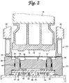
- the welded blank 14 is secured in position by the upper binder 20 once it reaches the end of its descending stroke and clamps the welded blank 14 between the upper binder 20 and the periphery of the second die 26 (FIGURE 2).
- the binder 20 prevents gross movement of the workpiece yet allows blank material to flow inwardly during formation.
- the first die 12 is then displaced towards the second die 26 and the floater assembly 32.
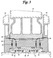
- the first die 12 contacts the welded blank 14 and displaces it relative to mated surfaces of the upper binder 20 and the second die 26, the first die 12 pushes the blank down onto the top surface of the floating component 36 of the floater assembly 32.
- This engagement forms or imparts a desired shape to the welded seam portions of the blank 14 and securely locks the welded seams 34 between the first die 12 and the floater component 36 (FIGURE 3).
- the step 37 assists in locking the welded blank in a secured position during subsequent forming.
- the biasing force and stroke of the cushion assembly must be selected appropriately in light of expected forming loads and final dimensions of the finished product.
- the cushion assembly must bias the floater component 36 with a force sufficient to deform the blank yet sufficiently less than that of the first die press that the floater component 36 will be displaced against its bias in response to continued movement of the first die 12.
- the selected biasing force must be sufficient to lock the welded portion of the welded blank to isolate stretch and formation of the heavier gauge material from stretch and formation of the lighter gauge material.
- the second die was fixed throughout the stroke of the first die, the second die could be mounted for movement relative to the first die if necessary or appropriate to the formation of the blank.
- the first die 12 is retracted to its elevated position. Thereafter, the upper binder 20 is retracted to its elevated position.
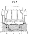
- the floater assembly 32 remains at its bottom dead center or lower limit of its stroke until the first die 12 and the upper binder 20 are completely cleared from the molded blank 14' and are in their elevated positions (FIGURE 5).
- the floater assembly is maintained at the lower limit of its stroke by locking out the die cushion in a known manner so that no power or biasing force is transmitted to floater assembly 32.
- the biasing action of the cushion assembly is reengaged following a time delay to allow sufficient time for the upper binder 20 and the first die 12 to retract, to avoid distortion of the formed blank.
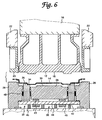
- the cushion assembly is engaged, and the floater assembly 32 is elevated to lift the formed part 14' off of the lower die 26.
- the formed part may then be removed and otherwise further processed (FIGURE 6).
- a floater assembly in accordance with the invention is incorporated in a single action press.
- the present invention is not limited to a particular configuration, and the press configurations shown are intended to illustrate the flexibility of the present invention rather than suggest any limitation.
- the first die 112 is provided now as a lower fixed die, and the die assembly 124 is disposed above the first die 112. Die assembly 124 is selectively driven towards or retracted from the workpiece 114 by the press ram 116. Again, the press ram 116 is of conventional design.
- the first die 112 is fixed to a press bed and includes the die surface 118 that imparts a desired shape to the welded blank 114.
- a blank holder 150 is mounted in surrounding relation to the first die 112 and serves the same function as a binder. Specifically, biasing cylinders 152, for example nitro cylinders, disposed below the blank holder 150 push the facing surface of the holder above the die surface 118 and provide sufficient force to clamp the blank 114 during forming. In a known manner, the blank holder 150 prevents gross movement of the blank during forming while still allowing inward material flow.
- the die assembly 124 comprises in part the second die 126 including the U-shaped space in which the positioning assembly of the second embodiment is disposed.
- the second die 126 is provided in opposed, facing relation to the first die 112 and the blank holder 150.
- the second die includes the die surface 130 that in conjunction with the first die surface 118 imparts a particular shape and configuration to a portion of the welded blank 114.
- the floater assembly 132 is defined inside of the second die 126 and is positioned to correspond to the locations of the welded seams 134 of the blank to be formed.
- the floater assembly 132 may include a single die component 136 or a plurality of such die components disposed about the periphery or inside of the second die as deemed necessary by the position of the welded seams 134.
- the blank engaging face of the floater component 136 preferably includes a step 137 to positively lock the welded portion of the blank 114 in a secured position during subsequent forming.
- the floater assembly 132 further comprises a positioning assembly 154 incorporating many of the components of the positioning assembly 38 of the first illustrated embodiment.
- the positioning assembly 154 of the second embodiment includes the plate 140 having a first side 142 and a second side 144.
- the first side 142 is in engaging relation to the floater component 136.
- the second side 144 is in engaging relation to a drive assembly 156, described more fully hereinbelow.
- Stop blocks 143 and bottoming blocks 145 are mounted to the plate 140. Those blocks are sized and serve the same function as those indicated in the description of the first illustrated embodiment. Again, it is to be appreciated that separate plates may be provided for each floater component 136.
- the drive assembly 156 serves a function similar to that of the cushion assembly.
- the drive assembly 156 includes an adapter plate 158 disposed between the press ram 116 and the second die 126.
- a plurality of drive devices 160 housed within the adapter plate 158 are engaged operatively to the plate 140.
- Suitable drive devices 160 may be, for example, hydraulic or pneumatic cylinder and piston assemblies.
- the drive devices are pneumatic cylinders.
- the particular drive devices provided in accordance with the second embodiment of the invention depend upon the desired displacement of the floater component 136 during the descending stroke of the die assembly 124 and the necessary load to lock and form the welded portion of the blank 114.
- the drive assembly 156 further includes supply lines, exhaust lines, and a storage tank (not shown in detail).
- the drive assembly 156 continually biases the floater component 136 subject to lockout.
- the pneumatic cylinders are pressurized to push the floater component 136 towards its extended position with sufficient force to form and lock the welded portion of the welded blank.
- the pneumatic cylinders can be selectively deactivated by exhausting to tank.
- the second illustrated embodiment is used to form the welded blank in a manner generally similar to the first embodiment.
- a welded blank 114 is positioned on the elevated surface of the blank holder 150 while the die assembly 124 is in its elevated position. Thereafter, the press ram 116 pushes the die assembly 124 towards the welded blank 114. Because the blank holder 150 is elevated slightly relative to the first die 112, a peripheral portion of the second die 126 clamps the blank 114 against the blank holder 150 prior to any other contact between the dies and the blank.
- the blank holder 150 retracts under the force of the second die 126, and the biasing force of the nitro cylinders 152 prevents gross movement of the blank 114 during subsequent forming. At this stage, the blank 114 contacts the die surface 118 of the first die 112.
- the pneumatic cylinders are exhausted to tank thereby unloading the biasing force of the drive devices 160.
- the die assembly 124 is retracted to its elevated position and moves relative to the floater assembly 132.
- the floater assembly 132 moves relative to the second die 126 under its weight and gently pushes the formed workpiece 114' away from the die cavity.
- FIGURE 9 is seen to be particularly advantageous when forming, for example, an automotive body panel, such as a door, because the formed part does not need to be turned over in advance of further processing, as would be the case with a press of the type shown in FIGURE 1.
- the floater assembly of the invention can advantageously be incorporated either in the upper or lower die structure of a press. This flexibility permits the advantages of the invention to be realized in a variety of part forming systems.
- the apparatus and method of the invention may be used to form metal blanks or workpieces of steel, aluminum, or any other known metal or metal alloy, or combination of metals or metal alloys.
- the apparatus and method diclosed herein, while particularly advantageously used to form blanks having portions of differing gauges, may be used to form blanks of a single guage and/or workpieces which have been previously formed at least in part.
Landscapes
- Engineering & Computer Science (AREA)
- Mechanical Engineering (AREA)
- Shaping Metal By Deep-Drawing, Or The Like (AREA)
Abstract
Description
- The present invention relates to a method and apparatus for forming blanks and, more particularly to a method and apparatus that controls stretching of metal blanks, such as multiple gauge welded blanks, during forming.
- Recent advancements in technology have provided blanks for stamping that are comprised of sheet metals of various gauges having different mechanical and chemical properties welded together to form a single welded blank. Conventional techniques used to weld the sheet metal components together include laser, induction, and mash welding. These welded blanks are of interest particularly to the automotive industry. Welded blanks can be formed into automotive body panels such that heavier gauge steel is positioned where strength is required, and lighter gauge steel is positioned where strength is less critical. Consequently, body panels formed from welded blanks provide weight reduction because heavier gauge material is provided only to those areas requiring additional strength. Additionally, welded blanks afford a reduction in the number of sheet metal components and welding operations required.
- Conventional stamping dies, however, are generally incapable of producing satisfactory products, including automotive body panels, from welded blanks. Indeed, to produce products of satisfactory quality, it is essential to deform sheet metal blanks in a uniform manner. When conventional dies are used to form welded blanks, the lighter gauge portion of the welded blank stretches before the heavier gauge portion is subject to deformation. At a minimum, such a condition causes uneven stretch of the lighter gauge material. In the worst case, conventional dies split or wrinkle the lighter gauge material of the welded blank during forming.
- It is an objective of the present invention at least in preferred embodiments thereof to provide an apparatus and method for forming blanks that uniformly deforms the blank.
- It is a further objective of the present invention at least in preferred embodiments thereof to provide an apparatus and method for forming welded blanks that prevents splitting or wrinkling of the welded blank.
- It is a yet further objective of the present invention at least in preferred embodiments thereof to provide an apparatus and method for forming welded blanks that provides unlimited and effective control over material flow during product formation from metal blanks.
- It is a further objective of the present invention at least in preferred embodiments thereof to provide an apparatus and method for forming blanks that may be adapted to a variety of configurations.
- According to the present invention in a first aspect there is provided a forming mechanism comprising: a first die member; and a second die member disposed in opposed facing relation to the first die member, at least one of the first and second die members being mounted for movement towards and away from the other die member; characterised in that the mechanism includes a floater assembly comprising at least one blank engaging component disposed adjacent to said second die member, the floater assembly being mounted for axial movement relative to the second die member; said floater assembly further comprising a support assembly for said component, said support assembly being constructed and arranged to dispose said at least one blank engaging component in a first position in which a blank engaging surface thereof is closer to said first die member than a blank engaging surface of said second die member and to permit said blank engaging component to be displaced axially from said first position upon engagement of said component by said first die during a forming stroke thereof.
- In one preferred form, the first die member is movable toward and away from the second die member and the second die member is fixed.
- The support assembly may comprise a plate having a first surface and a second surface, the first surface being in operative engagement with said component, and a biassing assembly, conveniently a spring assembly, in operative engagement with said second surface of the plate.
- It may be arranged that said spring assembly at least selectively urges said component toward said first die. Said spring assembly may comprise a plurality of cushion pins.
- In one preferred form, at least one blank engaging component is arranged so as to substantially correspond to a location and arrangement of welded seams of a blank to be formed by said first and second die members.
- The floater assembly may further comprise at least one wear plate disposed between said component and said second die.
- In another preferred form the mechanism further comprises an upper binder engageable to a periphery of said second die member for clamping and holding a peripheral edge of a blank to be formed by said first and second die members.
- Preferably, said at least one blank engaging component is disposed inside of said second die member.
- The forming mechanism may further comprise an upper binder and a lower binder for clamping and holding a peripheral edge of a blank to be formed by said first and second dies.
- It is to be appreciated that where features of the invention are set out herein with regard to apparatus according to the invention, such features may also be provided with regard to a method according to the invention, and vice versa.
- In particular, there is provided in accordance with the invention a method of forming a blank, comprising the steps of placing a metal blank in a molding apparatus intermediate a first die member and a second die member disposed in opposed facing relation to the first die member, and producing relative displacement of said first and second die members towards each other; characterised in that the molding apparatus also comprises a floater assembly comprising at least one blank engaging component disposed adjacent to said second die, the floater assembly being mounted for axial movement relative to the second die, said floater assembly having a support assembly for said component, said support assembly being constructed and arranged to dispose said at least one blank engaging component in a first position in which a blank engaging surface thereof is closer to said first die member than a blank engaging surface of said second die member and to permit said blank engaging component to be displaced axially from said first position upon engagement of said component by said first die member during a forming stroke thereof; and that the method includes the steps of: clamping a first portion of said blank between said first die member and said blank engaging component; producing relative displacement between said first die member, said blank engaging component and said first portion of said blank clamped therebetween, and said second die member, towards each other; and forming a second portion of the blank spaced from said first portion between the first die member and the second die member.
- In a preferred form the molding apparatus has a binder, and the method further comprises the step of clamping a periphery of said blank between said binder and a periphery of said second die before said step of clamping a first portion.
- The molding apparatus may have upper and lower binders, the method further comprising the step of clamping a periphery of said blank between said upper and lower binders before said step of clamping a first portion.
- In accordance with a further, independent aspect of the invention, there may be provided a method of forming a welded blank having a relatively light gauge portion, a relatively heavy gauge portion and a welded portion defined therebetween; characterised by controlling stretch of said welded blank formed by the method, by the steps of: forming said welded portion of said welded blank; locking said welded portion thereby preventing further flow of material of said welded portion; and forming remaining portions of said welded blank while the welded portion is locked.
- In accordance with a yet further, independent aspect of the invention, there may be provided a method of forming a metal blank comprising the steps of providing a metal blank having a first portion to be formed and a second portion to be formed, and forming both portions, characterised by controlling stretch of said blank by the steps of: forming said first portion of said blank; locking said first portion of said blank thereby preventing further flow of material of said first portion; and forming said second portion of said blank while the first portion is locked.
- The blank may be a steel blank. The blank may have at least one welded seam intermediate the said first and second die members. The blank may have portions of differing gauges.
- In accordance with a further, independent aspect of the invention, there may be provided a forming mechanism providing controlled stretch of a blank formed thereon, the forming mechanism comprising: a first die member; a second die member disposed in opposed facing relation to the first die member, at least one of the first die and the second die being mounted for selective movement toward and away from the other of the first die and the second die; and a floater assembly comprising at least one blank engaging component disposed adjacent to said second die, the floater assembly being mounted for axial sliding movement relative to the second die; said floater assembly further comprising a support assembly for said component, said support assembly being constructed and arranged to selectively dispose said at least one blank engaging component in a first position in which a blank engaging surface thereof is closer to said first die member than a blank engaging surface of said second die member and to permit said blank engaging component to be displaced axially from said first position upon engagement of said component by said first die during a forming stroke thereof.
- In accordance with a yet further, independent aspect of the invention, there may be provided a method for forming a blank, comprising the steps of: providing a molding apparatus comprising: a first die member; a second die member disposed in opposed facing relation to the first die member, at least one of the first die and the second die being mounted for selective movement toward and away from the other of the first die and the second die; and a floater assembly comprising at least one blank engaging component disposed adjacent to said second die, the floater assembly being mounted for axial sliding movement relative to the second die, said floater assembly having a support assembly for said component, said support assembly being constructed and arranged to selectively dispose said at least one blank engaging component in a first position in which a blank engaging surface thereof is closer to said first die member than a blank engaging surface of said second die member and to permit said blank engaging component to be displaced axially from said first position upon engagement of said component by said first die member during a forming stroke thereof; placing a metal blank intermediate said first and said second die members; displacing said first die member toward said second die member; clamping a first portion of said blank between said first die member and said blank engaging component; displacing said first die member, said blank engaging component and said first portion of said blank clamped therebetween towards said second die member; and forming a second portion of the blank spaced from said first portion between the first die member and the second die member.
- In accordance with a further, independent aspect of the invention, there may be provided a method for forming a welded blank having a relatively light gauge portion, a relatively heavy gauge portion and a welded portion defined therebetween, said method controlling stretch of said welded blank formed thereby, the method comprising the steps of: forming said welded portion of said welded blank; locking said welded portion thereby preventing further flow of material of said welded portion; and forming remaining portions of said welded blank while the welded portion is locked.
- In accordance with a yet further, independent aspect of the invention, there may be provided a method for forming a metal blank, said method controlling stretch of said blank formed thereby, the method comprising the steps of: providing a metal blank having a first portion to be formed and a second portion to be formed; forming said first portion of said blank; locking said first portion of said blank thereby preventing further flow of material of said first portion; and forming said second portion of said blank while the first portion is locked.
- Yet further preferred and optional features and combinations of features will now be described. It is particularly to be appreciated that the following statements relate only to preferred or optional or exemplary features and do not necessarily set out essential features of the invention. In some cases these features may provide independent inventive concepts which may be utilised independently of other features.
- To achieve the foregoing and other objectives of the invention, a stretch controlled forming mechanism may be provided that, in accordance with the present invention, forms and locks a first, selected portion of the blank between opposed die surfaces. In the case of a welded blank, the junction where the different gauge materials of the blank are welded together is formed and locked first. Such locking prevents continued flow of material in the locked portion during the remainder of the formation process. Thereafter, with the selected areas restricted from further material flow, the portion of the blank not previously formed is formed between the remaining opposed surfaces of the dies.
- Thus, in accordance with the present invention, a first set of opposed dies having opposed die surfaces is provided. One or all of those dies are movable relative to the others in a conventional manner. Disposed adjacent to or bounded by one of the dies of the set is a floater assembly, also having an opposed die surface. In a first embodiment of the invention, as described below, the floater assembly is disposed inwardly of the outer periphery of a lower die of the set. As one skilled in this art will appreciate after reading this description, placement of the floater is dictated by the location of the areas to be first formed and locked. In the case of a welded blank, the welded seams of the blank are to be formed and locked first. The floater assembly is mounted to a positioning assembly so as to be movable relative to the dies of the first set. In a first embodiment of the present invention, the positioning assembly is actuated or powered by a die cushion incorporated as a part of the press.
- More particularly, in a first embodiment in accordance with the principles of the invention, a first die having a die surface is provided and spaced from a second die having a die surface opposed to the first die surface. Disposed inside of the second die and slidable relative to the second die is a floater assembly that also has die surface(s) opposed to the first die surface. Again, the dies surface(s) of the floater assembly are positioned so that they will correspond to, for example, the welded areas of the blank. Thus, the floater assembly is opposed to a portion of the first die, and the second die is opposed to the remainder of the die surface of the first die.
- Prior to commencement of the forming process, the floater assembly is biased by the die cushion assembly, which is of known type, so that its die surface is ahead of that of the cavity of the second die. A blank is placed in the apparatus so that a first portion thereof, such as a portion of a welded seam, overlies a die surface of the floater assembly. Once the blank is so positioned, upper binders disposed peripherally of the first die and opposed to the periphery of the second die are displaced towards the second die to clamp and hold the blank in position. The first die is then moved towards and into contact with the floater assembly by conventional means. During this period, the cushion assembly biases the floater assembly against the first die with sufficient force to effect formation of the blank therebetween, thereby both forming and locking the first portion of the blank between the first die and the floater assembly. This biasing force, however, is insufficient to prevent the forward progress of the first die. Thus, continued movement of the first die pushes the blank and displaces the floater assembly relative to the second die. During this displacement, the first portion of the welded blank remains locked between the first die and the floater assembly. By the end of the stroke of the first die, the remaining portion(s) of the blank are formed between the first die and the second die.
- In accordance with a second embodiment of the invention the floater assembly is disposed inwardly of the outer periphery of an upper die of the press. As in the first embodiment, the floater assembly is mounted to a positioning assembly for movement relative to the upper and lower dies. In this embodiment, the positioning assembly incorporates a pneumatic or hydraulic system to bias the floater assembly to position the die surface of the floater assembly ahead of the cavity of the upper die. When the upper die and floater assembly are displaced towards the lower die, the first portion of the blank is formed and locked between the floater assembly and the lower die. Continued engagement of the floater assembly against the lower die displaces the floater assembly relative to the upper die and permits formation of the remaining portion(s) of the blank between the upper die and the lower die.
- Embodiments of the invention will now be described by way of example with reference to the accompanying drawings in which:-
- FIGURE 1 is a schematic sectional view of a stretch controlled forming apparatus provided in accordance with a first embodiment of the present invention;
- FIGURE 2 is a schematic sectional view of the apparatus of FIGURE 1 showing the binder clamping a blank in position between the binder and the periphery of the second die;
- FIGURE 3 is a schematic sectional view of the apparatus of FIGURE 1 showing the first die displaced into engagement with the floater assembly;
- FIGURE 4 is a schematic sectional view of the apparatus of FIGURE 1 showing the first die displaced into engagement with the remainder of the second die;
- FIGURE 5 is a schematic sectional view of the apparatus of FIGURE 1 showing the first die retracted after formation;
- FIGURE 6 is a schematic sectional view of the apparatus of FIGURE 1 showing the binder dies retracted after formation and the floater assembly in its elevated position; and
- FIGURE 7 is a plan view of the lower die assembly in accordance with the invention;
- FIGURE 8 is a schematic sectional view taken along line 8-8 of FIGURE 7; and
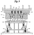
- FIGURE 9 is a schematic sectional view of a stretch controlled forming apparatus provided in accordance with a second embodiment of the present invention.
- In FIGURE 1, a first embodiment of a stretch-controlled forming mechanism in accordance with the invention, and with which the method of the invention can be carried out, is designated generally by the
reference number 10. At a minimum, the mechanism of this and other embodiments of the present invention includes three blank forming die components, one of which is opposed to the other two, which are disposed adjacent one another. As one skilled in the art will recognize after reviewing the following detailed description, any number of die components greater than three may be used. Additionally, for the sake of convenience only, the dies will be referred to by the designations first, second, etc. and one of the die components, which could be characterized as a third die, will be referred to as a floater assembly because of the manner in which it is preferably, although not necessarily, mounted. Further, for convenience, the upper die will be referred to as the first die. The apparatus and method of the present invention, however, are not limited to the particular die orientations or labels used herein, as will become apparent from the detailed description provided herein below. Thus, for example, the first die could be either the upper die or the lower die and the floater assembly could be disposed adjacent to or inside of either the upper die or the lower die. As will become clear following review of this detailed description, placement of the floater assembly is dictated by the relative location of the welded areas of the blank to be formed. - As shown in FIGURE 1, the molding apparatus embodying the principles of the present invention includes a first die which in the first illustrated embodiment is in the form of an
upper punch 12 selectively driven towards or retracted from a workpiece, for example comprising a welded blank 14, by a pressinner ram 16 which may be of conventional construction. Thefirst die 12 has adie surface 18 that, upon operative engagement, imparts a desired shape to the welded blank 14. Anupper binder 20, which is conventionally considered as a portion of thefirst die 12, is mounted in surrounding relation to thefirst die 12 and is selectively driven towards or retracted from theworkpiece 14 by a pressouter ram 22, again of conventional construction, to hold theworkpiece 14 during forming. Presses of this configuration commonly are called double action presses. As one of ordinary skill in this art will recognize, particularly following review of the description of the second embodiment, the present invention is not limited in application to double action presses. - The
molding assembly 10 further comprises alower die assembly 24 which in the first illustrated embodiment includes thesecond die 26. As best seen by reference to FIGURES 1, 7, and 8, thesecond die 26 defines roughly aU-shaped space 25 in which other assemblies, as described below, are disposed. Thesecond die 26 is provided in opposed, facing relation to thefirst die 12, andupper binder 20. Thesecond die 26 has adie surface 30 that in conjunction with thefirst die surface 18 imparts a particular shape and configuration to a portion of the welded blank 14. - As shown in FIGURE 1, the first embodiment of the present invention includes a fixed second die 26 having the
U-shaped space 25 and afirst die 12 that can be selectively displaced toward and away from the second die. The present invention, of course, only requires relative movement between the first and second dies. Thus, either or both of the dies may be movable. - In accordance with the invention, a
floater assembly 32 is positioned to correspond to the locations of weldedseams 34 of the blank to be formed. In the first exemplary embodiment illustrated in FIGURES 1-8, thefloater assembly 32 is defined inside of thesecond die 26 so as to correspond to the location(s) of weldedseams 34 in the welded blank 14. Thefloater assembly 32 may be in the form of asingle die component 36 mounted inside of the second die. Alternatively, thefloater assembly 32 may be comprised of a plurality ofdie components 36 suitably disposed about the periphery or inside of the second die as deemed appropriate or necessary to correspond to the location of the weldedseams 34 of the welded blank 14 to be formed in themolding apparatus 10. While such variations will be apparent to one skilled in this art upon review of this disclosure, the first illustrated embodiment contemplates a floater assembly comprising floater diecomponents 36 disposed inside of a second die and the description hereinbelow will be directed to that embodiment. - The
floater assembly 32 comprises at least onedie component 36, as noted above, hereinafter referred to in the singular as afloater component 36. In the first illustrated embodiment, thedie component 36 is mounted slidably in a vertical portion of theU-shaped space 25 defined by thesecond die 26. It is also to be noted that in this embodiment, the blank engaging face of the floater component has astep 37 defined on the die surface thereof to lock both the light and heavy gauge sheets of the blank in a secured position during subsequent forming. - The
floater assembly 32 further comprises apositioning assembly 38 for supporting thefloater component 36 relative to thesecond die 26. In the first illustrated embodiment, thepositioning assembly 38 includes asupport plate 40 having afirst side 42 and asecond side 44. Thefirst side 42 of theplate 40 is in supporting relation to thefloater component 36. Thesecond side 44 of theplate 40 is supported relative to thesecond die 26 and the press base by cushion pins 46. Stop blocks 43 are mounted to thefirst side 42, and bottomingblocks 45 are mounted to thesecond side 44. Those blocks are sized, as described more fully hereinbelow, to appropriately define the stroke of thepositioning assembly 38. In the first illustrated embodiment, asingle plate 40 supports thefloater component 36 of thefloater assembly 32. It is to be appreciated, however, thatseparate plates 40 may be provided for eachfloater component 36 of thefloater assembly 32 where more than onecomponent 36 is provided. However, to ensure simultaneous and uniform displacement of thefloater component 36 of thefloater assembly 32 the provision of a single continuous plate structure is currently envisioned to be most desirable. TheU-shaped space 25 accommodates such a common plate. - The cushion pins 46 may be steel rods approximately 1.5 inches in diameter that extend through pin holes in the base of the press and transmit force from the die cushion assembly (not shown) to the floater plate and hence to the
floater component 36. Die cushion assemblies are conventional mechanisms provided to supply power to presses so equipped. For example, cushion assemblies are used to lift, through pins, a workpiece from a die cavity following formation. - In the first illustrated embodiment, the cushion pins 46 are provided through pin holes such that sufficient support is provided for and force is applied to the
floater component 36. For example, the pins may be disposed every six inches over the area of theplate 40. Generally, thefloater component 36 is biased continually by the cushion assembly subject to lockout, as described more fully hereinbelow. - The force with which the floater component is biased and the displacement of the floater assembly relative to the cavity of the second die, i.e. the stroke of the
floater component 36 depends on that deemed necessary or desirable to form the blank at the weld seam and to lock it during subsequent forming, the characteristics of the weld blank, the part being formed, etc. It is anticipated that optimum displacement and force values will be best determined by try-out. - As noted above, specific values for the aforementioned parameters are dictated necessarily, of course, by the design considerations presented by particular applications, and therefore, no preferred values are suggested. Orders of magnitude for those parameters observed by the inventor during experimentation, however, likely will prove typical. In one case, satisfactory results were achieved when the
inner ram 16 was a 500 ton press, theouter ram 22 was an 80 ton press, the bias force of the cushion assembly was set at 19 tons, and the cushion travel was limited to 1 3/4 inches. In another case, satisfactory results were achieved when theinner ram 16 was a 1,200 ton press, theouter ram 22 was an 90 ton press, the bias force of the cushion assembly was set at 25 tons, and the cushion travel was limited to 60 mm. - A mechanism other than a conventional die cushion for biasing the
floater component 36 may be provided in addition or in the alternative where appropriate, as will be readily evident upon review of the description of the second embodiment, including hydraulic pistons operatively engaged in hydraulic cylinders, pneumatic cylinders, and other known resilient/biasing support structures. - Wear
plates 48 are suitably disposed intermediate thefloater assembly 32 and each side of the vertical portion of theU-shaped space 25 of thesecond die 26. The wear plate(s) 48 ensure there will be smooth, low friction, axial sliding movement of thefloater assembly 32 relative to the structures adjacent thereto without undue component wear. - While in the illustrated embodiment the
floater assembly 32 is provided so as to be selectively displaced relative to thesecond die 26, it is to be understood that depending upon the shape to be imparted to the welded blank 14, and other considerations, it may be deemed advantageous or desirable to provide an assembly in which the so called floater assembly is in fact fixed and the second die is mounted for selective displacement towards the first die to impart the desired shape to the metal blank following engagement of the welded seams by the floater assembly and first die. Thus, while the first illustrated embodiment contemplates a fixed second die and a shiftable floater assembly the invention is not deemed to be limited to that particular configuration. - In use, a welded blank 14 is positioned on the top of the
lower die assembly 24 while thefirst die 12 andupper binder 20 are disposed in their elevated positions (FIGURE 1). The welded blank 14 is secured in position by theupper binder 20 once it reaches the end of its descending stroke and clamps the welded blank 14 between theupper binder 20 and the periphery of the second die 26 (FIGURE 2). Once clamped and in a conventional manner, thebinder 20 prevents gross movement of the workpiece yet allows blank material to flow inwardly during formation. - The
first die 12 is then displaced towards thesecond die 26 and thefloater assembly 32. As the first die 12 contacts the welded blank 14 and displaces it relative to mated surfaces of theupper binder 20 and thesecond die 26, thefirst die 12 pushes the blank down onto the top surface of the floatingcomponent 36 of thefloater assembly 32. This engagement forms or imparts a desired shape to the welded seam portions of the blank 14 and securely locks the weldedseams 34 between thefirst die 12 and the floater component 36 (FIGURE 3). As noted above, thestep 37 assists in locking the welded blank in a secured position during subsequent forming. - To properly form and lock the welded portion of the welded blank, the biasing force and stroke of the cushion assembly must be selected appropriately in light of expected forming loads and final dimensions of the finished product. At a minimum, the cushion assembly must bias the
floater component 36 with a force sufficient to deform the blank yet sufficiently less than that of the first die press that thefloater component 36 will be displaced against its bias in response to continued movement of thefirst die 12. Further, the selected biasing force must be sufficient to lock the welded portion of the welded blank to isolate stretch and formation of the heavier gauge material from stretch and formation of the lighter gauge material. - Following forming and locking of the welded portion of the welded blank 14, continued downward motion of the
first die 12 displaces thefloater assembly 32 downwardly relative to thesecond die 26 and allows thedie surface 18 of thefirst die 12 and thedie surface 30 of thesecond die 26 to form the remainder of the blank (FIGURE 4). Thus, at the end of the descending stroke of thefirst die 12, forming of the blank 14 has been substantially completed. Because the welded seam(s) 34 were clamped and locked between thefirst die 12 and thefloater assembly 32 in advance of formation of the remainder of the blank, no cracks or splits are generated in the thinner sheet material near the joint. - As is apparent, and as was noted above, although in the illustrated embodiment the second die was fixed throughout the stroke of the first die, the second die could be mounted for movement relative to the first die if necessary or appropriate to the formation of the blank.
- Following blank formation, the
first die 12 is retracted to its elevated position. Thereafter, theupper binder 20 is retracted to its elevated position. However, thefloater assembly 32 remains at its bottom dead center or lower limit of its stroke until thefirst die 12 and theupper binder 20 are completely cleared from the molded blank 14' and are in their elevated positions (FIGURE 5). The floater assembly is maintained at the lower limit of its stroke by locking out the die cushion in a known manner so that no power or biasing force is transmitted tofloater assembly 32. The biasing action of the cushion assembly is reengaged following a time delay to allow sufficient time for theupper binder 20 and thefirst die 12 to retract, to avoid distortion of the formed blank. - After the
upper binder 20 is retracted to its elevated position and the time delay expires, the cushion assembly is engaged, and thefloater assembly 32 is elevated to lift the formed part 14' off of thelower die 26. The formed part may then be removed and otherwise further processed (FIGURE 6). - As noted above, some presses are not equipped with die cushion assemblies. In such apparatus or when use of the die cushion is impractical or undesirable, a hydraulic or pneumatic system may be provided to bias the floater assembly. Such an alternative system is schematically illustrated in the embodiment of FIGURE 9, which is described herein below.
- In the second embodiment, a floater assembly in accordance with the invention is incorporated in a single action press. As noted above, however, the present invention is not limited to a particular configuration, and the press configurations shown are intended to illustrate the flexibility of the present invention rather than suggest any limitation.
- In the second illustrated embodiment, the
first die 112 is provided now as a lower fixed die, and thedie assembly 124 is disposed above thefirst die 112. Dieassembly 124 is selectively driven towards or retracted from theworkpiece 114 by thepress ram 116. Again, thepress ram 116 is of conventional design. - The
first die 112 is fixed to a press bed and includes thedie surface 118 that imparts a desired shape to the welded blank 114. Ablank holder 150 is mounted in surrounding relation to thefirst die 112 and serves the same function as a binder. Specifically, biasingcylinders 152, for example nitro cylinders, disposed below theblank holder 150 push the facing surface of the holder above thedie surface 118 and provide sufficient force to clamp the blank 114 during forming. In a known manner, theblank holder 150 prevents gross movement of the blank during forming while still allowing inward material flow. - The
die assembly 124 comprises in part thesecond die 126 including the U-shaped space in which the positioning assembly of the second embodiment is disposed. Thesecond die 126 is provided in opposed, facing relation to thefirst die 112 and theblank holder 150. The second die includes thedie surface 130 that in conjunction with thefirst die surface 118 imparts a particular shape and configuration to a portion of the welded blank 114. - The
floater assembly 132 is defined inside of thesecond die 126 and is positioned to correspond to the locations of the weldedseams 134 of the blank to be formed. As was noted above with respect to the first embodiment, and remains true in this exemplary embodiment, thefloater assembly 132 may include asingle die component 136 or a plurality of such die components disposed about the periphery or inside of the second die as deemed necessary by the position of the welded seams 134. As with the first embodiment, the blank engaging face of thefloater component 136 preferably includes a step 137 to positively lock the welded portion of the blank 114 in a secured position during subsequent forming. - The
floater assembly 132 further comprises apositioning assembly 154 incorporating many of the components of thepositioning assembly 38 of the first illustrated embodiment. Thepositioning assembly 154 of the second embodiment includes theplate 140 having afirst side 142 and asecond side 144. Thefirst side 142 is in engaging relation to thefloater component 136. Thesecond side 144 is in engaging relation to adrive assembly 156, described more fully hereinbelow. Stop blocks 143 and bottomingblocks 145 are mounted to theplate 140. Those blocks are sized and serve the same function as those indicated in the description of the first illustrated embodiment. Again, it is to be appreciated that separate plates may be provided for eachfloater component 136. - In the second illustrated embodiment, the
drive assembly 156 serves a function similar to that of the cushion assembly. Thedrive assembly 156 includes anadapter plate 158 disposed between thepress ram 116 and thesecond die 126. A plurality ofdrive devices 160 housed within theadapter plate 158 are engaged operatively to theplate 140.Suitable drive devices 160 may be, for example, hydraulic or pneumatic cylinder and piston assemblies. For this illustrated embodiment, the drive devices are pneumatic cylinders. Notwithstanding the illustrated structure, the particular drive devices provided in accordance with the second embodiment of the invention depend upon the desired displacement of thefloater component 136 during the descending stroke of thedie assembly 124 and the necessary load to lock and form the welded portion of the blank 114. - The
drive assembly 156 further includes supply lines, exhaust lines, and a storage tank (not shown in detail). Thedrive assembly 156 continually biases thefloater component 136 subject to lockout. During formation, the pneumatic cylinders are pressurized to push thefloater component 136 towards its extended position with sufficient force to form and lock the welded portion of the welded blank. When required, as described below, the pneumatic cylinders can be selectively deactivated by exhausting to tank. - The second illustrated embodiment is used to form the welded blank in a manner generally similar to the first embodiment. A welded blank 114 is positioned on the elevated surface of the
blank holder 150 while thedie assembly 124 is in its elevated position. Thereafter, thepress ram 116 pushes thedie assembly 124 towards the welded blank 114. Because theblank holder 150 is elevated slightly relative to thefirst die 112, a peripheral portion of thesecond die 126 clamps the blank 114 against theblank holder 150 prior to any other contact between the dies and the blank. Theblank holder 150 retracts under the force of thesecond die 126, and the biasing force of thenitro cylinders 152 prevents gross movement of the blank 114 during subsequent forming. At this stage, the blank 114 contacts thedie surface 118 of thefirst die 112. - Continued downward motion of the
die assembly 124 displaces theblank holder 150 and brings thefloater component 136 into contact with the welded portion of the welded blank 114. This engagement forms the welded portion of the blank 114 and securely locks that portion between thefloater component 136 and thefirst die 112. The discussion of required forces and displacements in regard to the first illustrated embodiment is generally applicable here, and therefore, is not repeated. - Following forming and locking of the welded portion of the welded blank 114, continued downward motion of the
die assembly 124 displaces thefloater component 136 against the biasing action of the pneumatic cylinders and allows thedie surface 130 of thesecond die 126 and thedie surface 118 of thefirst die 112 to form the remainder of the blank. Again, because the weldedseam 134 was locked between thefirst die 112 and thefloater component 136 prior to formation of the remainder of the blank, no wrinkling or splitting occurs. - Following formation, the pneumatic cylinders are exhausted to tank thereby unloading the biasing force of the
drive devices 160. Thereafter, thedie assembly 124 is retracted to its elevated position and moves relative to thefloater assembly 132. Thefloater assembly 132 moves relative to thesecond die 126 under its weight and gently pushes the formed workpiece 114' away from the die cavity. - It should be noted that the embodiment of FIGURE 9 is seen to be particularly advantageous when forming, for example, an automotive body panel, such as a door, because the formed part does not need to be turned over in advance of further processing, as would be the case with a press of the type shown in FIGURE 1.
- Indeed, as is apparent from the foregoing, the floater assembly of the invention can advantageously be incorporated either in the upper or lower die structure of a press. This flexibility permits the advantages of the invention to be realized in a variety of part forming systems.
- As is also apparent from the foregoing, the apparatus and method of the invention may be used to form metal blanks or workpieces of steel, aluminum, or any other known metal or metal alloy, or combination of metals or metal alloys. Moreover, the apparatus and method diclosed herein, while particularly advantageously used to form blanks having portions of differing gauges, may be used to form blanks of a single guage and/or workpieces which have been previously formed at least in part.
- Thus, while the invention has been described in connection with the preferred embodiments, it should be understood readily that the present invention is not limited to the disclosed embodiments. Rather, the present invention is intended to cover various equivalent arrangements and methods included within the scope of the appended claims.
Claims (13)
- A forming mechanism comprising:
a first die member (12, 112); and
a second die member (26, 126) disposed in opposed facing relation to the first die member, at least one of the first and second die members being mounted for movement towards and away from the other die member;
characterised in that the mechanism includes a floater assembly (32, 132) comprising at least one blank engaging component (36, 136) disposed adjacent to said second die member (26, 126), the floater assembly being mounted for axial movement relative to the second die member;
said floater assembly further comprising a support assembly for said component (36, 136), said support assembly being constructed and arranged to dispose said at least one blank engaging component (36, 136) in a first position in which a blank engaging surface thereof is closer to said first die member (12, 112) than a blank engaging surface of said second die member (26, 126) and to permit said blank engaging component (32, 132) to be displaced axially from said first position upon engagement of said component (32, 132) by said first die (112) during a forming stroke thereof. - A forming mechanism according to claim 1, wherein the first die member is movable toward and away from the second die member and the second die member is fixed.
- A forming mechanism according to claim 1 or 2, wherein the support assembly comprises a plate (40, 140) having a first surface (42, 142) and a second surface (44, 144), the first surface being in operative engagement with said component, and a biassing assembly in operative engagement with said second surface of the plate.
- A forming mechanism according to claim 3, wherein said biassing assembly comprises a spring assembly comprising a plurality of cushion pins.
- A forming mechanism according to any preceding claim wherein at least one blank engaging component (36, 136) is arranged so as to substantially correspond to a location and arrangement of welded seams of a blank to be formed by said first and second die members.
- A forming mechanism according to any preceding claim further comprising an upper binder (20) engageable to a periphery of said second die member for clamping and holding a peripheral edge of a blank to be formed by said first and second die members.
- A forming mechanism according to any preceding claim wherein said at least one blank engaging component (36, 136) is disposed inside of said second die member (26, 126).
- A method of forming a blank, comprising the steps of placing a metal blank (14, 114) in a molding apparatus intermediate a first die member (12, 112) and a second die member (26, 126) disposed in opposed facing relation to the first die member, and producing relative displacement of said first and second die members towards each other;
characterised in that the molding apparatus also comprises a floater assembly comprising at least one blank engaging component (36, 136) disposed adjacent to said second die, the floater assembly being mounted for axial movement relative to the second die, said floater assembly having a support assembly for said component, said support assembly being constructed and arranged to dispose said at least one blank engaging component (36, 136) in a first position in which a blank engaging surface thereof is closer to said first die member than a blank engaging surface of said second die member and to permit said blank engaging component to be displaced axially from said first position upon engagement of said component by said first die member during a forming stroke thereof; and that the method includes the steps of:
clamping a first portion of said blank (14, 114) between said first die member (12, 112) and said blank engaging component (36, 136);
producing relative displacement between said first die member, said blank engaging component and said first portion of said blank clamped therebetween, and said second die member (26, 126), towards each other; and
forming a second portion of the blank (14, 114) spaced from said first portion between the first die member and the second die member. - A method as in claim 8, wherein the molding apparatus has an binder, and the method further comprises the step of clamping a periphery of said blank between said binder and a periphery of said second die before said step of clamping a first portion.
- A method of forming a welded blank having a relatively light gauge portion, a relatively heavy gauge portion and a welded portion defined therebetween;
characterised by controlling stretch of said welded blank formed by the method, by the steps of:
forming said welded portion of said welded blank (14, 114);
locking said welded portion thereby preventing further flow of material of said welded portion; and
forming remaining portions of said welded blank while the welded portion is locked. - A method of forming a metal blank comprising the steps of providing a metal blank (14, 114) having a first portion to be formed and a second portion to be formed and forming both portions,
characterised by controlling stretch of said blank by the steps of:
forming said first portion of said blank;
locking said first portion of said blank thereby preventing further flow of material of said first portion; and
forming said second portion of said blank while the first portion is locked. - A method according to claim 8, 9, 10 or 11 wherein said blank (14, 114) has at least one welded seam (34, 134) intermediate said first and said second die members.
- A method according to any of claims 8 to 12 wherein said blank (14, 114) has portions of differing gauges.
Priority Applications (7)
| Application Number | Priority Date | Filing Date | Title |
|---|---|---|---|
| AU40265/95A AU681982B2 (en) | 1995-02-10 | 1995-12-06 | Stretch controlled forming mechanism and method for forming multiple guage welded blanks |
| CA 2164999 CA2164999C (en) | 1995-02-10 | 1995-12-12 | Stretch controlled forming mechanism and method for forming metal blanks |
| AR33480795A AR000547A1 (en) | 1995-02-10 | 1995-12-26 | Forming mechanism and method to form an initial piece |
| CN96100633A CN1060692C (en) | 1995-02-10 | 1996-01-08 | Stretch controlled forming mechanism and method for forming metal blanks |
| JP8046820A JPH091254A (en) | 1995-02-10 | 1996-02-09 | Stretch control molding device and metal semiprocessed product molding method |
| BR9600369A BR9600369A (en) | 1995-02-10 | 1996-02-09 | Shaping mechanism and process for shaping a shape |
| KR1019960003248A KR100236867B1 (en) | 1995-02-10 | 1996-02-10 | Stretch controlled forming mechanism and method for forming multiple gauge welded blanks |
Applications Claiming Priority (2)
| Application Number | Priority Date | Filing Date | Title |
|---|---|---|---|
| US08/387,418 US5600991A (en) | 1995-02-10 | 1995-02-10 | Stretch controlled forming mechanism and method for forming multiple gauge welded blanks |
| US387418 | 1995-02-10 |
Publications (2)
| Publication Number | Publication Date |
|---|---|
| EP0726105A1 true EP0726105A1 (en) | 1996-08-14 |
| EP0726105B1 EP0726105B1 (en) | 2003-07-09 |
Family
ID=23529781
Family Applications (1)
| Application Number | Title | Priority Date | Filing Date |
|---|---|---|---|
| EP95303210A Expired - Lifetime EP0726105B1 (en) | 1995-02-10 | 1995-05-12 | Mechanism and method for forming blanks |
Country Status (7)
| Country | Link |
|---|---|
| US (1) | US5600991A (en) |
| EP (1) | EP0726105B1 (en) |
| KR (1) | KR100236867B1 (en) |
| DE (1) | DE69531233T2 (en) |
| ES (1) | ES2202340T3 (en) |
| TW (1) | TW259730B (en) |
| ZA (1) | ZA96887B (en) |
Cited By (6)
| Publication number | Priority date | Publication date | Assignee | Title |
|---|---|---|---|---|
| EP1854565A1 (en) * | 2005-02-28 | 2007-11-14 | Toyota Jidosha Kabushiki Kaisha | Press molding apparatus and press molding method |
| DE102004058191B4 (en) * | 2003-12-03 | 2011-01-27 | Honda Motor Co., Ltd. | Press molding process for metal separators for fuel cells |
| EP3178580A1 (en) * | 2015-12-11 | 2017-06-14 | Bora S.r.l. | Progressive die that allows to localize and control of the stretching of a sheet steel during forming of a brake plate |
| US20180093313A1 (en) * | 2016-04-20 | 2018-04-05 | Shenzhen China Star Optoelectronics Technology Co., Ltd. | Backplate molding devices and methods for curved displays |
| FR3095358A1 (en) * | 2019-04-24 | 2020-10-30 | Psa Automobiles Sa | METAL PLATE PRESS, WITH MECHANICAL LOCKING PIECE |
| EP4035789A4 (en) * | 2019-09-24 | 2023-03-01 | Nippon Steel Corporation | Method for manufacturing press-formed article, press-formed article, and press-forming device |
Families Citing this family (39)
| Publication number | Priority date | Publication date | Assignee | Title |
|---|---|---|---|---|
| US5941110A (en) * | 1997-05-12 | 1999-08-24 | Northern University | Adaptive method and apparatus for forming tailor welded blanks |
| ATE221423T1 (en) * | 1997-09-18 | 2002-08-15 | Cosma Int Inc | STRETCHING AND DRAWING TOOL AND ASSOCIATED METHOD |
| US6032504A (en) * | 1997-10-16 | 2000-03-07 | Cosma International Inc. | Draw stamping die for stamping body panels for motor vehicles |
| AUPQ052199A0 (en) * | 1999-05-21 | 1999-06-17 | Wiltin Pty Ltd | Joining arrangements for structural members |
| JP3330921B2 (en) * | 2000-03-13 | 2002-10-07 | 菊池プレス工業株式会社 | Tailored blank articles and method for producing the same |
| US6550124B2 (en) * | 2001-06-29 | 2003-04-22 | General Motors Corporation | Method for adhering reinforcing patches during superplastic forming |
| DE10233008A1 (en) * | 2002-07-20 | 2004-02-12 | Nothelfer Gmbh | Process for material flow control when deep-drawing sheet metal and deep-drawing tool |
| US7578223B2 (en) * | 2003-03-10 | 2009-08-25 | Superior Cam, Inc. | Modular die press assembly |
| US7096557B2 (en) * | 2004-06-24 | 2006-08-29 | General Motors Corporation | Making panel reinforcements during hot stretch forming |
| US7237423B1 (en) | 2004-11-12 | 2007-07-03 | Miller Tool And Die Company Inc. | Apparatus for stretch forming blanks |
| US20060283130A1 (en) * | 2005-06-07 | 2006-12-21 | William Andrews | Structural members with gripping features and joining arrangements therefor |
| JP2007098443A (en) * | 2005-10-05 | 2007-04-19 | Toyota Motor Corp | Press forming method and press forming apparatus |
| US7594331B2 (en) * | 2005-11-05 | 2009-09-29 | Wiltin Pty. Ltd. | Method of production of joining profiles for structural members |
| US20090293405A1 (en) * | 2005-11-05 | 2009-12-03 | Andrews William J | Method of production of joining profiles for structural members |
| US20070209306A1 (en) * | 2006-03-08 | 2007-09-13 | Trakloc International, Llc | Fire rated wall structure |
| JP2007268608A (en) * | 2006-03-08 | 2007-10-18 | Kobe Steel Ltd | Press-forming method of aluminum alloy sheet and press device |
| US8429946B2 (en) * | 2006-10-17 | 2013-04-30 | Honda Motor Co., Ltd. | Press-working method, and press-working apparatus |
| US8062763B2 (en) * | 2007-02-28 | 2011-11-22 | Shiloh Industries, Inc. | Metal blank with binder trim component |
| US20090158580A1 (en) * | 2007-06-18 | 2009-06-25 | Precision Valve Corporation | Method of making aerosol valve mounting cups and resultant cups |
| US8118197B2 (en) * | 2007-06-18 | 2012-02-21 | Precision Valve Corporation | Method of making aerosol valve mounting cups and resultant cups |
| KR100907683B1 (en) | 2007-11-12 | 2009-07-13 | 현대하이스코 주식회사 | Press shaping device for shaping metal sheet using movable-type binder |
| JP4781380B2 (en) * | 2008-03-28 | 2011-09-28 | 豊臣機工株式会社 | Press working apparatus and press working method |
| CN102176988B (en) * | 2008-10-07 | 2013-05-15 | 新日铁住金株式会社 | Metallic press-formed piece crack determining method, apparatus, program and recording medium |
| US8061099B2 (en) * | 2009-05-19 | 2011-11-22 | Tsf Systems, Llc | Vertical deflection extension end member |
| JP5416498B2 (en) * | 2009-07-23 | 2014-02-12 | 本田技研工業株式会社 | Method and apparatus for forming tailored blank plate |
| DE102010023001A1 (en) * | 2010-04-27 | 2011-10-27 | Läpple Werkzeugbau GmbH | Tool for drawing sheet, particularly for shaping with small radii, particularly for manufacturing of automotive-mold parts, has die and stamp, where sheet is shaped between die and stamp corresponding to contour of die and stamp |
| KR20120062273A (en) * | 2010-12-06 | 2012-06-14 | 현대자동차주식회사 | Press system |
| US9149854B2 (en) | 2011-05-04 | 2015-10-06 | Fca Us Llc | Stamping apparatus |
| US20130042450A1 (en) * | 2011-08-15 | 2013-02-21 | Hans R. Bergkvist | Apparatus for joining two or more overlapping material members and method for manufacturing of the apparatus |
| HK1181962A2 (en) * | 2012-09-27 | 2013-11-15 | Gainteam Holdings Ltd | A metal forming head, a machine with such a head and a metal forming method |
| US8919177B2 (en) * | 2013-03-13 | 2014-12-30 | Tyco Electronics Corporation | Movable die component for a press device |
| CN105682819B (en) * | 2013-09-24 | 2017-10-13 | 新日铁住金株式会社 | The manufacture device of Cap-style Section part |
| US9044801B2 (en) * | 2013-10-21 | 2015-06-02 | Ford Global Technologies, Llc | Deep draw manufacturing process |
| CN105312815A (en) * | 2015-11-16 | 2016-02-10 | 大明重工有限公司 | Boat deck assembling tool |
| US10898938B2 (en) * | 2016-03-16 | 2021-01-26 | Nippon Steel Corporation | Method for manufacturing panel-like formed article |
| KR102032185B1 (en) | 2016-03-23 | 2019-10-15 | 닛폰세이테츠 가부시키가이샤 | Door inner panel and door inner panel manufacturing method |
| DE102016005902B3 (en) * | 2016-05-13 | 2017-06-29 | Audi Ag | Method and press tool for producing a complex sheet metal part with high draw depth |
| JP7272925B2 (en) * | 2019-10-10 | 2023-05-12 | 株式会社神戸製鋼所 | Automotive panel manufacturing method |
| CN111922169A (en) * | 2020-08-10 | 2020-11-13 | 华人运通(江苏)技术有限公司 | Method for processing vehicle door |
Citations (3)
| Publication number | Priority date | Publication date | Assignee | Title |
|---|---|---|---|---|
| FR702089A (en) * | 1929-07-02 | 1931-03-28 | Budd Edward G Mfg Co | Improvements to metal sheets or sheets and their manufacturing process |
| DE2450624A1 (en) * | 1973-10-30 | 1975-05-07 | Raciborska Fabryka Kotlow Rafa | DEVICE FOR PRESSING DEEP, THIN-WALLED CONTAINER FLOORS WITH LARGE DIAMETERS |
| DE4104256A1 (en) * | 1991-02-13 | 1992-08-20 | Thyssen Laser Technik Gmbh | Deep drawn article esp. automobile body part mfr. - using sheet made by laser welding inner and outer sheet portions |
Family Cites Families (8)
| Publication number | Priority date | Publication date | Assignee | Title |
|---|---|---|---|---|
| US798530A (en) * | 1903-07-11 | 1905-08-29 | Can And Mfg Company Of Delaware Bureau | Die-punching apparatus. |
| US1898883A (en) * | 1930-07-26 | 1933-02-21 | Company Union Guardian Trust | Method of stamping front one-piece automobile fenders |
| US2112653A (en) * | 1934-03-26 | 1938-03-29 | Kelsey Hayes Wheel Co | Method of forming brake drums |
| US2689539A (en) * | 1949-02-05 | 1954-09-21 | Lyon George Albert | Apparatus for making wheel covers |
| BE792036A (en) * | 1971-11-29 | 1973-05-29 | Caterpillar Tractor Co | METHOD AND APPARATUS FOR DEFORMING SHEET MATERIAL |
| JPS6011574B2 (en) * | 1980-10-06 | 1985-03-27 | 日産自動車株式会社 | press equipment |
| EP0186016B1 (en) * | 1984-12-07 | 1991-04-17 | Sumitomo Chemical Company, Limited | A method of making a laminated body and a molding apparatus for the same |
| JPH0761506B2 (en) * | 1986-09-25 | 1995-07-05 | 本田技研工業株式会社 | Method and apparatus for drawing thin plate-like work |
-
1995
- 1995-02-10 US US08/387,418 patent/US5600991A/en not_active Expired - Lifetime
- 1995-05-12 EP EP95303210A patent/EP0726105B1/en not_active Expired - Lifetime
- 1995-05-12 DE DE69531233T patent/DE69531233T2/en not_active Expired - Fee Related
- 1995-05-12 ES ES95303210T patent/ES2202340T3/en not_active Expired - Lifetime
- 1995-05-15 TW TW084104781A patent/TW259730B/en active
-
1996
- 1996-02-05 ZA ZA96887A patent/ZA96887B/en unknown
- 1996-02-10 KR KR1019960003248A patent/KR100236867B1/en not_active IP Right Cessation
Patent Citations (3)
| Publication number | Priority date | Publication date | Assignee | Title |
|---|---|---|---|---|
| FR702089A (en) * | 1929-07-02 | 1931-03-28 | Budd Edward G Mfg Co | Improvements to metal sheets or sheets and their manufacturing process |
| DE2450624A1 (en) * | 1973-10-30 | 1975-05-07 | Raciborska Fabryka Kotlow Rafa | DEVICE FOR PRESSING DEEP, THIN-WALLED CONTAINER FLOORS WITH LARGE DIAMETERS |
| DE4104256A1 (en) * | 1991-02-13 | 1992-08-20 | Thyssen Laser Technik Gmbh | Deep drawn article esp. automobile body part mfr. - using sheet made by laser welding inner and outer sheet portions |
Cited By (8)
| Publication number | Priority date | Publication date | Assignee | Title |
|---|---|---|---|---|
| DE102004058191B4 (en) * | 2003-12-03 | 2011-01-27 | Honda Motor Co., Ltd. | Press molding process for metal separators for fuel cells |
| EP1854565A1 (en) * | 2005-02-28 | 2007-11-14 | Toyota Jidosha Kabushiki Kaisha | Press molding apparatus and press molding method |
| EP1854565A4 (en) * | 2005-02-28 | 2010-09-22 | Toyota Motor Co Ltd | Press molding apparatus and press molding method |
| US8061176B2 (en) | 2005-02-28 | 2011-11-22 | Toyota Jidosha Kabushiki Kaisha | Press molding device and press molding method |
| EP3178580A1 (en) * | 2015-12-11 | 2017-06-14 | Bora S.r.l. | Progressive die that allows to localize and control of the stretching of a sheet steel during forming of a brake plate |
| US20180093313A1 (en) * | 2016-04-20 | 2018-04-05 | Shenzhen China Star Optoelectronics Technology Co., Ltd. | Backplate molding devices and methods for curved displays |
| FR3095358A1 (en) * | 2019-04-24 | 2020-10-30 | Psa Automobiles Sa | METAL PLATE PRESS, WITH MECHANICAL LOCKING PIECE |
| EP4035789A4 (en) * | 2019-09-24 | 2023-03-01 | Nippon Steel Corporation | Method for manufacturing press-formed article, press-formed article, and press-forming device |
Also Published As
| Publication number | Publication date |
|---|---|
| TW259730B (en) | 1995-10-11 |
| DE69531233D1 (en) | 2003-08-14 |
| DE69531233T2 (en) | 2004-04-22 |
| KR100236867B1 (en) | 2000-01-15 |
| ES2202340T3 (en) | 2004-04-01 |
| US5600991A (en) | 1997-02-11 |
| EP0726105B1 (en) | 2003-07-09 |
| KR960031009A (en) | 1996-09-17 |
| ZA96887B (en) | 1996-10-16 |
Similar Documents
| Publication | Publication Date | Title |
|---|---|---|
| EP0726105B1 (en) | Mechanism and method for forming blanks | |
| CA2164999C (en) | Stretch controlled forming mechanism and method for forming metal blanks | |
| CA2147915C (en) | Automated dimpling apparatus | |
| US5247862A (en) | Process for producing burr-free workpieces by blanking, in particular in a counterblanking tool | |
| US5941110A (en) | Adaptive method and apparatus for forming tailor welded blanks | |
| EP2032277B1 (en) | Shell press and method for forming a shell | |
| KR101555968B1 (en) | Bending machine for pipe | |
| US4036056A (en) | Single-slide press for carrying out multiple functions with a single work-input stroke | |
| US20020078730A1 (en) | Electric hemming press | |
| US20180133774A1 (en) | System and method for bending metal including tandem press brakes | |
| CA3080350C (en) | Fine blanking system and method for operating the same | |
| EP1340557A2 (en) | Method for removing strain from press-formed workpiece, and forming press | |
| US7155949B2 (en) | Fluid cell press with a gripping arrangement and method and use of the press | |
| US20020038563A1 (en) | Forming equipment for rolling and profiling disk-shaped and ring-shaped parts | |
| CN105899307B (en) | For forming the device of sheet metal work piece | |
| US6889535B1 (en) | Tool assembly | |
| JP3378491B2 (en) | Forging press for irregular long products | |
| JP2013150991A (en) | Tube material molding apparatus and method | |
| CN212370964U (en) | Hydraulic press for precision forming of brake pad steel backing | |
| JPH0824982A (en) | Production of al alloy forged product and forging press apparatus thereof | |
| CN1064280C (en) | Forming press having elastic matrix | |
| JPH11188450A (en) | Forging press for deformed long article | |
| JPS6114026A (en) | Die cushion device | |
| JP2003513801A (en) | Deep drawing press and method for deep drawing of sheet metal workpiece | |
| JPH0970698A (en) | Device for drawing steel sheet and sheet continuos machining equipment utilizing above |
Legal Events
| Date | Code | Title | Description |
|---|---|---|---|
| PUAI | Public reference made under article 153(3) epc to a published international application that has entered the european phase |
Free format text: ORIGINAL CODE: 0009012 |
|
| AK | Designated contracting states |
Kind code of ref document: A1 Designated state(s): DE ES FR GB IT SE |
|
| 17P | Request for examination filed |
Effective date: 19961030 |
|
| 17Q | First examination report despatched |
Effective date: 20000330 |
|
| GRAH | Despatch of communication of intention to grant a patent |
Free format text: ORIGINAL CODE: EPIDOS IGRA |
|
| GRAH | Despatch of communication of intention to grant a patent |
Free format text: ORIGINAL CODE: EPIDOS IGRA |
|
| GRAA | (expected) grant |
Free format text: ORIGINAL CODE: 0009210 |
|
| AK | Designated contracting states |
Designated state(s): DE ES FR GB IT SE |
|
| REG | Reference to a national code |
Ref country code: GB Ref legal event code: FG4D |
|
| REF | Corresponds to: |
Ref document number: 69531233 Country of ref document: DE Date of ref document: 20030814 Kind code of ref document: P |
|
| REG | Reference to a national code |
Ref country code: SE Ref legal event code: TRGR |
|
| ET | Fr: translation filed | ||
| REG | Reference to a national code |
Ref country code: ES Ref legal event code: FG2A Ref document number: 2202340 Country of ref document: ES Kind code of ref document: T3 |
|
| PLBE | No opposition filed within time limit |
Free format text: ORIGINAL CODE: 0009261 |
|
| STAA | Information on the status of an ep patent application or granted ep patent |
Free format text: STATUS: NO OPPOSITION FILED WITHIN TIME LIMIT |
|
| 26N | No opposition filed |
Effective date: 20040414 |
|
| PGFP | Annual fee paid to national office [announced via postgrant information from national office to epo] |
Ref country code: ES Payment date: 20090518 Year of fee payment: 15 |
|
| PGFP | Annual fee paid to national office [announced via postgrant information from national office to epo] |
Ref country code: SE Payment date: 20090507 Year of fee payment: 15 Ref country code: IT Payment date: 20090515 Year of fee payment: 15 Ref country code: FR Payment date: 20090507 Year of fee payment: 15 Ref country code: DE Payment date: 20090529 Year of fee payment: 15 |
|
| PGFP | Annual fee paid to national office [announced via postgrant information from national office to epo] |
Ref country code: GB Payment date: 20090407 Year of fee payment: 15 |
|
| GBPC | Gb: european patent ceased through non-payment of renewal fee |
Effective date: 20100512 |
|
| EUG | Se: european patent has lapsed | ||
| REG | Reference to a national code |
Ref country code: FR Ref legal event code: ST Effective date: 20110131 |
|
| PG25 | Lapsed in a contracting state [announced via postgrant information from national office to epo] |
Ref country code: IT Free format text: LAPSE BECAUSE OF NON-PAYMENT OF DUE FEES Effective date: 20100512 Ref country code: SE Free format text: LAPSE BECAUSE OF NON-PAYMENT OF DUE FEES Effective date: 20100513 |
|
| PG25 | Lapsed in a contracting state [announced via postgrant information from national office to epo] |
Ref country code: DE Free format text: LAPSE BECAUSE OF NON-PAYMENT OF DUE FEES Effective date: 20101201 |
|
| PG25 | Lapsed in a contracting state [announced via postgrant information from national office to epo] |
Ref country code: FR Free format text: LAPSE BECAUSE OF NON-PAYMENT OF DUE FEES Effective date: 20100531 |
|
| REG | Reference to a national code |
Ref country code: ES Ref legal event code: FD2A Effective date: 20110715 |
|
| PG25 | Lapsed in a contracting state [announced via postgrant information from national office to epo] |
Ref country code: ES Free format text: LAPSE BECAUSE OF NON-PAYMENT OF DUE FEES Effective date: 20110705 Ref country code: GB Free format text: LAPSE BECAUSE OF NON-PAYMENT OF DUE FEES Effective date: 20100512 |
|
| PG25 | Lapsed in a contracting state [announced via postgrant information from national office to epo] |
Ref country code: ES Free format text: LAPSE BECAUSE OF NON-PAYMENT OF DUE FEES Effective date: 20100513 |