EP0725904B1 - Steering Column Assembly - Google Patents
Steering Column Assembly Download PDFInfo
- Publication number
- EP0725904B1 EP0725904B1 EP94930723A EP94930723A EP0725904B1 EP 0725904 B1 EP0725904 B1 EP 0725904B1 EP 94930723 A EP94930723 A EP 94930723A EP 94930723 A EP94930723 A EP 94930723A EP 0725904 B1 EP0725904 B1 EP 0725904B1
- Authority
- EP
- European Patent Office
- Prior art keywords
- shaft
- universal joint
- angle
- axis
- yoke
- Prior art date
- Legal status (The legal status is an assumption and is not a legal conclusion. Google has not performed a legal analysis and makes no representation as to the accuracy of the status listed.)
- Expired - Lifetime
Links
- 230000008878 coupling Effects 0.000 abstract description 2
- 238000010168 coupling process Methods 0.000 abstract description 2
- 238000005859 coupling reaction Methods 0.000 abstract description 2
- 230000007246 mechanism Effects 0.000 description 16
- 239000000463 material Substances 0.000 description 3
- 238000000034 method Methods 0.000 description 3
- 238000006073 displacement reaction Methods 0.000 description 2
- 239000000314 lubricant Substances 0.000 description 2
- CWQXQMHSOZUFJS-UHFFFAOYSA-N molybdenum disulfide Chemical compound S=[Mo]=S CWQXQMHSOZUFJS-UHFFFAOYSA-N 0.000 description 2
- 229910052982 molybdenum disulfide Inorganic materials 0.000 description 2
- 230000009467 reduction Effects 0.000 description 2
- 230000008901 benefit Effects 0.000 description 1
- 238000005094 computer simulation Methods 0.000 description 1
- 230000000694 effects Effects 0.000 description 1
- 239000012530 fluid Substances 0.000 description 1
- 238000010348 incorporation Methods 0.000 description 1
- 238000004519 manufacturing process Methods 0.000 description 1
- 238000004806 packaging method and process Methods 0.000 description 1
- 230000002028 premature Effects 0.000 description 1
- 230000008569 process Effects 0.000 description 1
- 239000007787 solid Substances 0.000 description 1
Images


Classifications
-
- B—PERFORMING OPERATIONS; TRANSPORTING
- B62—LAND VEHICLES FOR TRAVELLING OTHERWISE THAN ON RAILS
- B62D—MOTOR VEHICLES; TRAILERS
- B62D1/00—Steering controls, i.e. means for initiating a change of direction of the vehicle
- B62D1/02—Steering controls, i.e. means for initiating a change of direction of the vehicle vehicle-mounted
- B62D1/16—Steering columns
-
- F—MECHANICAL ENGINEERING; LIGHTING; HEATING; WEAPONS; BLASTING
- F16—ENGINEERING ELEMENTS AND UNITS; GENERAL MEASURES FOR PRODUCING AND MAINTAINING EFFECTIVE FUNCTIONING OF MACHINES OR INSTALLATIONS; THERMAL INSULATION IN GENERAL
- F16D—COUPLINGS FOR TRANSMITTING ROTATION; CLUTCHES; BRAKES
- F16D3/00—Yielding couplings, i.e. with means permitting movement between the connected parts during the drive
- F16D3/16—Universal joints in which flexibility is produced by means of pivots or sliding or rolling connecting parts
- F16D3/26—Hooke's joints or other joints with an equivalent intermediate member to which each coupling part is pivotally or slidably connected
- F16D3/30—Hooke's joints or other joints with an equivalent intermediate member to which each coupling part is pivotally or slidably connected in which the coupling is specially adapted to constant velocity-ratio
- F16D3/32—Hooke's joints or other joints with an equivalent intermediate member to which each coupling part is pivotally or slidably connected in which the coupling is specially adapted to constant velocity-ratio by the provision of two intermediate members each having two relatively perpendicular trunnions or bearings
- F16D3/33—Hooke's joints or other joints with an equivalent intermediate member to which each coupling part is pivotally or slidably connected in which the coupling is specially adapted to constant velocity-ratio by the provision of two intermediate members each having two relatively perpendicular trunnions or bearings with ball or roller bearings
Definitions
- This invention relates to universal joints and more particularly to trunnion pin double Cardan universal joints.
- the parameters of a well designed vehicle steering system include a consistent torque effort at the steering wheel, a crisp and symmetric return to the straight ahead position, and a pleasing on-centre feel. Historically, these features were more easily attained with a straight-line placement of the steering column relative to the gear connection.
- EP-A-266 255 discloses a steering column assembly of the type which has a first, individual universal joint and a second, double cardan universal joint. This can provide an error in true constant velocity motion of the steering column assembly.
- a steering column assembly of the type having a first shaft, a second shaft, a first universal joint connecting the first shaft to the second shaft, the axis of the first shaft being at an angle ⁇ to the axis of the second shaft, a third shaft; and a double cardan universal joint connecting the second shaft to the third shaft, the double cardan universal joint comprised of two pivotal second universal joints pivotally connected by a connecting yoke, each second universal joint pivoting about an axis fixed to the connecting yoke and being perpendicular to the longitudinal axis of said yoke, said longitudinal axis extending through the points about which the second universal joints pivot, the axis of the third shaft being at an angle ⁇ to the connecting yoke axis, the axis of the second shaft being at an angle ⁇ to the connecting yoke axis, characterized in that: said pivot axis of the second universal joint is perpendicular to the pivot axis of the other second
- a steering column assembly of the type having a first shaft, a second shaft, a first universal joint connecting the first shaft to the second shaft, the axis of the first shaft being at an angle ⁇ to the axis of the second shaft, a third shaft, and a double cardan universal joint connecting the second shaft to the third shaft, the double cardan universal joint comprised of two pivotal second universal joints pivotally connected by a connecting yoke, each second universal joint pivoting about an axis fixed to the connecting yoke and being perpendicular to the longitudinal axis of said yoke, said longitudinal axis extending through the points about which the second universal joints pivot, the axis of the third shaft being at an angle ⁇ to the connecting yoke axis, the axis of the second shaft also being at an angle a to the connecting yoke axis characterized in that: the pivot axis of one second universal joint is at an angle ⁇ to the pivot axis of the other
- the present invention is a small diameter, simplified double Cardan universal joint that, unlike multiple joint, high angle, single Cardan universal joint systems, can transmit rotational motion at near constant velocity, resulting in little or no torque variation, thus approximating the performance of less complex systems of years past.
- FIG. 4 Shown in FIG. 4 is a typically steering system.
- a steering wheel 1 is connected to an upper shaft 4 which is connected by a single Cardan universal joint 5 to a middle shaft 7.
- a double Cardan universal joint 10 incorporating the present invention connects the middle shaft 7 to a lower shaft 12.
- the lower shaft 12 is then connected to a steering gear box 14.
- FIG. 1 shows an exploded perspective view of a universal joint incorporating the present invention. Shown is a trunnion pin type double Cardan universal joint 10. A circular annular cross ring 30 is used in place of the typical Cardan cross yoke. A tubular housing 20 is used in place of the typical Cardan coupling yoke. The use of the tubular housing 20 and the pair of circular annular cross rings 30 reduces the outer dimensions of the double Cardan universal joint 10 and simplifies manufacturing, thereby reducing cost.
- the double Cardan universal joint 10 is used to pivotally connect two shafts 7, 12.
- One shaft 7 has a shaft socket extension 32 attached to its end.
- the shaft socket extension 32 has a ball socket 33 in its free end.
- the other shaft 12 has a shaft ball extension 34 attached to its end.
- the shaft ball extension 34 has a centering ball 35 integral with its free end. Both shaft extensions 32, 34 have pin receiving apertures 56 therethrough.
- Each shaft extension 32, 34 is pivotally connected to a circular annular cross ring 30.
- the axes of pivot 55a, 55b of the shaft extensions 32, 34 are parallel.
- one axis of pivot 55a is rotated 90° to the other axis of pivot 55b.
- the axes of pivot of the shaft extensions 32, 34 may be orientated respectively to one another at any angle between 0° and 90°, inclusive, as shown in FIG. 7.
- Each cross ring 30 is a tubular like annular ring having a pair of opposed pin receiving apertures 60 therethrough and a pair of opposed bearing receiving apertures 58 therethrough.
- Each shaft extension 32, 34 is pivotally connected to a cross ring 30 by a pair of trunnions 43.
- Each trunnion 43 is comprised of a trunnion pin 40, a bearing 44 and a thrust collar 42.
- a pair of trunnion pins 40 are fixedly inserted into the shaft pin receiving apertures 56.
- a bearing 44 preferably a drawn cup needle bearing, is placed over an enlarged diameter portion of trunnion pin 40. The outer portion of bearing 44 is received within the cross ring bearing receiving apertures 58.
- the bearing 44 may be secured to the cross ring 30 by any of a number of known methods, such as staking.
- the thrust collar 42 is interposed between the shaft extension 32, 34 and the cross ring 30.
- the thrust collar 42 transfers thrust loads between the shaft extensions 32, 34 and the bearing 44 housing. Without the thrust collars 42, thrust loads may be imposed on the bearing 44 internals which can cause premature bearing failure.
- the thrust collar 42 is formed of a self-lubricating bearing material containing a lubricant such as molybdenum disulfide.
- the circular annular cross rings 30 are pivotally connected to a cylindrical tubular housing 20.
- the tubular housing 20 has two pair of spaced apart opposed bearing receiving apertures 62 therethrough.
- Each cross ring 30 is pivotally connected to the tubular housing 20 by a pair of trunnions 43.
- the trunnions 43 pivotally connect the circular annular cross rings 30 to the tubular housing 20 in the manner described above for the pivotal connection of the shaft extensions 32, 34 to the circular annular cross rings 30.
- the axis of pivot 50a, 50b of each cross ring 30 is at a 90° angle to the axis of pivot 55a, 55b, respectively, of each shaft extension 32, 34.
- the axes of pivot 50a and 50b are parallel.
- the double Cardan universal joint 10 is sealed by external perimeter boot seals 22 located at the ends of the cylindrical tubular housing 20. These boot seals 22 prevent debris and fluids from entering and possibly damaging the centering mechanism 37. The need for a separate centering device seal is eliminated.
- the boot seals 22 must be able to absorb both angular and torsional displacements.
- the present invention includes a centering mechanism 37, which is comprised of a centering ball 35 integral with shaft extension 34 and a corresponding socket 33 integral with shaft extension 32.
- a centering mechanism 37 formed of components integral with the shaft extensions 32, 34, the problems with fit typically found in ball and shaft stud arrangements are eliminated.
- the rotational clearance of the double Cardan universal joint is also reduced with this integral configuration.
- the socket 33 can be simply a bore machined into the end of shaft extension 32.
- An interface sleeve 38 is positioned with the socket 33 to support the ball 35 and allow the ball 35 to move axially relative to the socket 33 during joint angular changes.
- the interface sleeve 38 is cylindrical in design and can be made from a variety of materials and processes depending upon the contact stresses encountered in the centering mechanism 37.
- the interface sleeve 38 is formed of a self-lubricating bearing material containing a lubricant such as molybdenum disulfide.
- the integral shaft/centering mechanism design allows centerline distance between the cross ring pivot axes 50a, 50b to be minimized. This results in a reduction of the double Cardan universal joint 10 diametral and axial dimensions, when compared to a conventional double Cardan universal joint design.
- the centering mechanism 37 forces the intersection of the centerlines of the shaft extensions 32, 34 (and the corresponding shafts 7, 12), as shown schematically in FIG. 5.
- This type of constant velocity double Cardan universal joint operates at true constant velocity in only two positions. The first is the degenerate case of zero degrees operating angle. The second is the design operating angle ⁇ , which is a function of the axial position of the fixed portion of the centering mechanism 37 with respect to one of the two individual joints (which make up the double Cardan universal joint).
- a double Cardan universal joint operating as a true constant velocity at a 40° operating angle would have its centering mechanism positioned such that the center point 11 and the two individual U-joints pivot points 51a, 51b would form a perfect isosceles triangle.
- the two equal angles, ⁇ and ⁇ would be exactly 20°.
- the output velocity of the double Cardan universal joint exactly equals the input velocity of the double Cardan universal joint.
- the nominal design operating angle for the present double Cardan universal joint is 40°.
- the first maximum angle mechanism is a stop ring 36 provided on each shaft extension 32, 34.
- the diameter of the stop ring 36 is designed such that the stop ring 36 will engage the tubular housing 20 prior to the ball 35 disengaging from the socket 33.
- the second maximum angle mechanism comprises the shaft portion of the shaft extensions 32, 34 adjacent the stop ring 36 engaging the circular annular cross rings 30 prior to the ball 35 disengaging from the socket 33.
- the third maximum angle mechanism comprises the circular annular cross rings 30 engaging one another prior to the ball 35 disengaging from the socket 33.
- the maximum allowed angle is 50°.
- the double Cardan universal joint could still be positioned to operate at 40°, but the individual joint angles would each be slightly above and slightly below 20° respectively, giving an error in true constant velocity motion, i.e., the instantaneous output velocity would not remain numerically equal to the input velocity.
- a double Cardan universal joint can be deliberately designed to operate at a small equivalent angle which can then be phased to subtract from the other joint angle, thereby reducing or eliminating the overall system equivalent angle. This could be especially useful in a system where one of the operating angles is greater than approximately 35°, thus requiring a constant velocity joint, while the second joint operates at a high enough angle that it by itself could cause marginally "lumpy" steering.
- ⁇ system ⁇ 1 2 - ⁇ 2 2
- ⁇ 1 is the equivalent angle of the double Cardan universal joint 10
- ⁇ 2 is the angle of the single Cardan universal joint 5.
- the cross ring pivot axes 50a, 50b can be oriented relatively to one another at any angle between 0° and 90°.
- a double Cardan universal joint of the present invention operating with a total angle of 40° with the cross ring pivot axes 50a, 50b rotated between 0°and 90° will have an equivalent operating angle from 0° to 28°.
- FIG. 7 shows a tubular housing 20 with the cross ring pivot axes 50a, 50b rotated 25° relative to one another.
- FIG. 10 shows the relationship between the rotational offset of the cross ring pivot axes 50a, 50b and the resulting equivalent operating angle for a double Cardan universal joint of the present invention having a design operating angle of 40°.
- the equivalent angle ⁇ system of the three joint system is 17°.
- the cross ring pivot axes 50a, 50b are oriented 90° relative to one another, as shown in FIG. 6.
- the equivalent angle ⁇ system of the three joint system is 22.6°.
- the equivalent angle of the double Cardan universal joint 10 is approximately 16.9° and the equivalent angle ⁇ system of the three joint system is approximately 1.8°.
- the system velocity variation is essentially zero, resulting in a nearly constant velocity steering system.
- One method of determining the equivalent angle of a double Cardan universal joint 10 having rotated cross ring axes 50a, 50b is to model the double Cardan universal joint using a computational modeling system such as an Aries Solids Modeling with Mechanisms to determine the velocity versus time at a specific angle.
- FIG. 8 shows the velocity variation for a double Cardan universal joint with an actual operating angle of 40° with the cross ring axes 50a, 50b rotated 21° relative to one another. From a graph such as shown in FIG. 8, the percent variation in velocity can be determined. The graph shown in FIG. 9 converts percent variation in velocity to equivalent angle.
- the preferred equivalent angle is one which is exactly equal to the angle of the single Cardan universal joint 5 in the three joint system shown in FIG. 4 and 5. If the equivalent angle of the rotated axes double Cardan universal joint is within approximately 3° degrees of the single Cardan universal joint 5, the velocity variation of the three joint system will be essentially zero.
Landscapes
- Engineering & Computer Science (AREA)
- General Engineering & Computer Science (AREA)
- Mechanical Engineering (AREA)
- Chemical & Material Sciences (AREA)
- Combustion & Propulsion (AREA)
- Transportation (AREA)
- Steering Controls (AREA)
- Joints Allowing Movement (AREA)
- Earth Drilling (AREA)
- Pivots And Pivotal Connections (AREA)
Abstract
Description
- This invention relates to universal joints and more particularly to trunnion pin double Cardan universal joints.
- The parameters of a well designed vehicle steering system include a consistent torque effort at the steering wheel, a crisp and symmetric return to the straight ahead position, and a pleasing on-centre feel. Historically, these features were more easily attained with a straight-line placement of the steering column relative to the gear connection.
- The trend toward downsizing, along with new vehicle requirements for crush zones and tighter package restraints, have necessitated the incorporation of multiple universal joint steering systems, thus making the features of a well designed steering system more difficult to obtain. Moreover, operating angles continue to increase with the reduction of packaging space and imposed government motor vehicle safety standards.
- EP-A-266 255 discloses a steering column assembly of the type which has a first, individual universal joint and a second, double cardan universal joint. This can provide an error in true constant velocity motion of the steering column assembly.
- According to one aspect of the present invention there is provided a steering column assembly of the type having a first shaft, a second shaft, a first universal joint connecting the first shaft to the second shaft, the axis of the first shaft being at an angle γ to the axis of the second shaft, a third shaft and a double cardan universal joint connecting the second shaft to the third shaft, the double cardan universal joint comprised of two pivotal second universal joints connected by a connecting yoke, the connecting yoke having a axis extending through the points about which the second universal joints pivot, the axis of the third shaft being at an angle α to the connecting yoke axis, the axis of the second shaft being at an angle β to the connecting yoke axis, characterized in that:
said angle α is not equal to angle β resulting in said double cardan universal joint being of the non-constant type having an equivalent angle Φ, defined by
- According to a second aspect of the present invention there is provided a steering column assembly of the type having a first shaft, a second shaft, a first universal joint connecting the first shaft to the second shaft, the axis of the first shaft being at an angle γ to the axis of the second shaft, a third shaft; and a double cardan universal joint connecting the second shaft to the third shaft, the double cardan universal joint comprised of two pivotal second universal joints pivotally connected by a connecting yoke, each second universal joint pivoting about an axis fixed to the connecting yoke and being perpendicular to the longitudinal axis of said yoke, said longitudinal axis extending through the points about which the second universal joints pivot, the axis of the third shaft being at an angle α to the connecting yoke axis, the axis of the second shaft being at an angle β to the connecting yoke axis, characterized in that:
said pivot axis of the second universal joint is perpendicular to the pivot axis of the other second universal joint resulting in a double cardan universal joint having an equivalent angle Φ, defined by
- According to a third aspect of the present invention there is provided a steering column assembly of the type having a first shaft, a second shaft, a first universal joint connecting the first shaft to the second shaft, the axis of the first shaft being at an angle γ to the axis of the second shaft, a third shaft, and a double cardan universal joint connecting the second shaft to the third shaft, the double cardan universal joint comprised of two pivotal second universal joints pivotally connected by a connecting yoke, each second universal joint pivoting about an axis fixed to the connecting yoke and being perpendicular to the longitudinal axis of said yoke, said longitudinal axis extending through the points about which the second universal joints pivot, the axis of the third shaft being at an angle α to the connecting yoke axis, the axis of the second shaft also being at an angle a to the connecting yoke axis characterized in that:
the pivot axis of one second universal joint is at an angle λ to the pivot axis of the other second universal joint, said angle λ being greater than 0° and less than 90°. - For a better understanding of the invention and to show how the same may be carried into effect, reference will now be made, by way of example, to the accompanying drawings, in which:-
- Fig. 1 is an exploded perspective view of a tubular housing and annular ring yoke double Cardan universal joint;
- Fig. 2 is a cross-sectional view of the double Cardan universal joint shown in Fig. 1;
- Fig. 3 is a cross-sectional view taken on line 3-3 of Fig. 2;
- Fig. 4 is a perspective view of a steering shaft incorporating the double Cardan universal joint shown in Fig. 1;
- Fig. 5 is a schematic representation of the steering shaft shown in Fig. 4, illustrating the angle relationships between the component shafts;
- Fig. 6 is a cross-sectional view similar to Fig. 2 showing an alternative embodiment of the double Cardan universal joint;
- Fig. 7 is a cross-sectional view of the tubular housing of an alternative embodiment of the double Cardan. universal joint;
- Fig. 8 is a graph of velocity versus time for a rotated axes double Cardan universal joint;
- Fig. 9 is a graph correlating percent variation in velocity to equivalent angle; and
- Fig. 10 is a graph correlating the rotational displacement of the individual universal joint axes to the equivalent angle of the double Cardan universal joint.
- The present invention is a small diameter, simplified double Cardan universal joint that, unlike multiple joint, high angle, single Cardan universal joint systems, can transmit rotational motion at near constant velocity, resulting in little or no torque variation, thus approximating the performance of less complex systems of years past.
- Shown in FIG. 4 is a typically steering system. A
steering wheel 1 is connected to anupper shaft 4 which is connected by a single Cardanuniversal joint 5 to amiddle shaft 7. A double Cardanuniversal joint 10 incorporating the present invention connects themiddle shaft 7 to alower shaft 12. Thelower shaft 12 is then connected to asteering gear box 14. - FIG. 1 shows an exploded perspective view of a universal joint incorporating the present invention. Shown is a trunnion pin type double Cardan
universal joint 10. A circularannular cross ring 30 is used in place of the typical Cardan cross yoke. Atubular housing 20 is used in place of the typical Cardan coupling yoke. The use of thetubular housing 20 and the pair of circularannular cross rings 30 reduces the outer dimensions of the double Cardanuniversal joint 10 and simplifies manufacturing, thereby reducing cost. - The double Cardan
universal joint 10 is used to pivotally connect twoshafts shaft 7 has ashaft socket extension 32 attached to its end. Theshaft socket extension 32 has aball socket 33 in its free end. Theother shaft 12 has ashaft ball extension 34 attached to its end. Theshaft ball extension 34 has acentering ball 35 integral with its free end. Bothshaft extensions pin receiving apertures 56 therethrough. - Each
shaft extension annular cross ring 30. In the embodiment shown in FIGS. 1 through 3, the axes ofpivot shaft extensions pivot 55a is rotated 90° to the other axis ofpivot 55b. The axes of pivot of theshaft extensions - Each
cross ring 30 is a tubular like annular ring having a pair of opposedpin receiving apertures 60 therethrough and a pair of opposed bearing receivingapertures 58 therethrough. Eachshaft extension cross ring 30 by a pair oftrunnions 43. Eachtrunnion 43 is comprised of atrunnion pin 40, a bearing 44 and athrust collar 42. A pair oftrunnion pins 40 are fixedly inserted into the shaftpin receiving apertures 56. Abearing 44, preferably a drawn cup needle bearing, is placed over an enlarged diameter portion oftrunnion pin 40. The outer portion ofbearing 44 is received within the cross ring bearing receivingapertures 58. Thebearing 44 may be secured to thecross ring 30 by any of a number of known methods, such as staking. Thethrust collar 42 is interposed between theshaft extension cross ring 30. The thrust collar 42 transfers thrust loads between theshaft extensions thrust collars 42, thrust loads may be imposed on the bearing 44 internals which can cause premature bearing failure. Preferably, thethrust collar 42 is formed of a self-lubricating bearing material containing a lubricant such as molybdenum disulfide. - The circular
annular cross rings 30 are pivotally connected to a cylindricaltubular housing 20. Thetubular housing 20 has two pair of spaced apart opposed bearing receivingapertures 62 therethrough. Eachcross ring 30 is pivotally connected to thetubular housing 20 by a pair oftrunnions 43. Thetrunnions 43 pivotally connect the circularannular cross rings 30 to thetubular housing 20 in the manner described above for the pivotal connection of theshaft extensions annular cross rings 30. - The axis of
pivot cross ring 30 is at a 90° angle to the axis ofpivot shaft extension pivot - The double Cardan
universal joint 10 is sealed by externalperimeter boot seals 22 located at the ends of the cylindricaltubular housing 20. Theseboot seals 22 prevent debris and fluids from entering and possibly damaging thecentering mechanism 37. The need for a separate centering device seal is eliminated. The boot seals 22 must be able to absorb both angular and torsional displacements. - As in other double Cardan universal joints, the present invention includes a centering
mechanism 37, which is comprised of a centeringball 35 integral withshaft extension 34 and a correspondingsocket 33 integral withshaft extension 32. With the centeringmechanism 37 formed of components integral with theshaft extensions socket 33 can be simply a bore machined into the end ofshaft extension 32. Aninterface sleeve 38 is positioned with thesocket 33 to support theball 35 and allow theball 35 to move axially relative to thesocket 33 during joint angular changes. Theinterface sleeve 38 is cylindrical in design and can be made from a variety of materials and processes depending upon the contact stresses encountered in the centeringmechanism 37. Preferably, theinterface sleeve 38 is formed of a self-lubricating bearing material containing a lubricant such as molybdenum disulfide. The integral shaft/centering mechanism design allows centerline distance between the crossring pivot axes - The centering
mechanism 37 forces the intersection of the centerlines of theshaft extensions 32, 34 (and thecorresponding shafts 7, 12), as shown schematically in FIG. 5. This type of constant velocity double Cardan universal joint operates at true constant velocity in only two positions. The first is the degenerate case of zero degrees operating angle. The second is the design operating angle θ, which is a function of the axial position of the fixed portion of the centeringmechanism 37 with respect to one of the two individual joints (which make up the double Cardan universal joint). To illustrate this point, a double Cardan universal joint, operating as a true constant velocity at a 40° operating angle would have its centering mechanism positioned such that thecenter point 11 and the two individualU-joints pivot points - A plurality of mechanisms are provided to prevent the maximum angle of the two
shafts ball 35 will disengage from thesocket 33. The first maximum angle mechanism is astop ring 36 provided on eachshaft extension stop ring 36 is designed such that thestop ring 36 will engage thetubular housing 20 prior to theball 35 disengaging from thesocket 33. The second maximum angle mechanism comprises the shaft portion of theshaft extensions stop ring 36 engaging the circular annular cross rings 30 prior to theball 35 disengaging from thesocket 33. The third maximum angle mechanism comprises the circular annular cross rings 30 engaging one another prior to theball 35 disengaging from thesocket 33. Preferably, for a double Cardan universal joint 10 with a nominal operating angle of 40°, the maximum allowed angle is 50°. - If the
center point 11 were placed elsewhere, the double Cardan universal joint could still be positioned to operate at 40°, but the individual joint angles would each be slightly above and slightly below 20° respectively, giving an error in true constant velocity motion, i.e., the instantaneous output velocity would not remain numerically equal to the input velocity. The double Cardan universal joint would have a small equivalent operating angle. Where the axes ofpivot 
- This phenomenon, as a result of deliberately moving the centering
point 11 of the double Cardan universal joint, can be applied to advantage when the double Cardanuniversal joint 10 is used in conjunction with another joint 5 of single Cardan universal joint configuration. A system with a true constant velocity joint at one end and a conventional single Cardan universal joint operating at some angle γ at the other end will by necessity have an equivalent angle equal in magnitude to that of the single Cardanuniversal joint 5, that is γ. In other words, the true constant velocity joint, operating at its own internal equivalent angle of zero degrees, can not be phased to subtract algebraically from the operating angle of the other single Cardan universal joint. - However, repositioning the centering
mechanism 37 away from its "correct" position forces the double Cardan universal joint 10 to operate at a non-constant velocity. Therefore, a double Cardan universal joint can be deliberately designed to operate at a small equivalent angle which can then be phased to subtract from the other joint angle, thereby reducing or eliminating the overall system equivalent angle. This could be especially useful in a system where one of the operating angles is greater than approximately 35°, thus requiring a constant velocity joint, while the second joint operates at a high enough angle that it by itself could cause marginally "lumpy" steering. - For a steering system such as that shown in FIGS. 4 and 5, the minimum equivalent angle of the properly phased steering system is:
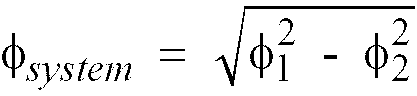
universal joint 10 and Φ2 is the angle of the single Cardanuniversal joint 5. - For an "in-phase" double Cardan universal joint, as shown in FIGS. 1 through 3, where the axes of
pivot 
mechanism 37 can achieve is approximately 15°. - For an "out of phase" double Cardan universal joint 10', as shown in FIG. 6, where the axes of
pivot 
- As an alternative to deliberating miscentering the centering
mechanism 37, the crossring pivot axes ring pivot axes tubular housing 20 with the crossring pivot axes ring pivot axes - For example, in a three joint steering system as shown in FIGS. 4 and 5, if the angle of the single Cardan
universal joint 5 is 17° and the actual angle of a constant velocity double Cardanuniversal joint 10 is 40°, the equivalent angle Φsystem of the three joint system is 17°. If the crossring pivot axes ring pivot axes universal joint 10 is approximately 16.9° and the equivalent angle Φsystem of the three joint system is approximately 1.8°. For an equivalent angle of 1.8°, the system velocity variation is essentially zero, resulting in a nearly constant velocity steering system. - One method of determining the equivalent angle of a double Cardan universal joint 10 having rotated
cross ring axes cross ring axes universal joint 5 in the three joint system shown in FIG. 4 and 5. If the equivalent angle of the rotated axes double Cardan universal joint is within approximately 3° degrees of the single Cardanuniversal joint 5, the velocity variation of the three joint system will be essentially zero.
Claims (13)
- A steering column assembly of the type having a first shaft (4), a second shaft (7), a first universal joint (5) connecting the first shaft (4) to the second shaft (7), the axis of the first shaft (4) being at an angle y to the axis of the second shaft (7), a third shaft (12) and a double cardan universal joint (10) connecting the second shaft (7) to the third shaft (12), the double cardan universal joint comprised of two pivotal second universal joints connected by a connecting yoke, the connecting yoke having a axis extending through the points about which the second universal joints pivot, the axis of the third shaft being at an angle α to the connecting yoke axis, the axis of the second shaft being at an angle β to the connecting yoke axis, characterized in that:
said angle α is not equal to angle β resulting in said double cardan universal joint being of the non-constant type having an equivalent angle Φ, defined by
- The steering column assembly according to claim 1, wherein the connecting yoke has a tubular shape.
- The steering column assembly according to claim 1, wherein each second universal joint includes an annular ring yoke.
- The steering column assembly according to claim 1, wherein the connecting yoke has a tubular shape and each second universal joint includes an annular ring yoke.
- The steering column assembly according to claim 1, wherein the equivalent angle Φ is equal to the angle γ.
- The steering column assembly according to claim 1, wherein the equivalent angle Φ is no greater than the angle γ.
- A steering column assembly of the type having a first shaft (4), a second shaft (7), a first universal joint (5) connecting the first shaft (4) to the second shaft (7), the axis of the first shaft (4) being at an angle γ to the axis of the second shaft (7), a third shaft (12); and a double cardan universal joint connecting the second shaft to the third shaft, the double cardan universal joint comprised of two pivotal second universal joints pivotally connected by a connecting yoke, each second universal joint pivoting about an axis (50a,b) fixed to the connecting yoke (20) and being perpendicular to the longitudinal axis of said yoke (20), said longitudinal axis extending through the points about which the second universal joints pivot, the axis of the third shaft being at an angle α to the connecting yoke axis, the axis of the second shaft being at an angle β to the connecting yoke axis, characterized in that:
said pivot axis (50a) of the second universal joint is perpendicular to the pivot axis (50b) of the other second universal joint resulting in a double cardan universal joint having an equivalent angle Φ, defined by
- The steering column assembly according to claim 7, wherein the connecting yoke has a tubular shape.
- The steering column assembly according to claim 7, wherein each second universal joint includes an annular ring yoke.
- The steering column assembly according to claim 7, wherein the connecting yoke has a tubular shape and each second universal joint includes an annular ring yoke.
- The steering column assembly according to claim 7, wherein the equivalent angle Φ is equal to the angle γ.
- The steering column assembly according to claim 7, wherein the equivalent angle Φ is no greater than angle γ.
- A steering column assembly of the type having a first shaft (4), a second shaft (7), a first universal joint (5) connecting the first shaft (4) to the second shaft (7), the axis of the first shaft (4) being at an angle γ to the axis of the second shaft (7), a third shaft (12), and a double cardan universal joint connecting the second shaft to the third shaft, the double cardan universal joint comprised of two pivotal second universal joints pivotally connected by a connecting yoke, each second universal joint pivoting about an axis (50a,b) fixed to the connecting yoke (20) and being perpendicular to the longitudinal axis of said yoke (20), said longitudinal axis extending through the points about which the second universal joints pivot, the axis of the third shaft being at an angle α to the connecting yoke axis, the axis of the second shaft also being at an angle α to the connecting yoke axis characterized in that:
the pivot axis (50a) of one second universal joint is at an angle λ to the pivot axis (50b) of the other second universal joint, said angle λ being greater than 0° and less than 90°.
Applications Claiming Priority (3)
| Application Number | Priority Date | Filing Date | Title |
|---|---|---|---|
| US08/146,379 US5525110A (en) | 1993-10-29 | 1993-10-29 | Universal joint |
| US146379 | 1993-10-29 | ||
| PCT/US1994/011551 WO1995012073A2 (en) | 1993-10-29 | 1994-10-11 | Universal joint |
Publications (2)
| Publication Number | Publication Date |
|---|---|
| EP0725904A1 EP0725904A1 (en) | 1996-08-14 |
| EP0725904B1 true EP0725904B1 (en) | 1997-12-29 |
Family
ID=22517108
Family Applications (1)
| Application Number | Title | Priority Date | Filing Date |
|---|---|---|---|
| EP94930723A Expired - Lifetime EP0725904B1 (en) | 1993-10-29 | 1994-10-11 | Steering Column Assembly |
Country Status (9)
| Country | Link |
|---|---|
| US (1) | US5525110A (en) |
| EP (1) | EP0725904B1 (en) |
| JP (1) | JPH09511312A (en) |
| CN (1) | CN1048079C (en) |
| AU (1) | AU673962B2 (en) |
| BR (1) | BR9407912A (en) |
| CA (1) | CA2174108A1 (en) |
| DE (1) | DE69407615T2 (en) |
| WO (1) | WO1995012073A2 (en) |
Families Citing this family (30)
| Publication number | Priority date | Publication date | Assignee | Title |
|---|---|---|---|---|
| KR970007582B1 (en) * | 1995-05-23 | 1997-05-10 | 홍성남 | 3D stereo power train |
| US5823881A (en) * | 1995-07-10 | 1998-10-20 | Cornay; Paul Joseph | Universal joint having centering device |
| US5816926A (en) * | 1997-06-03 | 1998-10-06 | The Torrington Company | Ball and socket double cardan motion universal joint |
| BR9907028A (en) | 1998-01-19 | 2000-10-17 | Krupp Presta Aktiengesellschaf | Double joint for steering axles in automobiles |
| US6955608B1 (en) | 1998-01-19 | 2005-10-18 | Krupp Presta Ag | Double joint for steering axles in automobiles |
| JP4289793B2 (en) * | 1998-01-19 | 2009-07-01 | ティッセンクルップ・プレスタ・アクチエンゲゼルシヤフト | Double joint for automobile steering shaft |
| ATE273462T1 (en) | 1998-12-14 | 2004-08-15 | Paul J Cornay | BALL CAM CENTERING DEVICE |
| US6375577B1 (en) * | 1999-10-27 | 2002-04-23 | Abbott Laboratories | Universal style coupling |
| US6383081B1 (en) * | 2000-05-01 | 2002-05-07 | The Torrington Company | Spider for use in a compact universal joint assembly |
| US6758302B2 (en) * | 2001-01-23 | 2004-07-06 | Paccar Inc | Low vibration driveline |
| US6722994B2 (en) * | 2001-03-09 | 2004-04-20 | Deer & Co. | Suspended drive axle and agricultural tractor with same |
| JP2002349593A (en) * | 2001-05-31 | 2002-12-04 | Ntn Corp | Constant velocity universal joint |
| US6623363B2 (en) | 2001-09-27 | 2003-09-23 | The Torrington Company | Universal joint yoke and method of making same |
| US6641324B2 (en) | 2001-10-12 | 2003-11-04 | The Torrington Company | Joint assembly and joint socket sleeve |
| GB2406371B (en) * | 2003-09-23 | 2005-10-19 | Minebea Co Ltd | A steering column universal joint and method of manufacturing the same |
| US20060089202A1 (en) * | 2004-10-25 | 2006-04-27 | Horizon Hobby, Inc. | Constant velocity universal joint system |
| DE102005022474A1 (en) * | 2005-05-14 | 2006-12-14 | Zf Lenksysteme Gmbh | steering shaft |
| ATE538016T1 (en) * | 2005-10-12 | 2012-01-15 | Renault Trucks | VEHICLE WITH A STEERING COLUMN |
| FR2892084B1 (en) * | 2005-10-14 | 2009-06-12 | Peugeot Citroen Automobiles Sa | STEERING COLUMN OF MOTOR VEHICLE |
| US20080126042A1 (en) * | 2006-08-23 | 2008-05-29 | Kim Tyler T | System And Method For Optimum Phasing Of A Three-Shaft Steering Column |
| KR101070635B1 (en) | 2011-05-24 | 2011-10-07 | 한국델파이주식회사 | Constant velocity joint assembly |
| RU2480636C1 (en) * | 2011-11-09 | 2013-04-27 | Открытое акционерное общество "КАМАЗ" | Double universal joint with internal support |
| US8910906B2 (en) * | 2012-05-15 | 2014-12-16 | Hamilton Sundstrand Corporation | Articulable rotational coupling for an aircraft |
| CN103644196A (en) * | 2013-11-26 | 2014-03-19 | 瓦房店轴承砂轮制造有限公司 | Bulb automobile hitch yoke |
| US9644687B2 (en) * | 2015-07-30 | 2017-05-09 | Steering Solutions Ip Holding Corporation | Centering mechanism arrangement for double cardan joints |
| US9670965B2 (en) | 2015-07-30 | 2017-06-06 | Steering Solutions Ip Holding Corporation | Centering mechanism arrangement for double cardan joints |
| US9815497B1 (en) | 2016-05-05 | 2017-11-14 | Toyota Motor Engineering & Manufacturing North America, Inc. | Vehicles including an engine compartment spacer member |
| CN110023063B (en) * | 2016-12-08 | 2021-08-27 | 爱尔康公司 | Apparatus for sealing ophthalmic lens packages |
| KR20230090519A (en) * | 2021-12-15 | 2023-06-22 | 남양넥스모 주식회사 | Intermediate shaft for steering apparatus of vehicle |
| CN116857294A (en) * | 2022-03-28 | 2023-10-10 | 操纵技术Ip控股公司 | Double universal joint constant speed adjustable joint |
Family Cites Families (34)
| Publication number | Priority date | Publication date | Assignee | Title |
|---|---|---|---|---|
| DE664786C (en) * | ||||
| US1911214A (en) * | 1928-08-22 | 1933-05-30 | Manning & Co | Universal joint |
| GB347315A (en) * | 1930-02-01 | 1931-04-30 | Mechanics Universal Joint Comp | Universal joint assembly |
| US1898265A (en) * | 1930-03-12 | 1933-02-21 | Columbia Axle Company | Universal joint |
| FR717790A (en) * | 1930-09-25 | 1932-01-14 | Advanced linkage device for shafts with variable angular position | |
| GB377760A (en) * | 1931-03-09 | 1932-08-04 | Birger Ljungstroem | Improvements in or relating to deflectable power transmission mechanism |
| GB475455A (en) * | 1935-12-21 | 1937-11-19 | Jacques Auguste Parent | Universal transmission joint |
| US2609673A (en) * | 1948-11-27 | 1952-09-09 | Chrysler Corp | Universal joint |
| CH303015A (en) * | 1952-07-30 | 1954-11-15 | Gmbh Gelenkwellenbau | Universal joint. |
| FR1156470A (en) * | 1956-07-20 | 1958-05-16 | Double universal joint coupling | |
| BE566898A (en) * | 1957-07-06 | 1900-01-01 | ||
| US3029618A (en) * | 1958-12-19 | 1962-04-17 | Socite Anonyme Des Roulements | Universal joint of the hooke's type |
| US3028766A (en) * | 1958-12-23 | 1962-04-10 | Louis C Musilli | Flexible universal steering assembly |
| DE1190363B (en) * | 1961-03-06 | 1965-04-01 | J A Kraft Maschinenfabrik | Double joint coupling for connecting the output shaft of the drive with the rotor body of a high-speed stranding machine |
| GB994696A (en) * | 1961-09-22 | 1965-06-10 | Walter Cecil Gower | Improvements in flexible drives |
| US3159013A (en) * | 1961-12-01 | 1964-12-01 | Dana Corp | Double cardan yoke assembly |
| US3165942A (en) * | 1963-02-15 | 1965-01-19 | Frazier F Steiner | Flexible steering column |
| US3319439A (en) * | 1964-05-14 | 1967-05-16 | Daimler Benz Ag | Universal joint |
| FR1486469A (en) * | 1966-05-18 | 1967-06-30 | Renault | Constant velocity joint centering device |
| DE2239488A1 (en) * | 1972-08-11 | 1974-02-21 | Bauer Kompressoren | PISTON MACHINE, IN PARTICULAR DRY RUNNING PISTON COMPRESSORS, WITH GUIDE RING |
| ES456099A1 (en) * | 1976-03-12 | 1978-04-01 | Michel J Luis | Ring and yoke type universal joint |
| JPS54150537A (en) * | 1978-05-17 | 1979-11-26 | Toyota Motor Corp | Double cardan joint |
| US4395246A (en) * | 1980-09-05 | 1983-07-26 | The Bendix Corporation | Universal joint |
| AU562395B2 (en) * | 1981-09-10 | 1987-06-11 | Sony Corporation | Subscription television system |
| FR2515289B1 (en) * | 1981-10-23 | 1986-09-26 | Cardans Cie Financiere | DOUBLE CARDAN AND JOINT JOINT DEVICE |
| FR2526101B1 (en) * | 1982-04-30 | 1987-03-20 | Nacam | |
| JPS6229628A (en) * | 1985-07-29 | 1987-02-07 | Kobe Steel Ltd | Excavation controller for loading shovel |
| FR2605965B1 (en) * | 1986-10-30 | 1991-01-11 | Peugeot | STEERING COLUMN OF PRE-ASSEMBLED VEHICLE |
| JP2611241B2 (en) * | 1987-07-21 | 1997-05-21 | 大同特殊鋼株式会社 | Low alloy nitrocarburized steel |
| SU1581904A1 (en) * | 1988-01-28 | 1990-07-30 | Джамбулский гидромелиоративно-строительный институт | Pivotable coupling |
| AU634731B2 (en) * | 1988-12-02 | 1993-03-04 | Sanden Corporation | Piston ring having a function which is for facilitating supply of lubricating oil into an annular groove of a piston |
| US5094651A (en) * | 1989-06-28 | 1992-03-10 | Cornay Paul J | Universal joint having hemispherical cup-shaped yoke and exterior, lubricating ring |
| DE4207218C2 (en) * | 1992-03-07 | 1996-07-18 | Lemfoerder Metallwaren Ag | Centered double universal joint for steering shafts in motor vehicles |
| US5415588A (en) * | 1993-06-14 | 1995-05-16 | Wier; Francis L. | Wide angle universal joint |
-
1993
- 1993-10-29 US US08/146,379 patent/US5525110A/en not_active Expired - Fee Related
-
1994
- 1994-10-11 AU AU79759/94A patent/AU673962B2/en not_active Expired - Fee Related
- 1994-10-11 DE DE69407615T patent/DE69407615T2/en not_active Expired - Fee Related
- 1994-10-11 EP EP94930723A patent/EP0725904B1/en not_active Expired - Lifetime
- 1994-10-11 CN CN94193961A patent/CN1048079C/en not_active Expired - Fee Related
- 1994-10-11 BR BR9407912A patent/BR9407912A/en not_active IP Right Cessation
- 1994-10-11 WO PCT/US1994/011551 patent/WO1995012073A2/en not_active Ceased
- 1994-10-11 JP JP7512660A patent/JPH09511312A/en not_active Ceased
- 1994-10-11 CA CA002174108A patent/CA2174108A1/en not_active Abandoned
Also Published As
| Publication number | Publication date |
|---|---|
| WO1995012073A3 (en) | 1995-07-20 |
| AU673962B2 (en) | 1996-11-28 |
| DE69407615T2 (en) | 1998-07-16 |
| WO1995012073A2 (en) | 1995-05-04 |
| BR9407912A (en) | 1996-11-26 |
| EP0725904A1 (en) | 1996-08-14 |
| CN1048079C (en) | 2000-01-05 |
| CN1134182A (en) | 1996-10-23 |
| AU7975994A (en) | 1995-05-22 |
| DE69407615D1 (en) | 1998-02-05 |
| CA2174108A1 (en) | 1995-05-04 |
| JPH09511312A (en) | 1997-11-11 |
| US5525110A (en) | 1996-06-11 |
Similar Documents
| Publication | Publication Date | Title |
|---|---|---|
| US5525110A (en) | Universal joint | |
| US3381497A (en) | Universal joint | |
| US5135060A (en) | Articulated coupling for use with a downhole drilling apparatus | |
| US3747368A (en) | Double universal joint | |
| GB2289929A (en) | Assembly of constant velocity ratio universal joint and shaft | |
| US5288273A (en) | Constant velocity universal joint with reduced cage supporting faces | |
| US5816926A (en) | Ball and socket double cardan motion universal joint | |
| EP0155467B1 (en) | Centering device for a constant velocity joint | |
| CA1216436A (en) | Coupling | |
| US5657545A (en) | Fixture for identifying phase angle relationships in a steering shaft assembly | |
| US4516958A (en) | Flexible shaft coupling device | |
| GB2161581A (en) | Drive assembly coupling | |
| GB2086534A (en) | Universal joints | |
| EP1141566B1 (en) | Ball cam centering mechanism | |
| US4036032A (en) | Universal joint | |
| US2984997A (en) | Universal joint | |
| US5415588A (en) | Wide angle universal joint | |
| EP0425220A1 (en) | Universal joint | |
| US4114404A (en) | Universal joint | |
| US4282770A (en) | Steering gear and method of assembling such gear | |
| US20020128077A1 (en) | Constant velocity universal joint | |
| US5733197A (en) | Constant velocity ratio universal joints | |
| US4501571A (en) | Large operating angle constant-speed joint | |
| US20250327488A1 (en) | Constant velocity joint provided with grease retainer | |
| JPS6312047Y2 (en) |
Legal Events
| Date | Code | Title | Description |
|---|---|---|---|
| PUAI | Public reference made under article 153(3) epc to a published international application that has entered the european phase |
Free format text: ORIGINAL CODE: 0009012 |
|
| 17P | Request for examination filed |
Effective date: 19960506 |
|
| AK | Designated contracting states |
Kind code of ref document: A1 Designated state(s): DE FR GB IT PT SE |
|
| GRAG | Despatch of communication of intention to grant |
Free format text: ORIGINAL CODE: EPIDOS AGRA |
|
| 17Q | First examination report despatched |
Effective date: 19961212 |
|
| GRAH | Despatch of communication of intention to grant a patent |
Free format text: ORIGINAL CODE: EPIDOS IGRA |
|
| GRAH | Despatch of communication of intention to grant a patent |
Free format text: ORIGINAL CODE: EPIDOS IGRA |
|
| GRAA | (expected) grant |
Free format text: ORIGINAL CODE: 0009210 |
|
| AK | Designated contracting states |
Kind code of ref document: B1 Designated state(s): DE FR GB IT PT SE |
|
| ITF | It: translation for a ep patent filed | ||
| REF | Corresponds to: |
Ref document number: 69407615 Country of ref document: DE Date of ref document: 19980205 |
|
| ET | Fr: translation filed | ||
| REG | Reference to a national code |
Ref country code: PT Ref legal event code: SC4A Free format text: AVAILABILITY OF NATIONAL TRANSLATION Effective date: 19980217 |
|
| PLBE | No opposition filed within time limit |
Free format text: ORIGINAL CODE: 0009261 |
|
| STAA | Information on the status of an ep patent application or granted ep patent |
Free format text: STATUS: NO OPPOSITION FILED WITHIN TIME LIMIT |
|
| 26N | No opposition filed | ||
| PGFP | Annual fee paid to national office [announced via postgrant information from national office to epo] |
Ref country code: SE Payment date: 20010920 Year of fee payment: 8 Ref country code: FR Payment date: 20010920 Year of fee payment: 8 |
|
| PGFP | Annual fee paid to national office [announced via postgrant information from national office to epo] |
Ref country code: PT Payment date: 20011015 Year of fee payment: 8 |
|
| REG | Reference to a national code |
Ref country code: GB Ref legal event code: IF02 |
|
| PG25 | Lapsed in a contracting state [announced via postgrant information from national office to epo] |
Ref country code: SE Free format text: LAPSE BECAUSE OF NON-PAYMENT OF DUE FEES Effective date: 20021012 |
|
| PG25 | Lapsed in a contracting state [announced via postgrant information from national office to epo] |
Ref country code: PT Free format text: LAPSE BECAUSE OF NON-PAYMENT OF DUE FEES Effective date: 20030430 |
|
| EUG | Se: european patent has lapsed | ||
| PG25 | Lapsed in a contracting state [announced via postgrant information from national office to epo] |
Ref country code: FR Free format text: LAPSE BECAUSE OF NON-PAYMENT OF DUE FEES Effective date: 20030630 |
|
| REG | Reference to a national code |
Ref country code: FR Ref legal event code: ST |
|
| PG25 | Lapsed in a contracting state [announced via postgrant information from national office to epo] |
Ref country code: IT Free format text: LAPSE BECAUSE OF NON-PAYMENT OF DUE FEES Effective date: 20051011 |
|
| PGFP | Annual fee paid to national office [announced via postgrant information from national office to epo] |
Ref country code: GB Payment date: 20051102 Year of fee payment: 12 |
|
| PGFP | Annual fee paid to national office [announced via postgrant information from national office to epo] |
Ref country code: DE Payment date: 20051130 Year of fee payment: 12 |
|
| PG25 | Lapsed in a contracting state [announced via postgrant information from national office to epo] |
Ref country code: DE Free format text: LAPSE BECAUSE OF NON-PAYMENT OF DUE FEES Effective date: 20070501 |
|
| GBPC | Gb: european patent ceased through non-payment of renewal fee |
Effective date: 20061011 |
|
| PG25 | Lapsed in a contracting state [announced via postgrant information from national office to epo] |
Ref country code: GB Free format text: LAPSE BECAUSE OF NON-PAYMENT OF DUE FEES Effective date: 20061011 |