EP0725279A1 - Improved probe wash device - Google Patents
Improved probe wash device Download PDFInfo
- Publication number
- EP0725279A1 EP0725279A1 EP96300648A EP96300648A EP0725279A1 EP 0725279 A1 EP0725279 A1 EP 0725279A1 EP 96300648 A EP96300648 A EP 96300648A EP 96300648 A EP96300648 A EP 96300648A EP 0725279 A1 EP0725279 A1 EP 0725279A1
- Authority
- EP
- European Patent Office
- Prior art keywords
- wash
- probe
- compartment
- diameter
- exhaust
- Prior art date
- Legal status (The legal status is an assumption and is not a legal conclusion. Google has not performed a legal analysis and makes no representation as to the accuracy of the status listed.)
- Withdrawn
Links
- 239000000523 sample Substances 0.000 title claims abstract description 56
- 239000012530 fluid Substances 0.000 claims abstract description 18
- 239000007788 liquid Substances 0.000 claims abstract description 10
- 238000001035 drying Methods 0.000 claims abstract description 5
- 239000003153 chemical reaction reagent Substances 0.000 description 15
- 238000005406 washing Methods 0.000 description 5
- 238000010276 construction Methods 0.000 description 4
- 238000003556 assay Methods 0.000 description 2
- 238000011109 contamination Methods 0.000 description 2
- 239000000427 antigen Substances 0.000 description 1
- 230000000052 comparative effect Effects 0.000 description 1
- 230000007812 deficiency Effects 0.000 description 1
- 238000010790 dilution Methods 0.000 description 1
- 239000012895 dilution Substances 0.000 description 1
- 230000009977 dual effect Effects 0.000 description 1
- 238000010438 heat treatment Methods 0.000 description 1
- 238000005201 scrubbing Methods 0.000 description 1
- XLYOFNOQVPJJNP-UHFFFAOYSA-N water Substances O XLYOFNOQVPJJNP-UHFFFAOYSA-N 0.000 description 1
Images

Classifications
-
- G—PHYSICS
- G01—MEASURING; TESTING
- G01N—INVESTIGATING OR ANALYSING MATERIALS BY DETERMINING THEIR CHEMICAL OR PHYSICAL PROPERTIES
- G01N35/00—Automatic analysis not limited to methods or materials provided for in any single one of groups G01N1/00 - G01N33/00; Handling materials therefor
- G01N35/10—Devices for transferring samples or any liquids to, in, or from, the analysis apparatus, e.g. suction devices, injection devices
- G01N35/1004—Cleaning sample transfer devices
Definitions
- This invention relates to a wash device for a permanent probe, for use in an analyzer, and specifically to improved features that enhance the cleansing provided by the wash device.
- a wash fluid inlet injects wash liquid into a confining compartment into which the probe is inserted, and an exhaust removes it and air, the latter to dry the probe. See, for example, US-A-4,820,497, wherein the wash fluid is supplied from inside the probe. Most commonly, the wash flows as a sheet around the exterior of the probe.
- a device used in an analyzer to wash a probe having an outside diameter having a wash compartment of a predetermined inner diameter, a source of wash fluid that is fluidly connected thereto, and two opposite ends, one of the ends having a probe access opening of a selected entrance diameter, and an exhaust adjacent the other end for removing liquid and air from the wash compartment, characterized in that the compartment includes at a location adjacent to the one end, a constricted passageway of a diameter that is less than the probe access entrance diameter and the predetermined inner diameter, but that is greater than the outside diameter of a probe washed in the device, and a wall surface smoothly connecting the probe access entrance diameter with the constricted passageway diameter so that air is speeded up when flowing into the one end and past the constricted passageway to aid in drying a probe that is being withdrawn from the device.
- a probe wash is provided that more adequately dries the probe to remove all residual liquid.
- Another advantageous feature of the invention is that such a probe wash is more effective in scrubbing the exterior surface of a probe being washed.
- the wash compartment is a generally straight, vertically-oriented cylinder, and wherein the wash fluid inlets and exhaust have each a preferred shape or configuration.
- the wash inlet jets are aimed downwardly.
- the invention is useful regardless of whether the wash compartment is straight, vertically-oriented, or cylindrical, and regardless of the particular shape or orientation of the wash inlets or exhaust.
- an analyzer 10 in which the probe wash device is used preferably comprises sample supply station 12, a cuvette supply station 14, Fig. 2, a reagent supply station 16, Fig. 1, incubator 50, means 20 and 22 for transferring sample and reagent to a cuvette disposed in an outer ring of incubator 50, signal reagent supply station 24, means 26 for transferring signal reagent to the cuvette in an inner ring of incubator 50, cuvette wash station 30, and luminometer 32, all as described in commonly-owned US-A-5,244,633. Any suitable construction can be used for the sample supply station 12, cuvette supply station 14, reagent supply station 16, transfer means 20, 22 and 26, signal reagent supply station 24, wash dispenser 30, and luminometer 32.
- Useful sample transfer devices 13 include those described and claimed in US-A-5,366,697.
- Supply station 16 includes a rotor 34 having an axis of rotation 35.
- Transfer means 20, 22 and 26 are all preferably pivoting aspirators, the aspirator at transfer means 26 having dual probes 36.
- Transfer means 20 preferably uses disposable tips, which can be presented for pick-up on supply station 12. Additional tips 37 can be presented on turntable 38 for use by means 20 during a dilution step.
- the aspirator for transfer means 22 preferably uses a more permanent dispensing tip, which uses a probe wash device 40, described hereinafter in detail.
- Cuvettes are provided for dispensing at station 14 by mounting them, preferably, in the reagent module 100 discussed below, shown in phantom Fig. 1.
- any cuvette can be used, preferably it is a cup-like container "C", having on its inside wall surface 44, an antibody pre-attached to the wall surface, Fig. 2.
- the antibody is useful in a conventional sandwich assay which produces a complex of antibody-antigen labeled antibody for generating a chemiluminescent signal.
- the incubator is preferably that disclosed in said '633 patent, and comprises two rotors which are preferably two concentrically mounted support rings 52, 54 provided with holding apertures (not shown) for receiving and carrying cuvettes C (delivered preferably first to ring 52 by any pusher means 43, Fig. 2), rotating means for independently rotating rings 52 and 54 about a common axis 55, transfer means (not shown) for moving a cuvette, arrow 56 of Fig. 2, from ring 52 to 54, and then off ring 54, processing stations around the rings, and heating means to incubate the contents of the cuvettes on rings 52 and 54.
- Rings 52 and 54 are shown only schematically in Fig. 2 in association with the related components.
- Rotating means for the rings preferably comprise gear teeth 62, 64 disposed on each of rings 52 and 54, respectively, to be driven by pinion gears 66 and 68.
- Figs. 1 and 2 Station 72 is permanently disposed above ring 52 and is the place to which the dispensing tip 37 of aspirator 20, Fig. 1, pivots and descends to dispense sample into a cuvette in ring 52, Fig. 2.
- First reagent addition station 74 is permanently disposed at least above ring 52 so that the permanent tip of aspirator 22 can dispense at least a first reagent into a cuvette in ring 52.
- aspirator 22 can also be used to dispense a second regent, namely a conjugate reagent, as well.
- a further reagent addition station 76 here for signal reagent, is disposed permanently above at least inner ring 54, to descend to dispense signal reagent into a cuvette in ring 54.
- Wash dispensing station 78 is disposed permanently above ring 54 for washing cuvettes using wash dispenser 30.
- Luminometer 32 is permanently disposed above ring 54 for reading chemiluminescence.
- Final removal of the used, finished cuvette from ring 54 can be achieved by any suitable mechanism.
- device 40 comprises a wash compartment which, as shown, comprises a generally straight cylinder 80 vertically disposed within frame 82 and extending between opposite ends 104 and 110.
- End 110 is open to the atmosphere for access by a probe, and has an entrance diameter D 0 , Fig. 3.
- D 1 Fig. 4
- the wash compartment comprises one continuous chamber, with portion 80' described below being part of this continuous chamber since the alignment of the walls of 80' with the walls of 80 is preferably substantially continuous and unbroken.
- Such a construction provides for uniform flow of wash liquid and air.
- a source of wash fluid for example, a pipe or tube 84, Figs. 3-4, is joined to frame 82 at an aperture 86, which aperture fluidly connects via a reduced aperture 88 to an enlarged opening 90 disposed above compartment 80, into which is fixed or formed a member 92 machined or otherwise shaped to have a continuation 80' of compartment 80, that is, an axial bore of the same diameter D 1 that aligns with compartment 80, Fig. 4; an annular groove 94 aligned to fluidly connect with aperture 88; and jet apertures 96 feeding into compartment 80' at a first location, the jets being described in more detail hereinafter.
- an exhaust opening 102 extends from the compartment.
- An exhaust such as a conventional vacuum source (not shown) is connected to opening 102 via pipe or tubing 103.
- location 100 is disposed slightly above bottom surface 104 of compartment 80, leaving a soak volume for wash fluid to collect and wash, an inserted probe.
- probe wash device 40 is improved in several respects, Fig. 4.
- opening 110 of member 92 is provided with a constricted passageway 112 inside and below opening 110, and adjacent to and just above, jets 96. That is, inside diameter D 2 of opening 110 is slightly less than D 1 , and terminates in an abrupt shoulder 114.
- Such a constricted passageway preferably encircles the entire circumference of the wash compartment 80'.
- D 2 can be 2.9 mm if D 1 is 3.5 mm, which is still large enough, however, Fig. 5, to receive a probe P during washing, spaced from the wall of opening 110.
- the relationship of diameter D 2 to D 1 or D 0 is not critical, except that D 0 must be larger that D 2 .
- wall surface 118 that connects passageway 112 to upper end 110 is a continuous surface that smoothly connects end 110 and the shoulder 114. Such a surface, lacking interior or exterior corners, causes air to flow in end 110 and past shoulder 114 at greatly increased velocities.
- wall surface 118 is shown to be gradually curved and with a convex cross-sectional shape, other smooth transit surfaces can be used, for example, a cone surface 118A, Fig. 6, connecting end 110A and passageway 112A. What is not acceptable is either of the constructions shown in Figs. 7A and 7B. These do not appreciably increase the air flow velocity.
- the diameter D 1 is larger that diameter D 2 , and especially at the location of jets 96.
- the reason is that the sudden increase in diameter D 1 causes a pressure drop that allows the jetted wash liquid to strike any probe present, unlike what would occur without the pressure drop.
- a further improvement of device 40 includes the construction of jets 96. These are provided as a plurality of separate apertures, as shown, Fig. 3, all radiating inward from groove 94 to compartment 80'. Such separate apertures cause the wash fluid to be delivered as separate jets. It is believed this entrains air in the wash water as the fluid flows into compartment 80' and 80. This entrained air is thought to help scour the exterior of a probe being washed, arrow 120, Fig. 5.
- jets 96 are aimed generally downward, that is, toward exhaust location 100 rather than perpendicularly out into compartment 80'. This in turn aids in forcing wash fluid to flow downwardly, arrow 120.
- a probe P When in use, Fig. 5, a probe P is inserted as shown, with its end 130 being spaced from surface 104. Wash fluid is injected via jets 96 and washes downwardly, arrow 120, the probe exterior surface. The exhaust at location 100 is effective to remove the spent wash fluid during and after this action. Optionally, at the same time a wash fluid can be injected internally, and downwardly, probe P (not shown) to be removed also out the exhaust.
- the exhaust aperture 102 continues to exhaust the contents of compartment 80, thus forcing in drying air at opening 110, arrows 128. Because of the constricted passageway 112, the air flow is speeded up at this location, providing a more effective removal of residual liquid as probe P is raised vertically, arrow 131.
Landscapes
- Physics & Mathematics (AREA)
- Health & Medical Sciences (AREA)
- Life Sciences & Earth Sciences (AREA)
- Chemical & Material Sciences (AREA)
- Analytical Chemistry (AREA)
- Biochemistry (AREA)
- General Health & Medical Sciences (AREA)
- General Physics & Mathematics (AREA)
- Immunology (AREA)
- Pathology (AREA)
- Automatic Analysis And Handling Materials Therefor (AREA)
Abstract
A probe wash device (40) for an analyzer (10) comprises a wash compartment (80) and a source of wash fluid (84) and an exhaust for wash fluid (103) both fluidly connected to the compartment. Adjacent to the location of the connection of the source of wash fluid to the compartment, a constricted passageway (112) is provided to force in-drawn air to speed up during drying, thus ensuring complete removal of residual liquid.
Description
- This invention relates to a wash device for a permanent probe, for use in an analyzer, and specifically to improved features that enhance the cleansing provided by the wash device.
- It is common practice in analyzers using a wet assay, to transfer at least some of the utilized liquids, for example, the reagents, via a permanent aspirating probe. To avoid contamination, at least some of such permanent probes are washed between uses, in a probe wash device on the analyzer. A wash fluid inlet injects wash liquid into a confining compartment into which the probe is inserted, and an exhaust removes it and air, the latter to dry the probe. See, for example, US-A-4,820,497, wherein the wash fluid is supplied from inside the probe. Most commonly, the wash flows as a sheet around the exterior of the probe.
- Several problems exist in prior art probe washes. For one thing, we have discovered that they do not always completely dry the probe after washing, leaving residual drops of liquid on the probe surface. That is, merely sucking some air to flow past the probe while confined in the wash compartment, may provide inadequate drying. These residuals can cause contamination to the extent they contain other reagents, and so forth. Also, the wash flow, if not entrained with air, may not completely or adequately wash off the surface of the probe.
- Thus, there has been a need, prior to this invention, to improve upon probe wash devices to overcome these deficiencies.
- We have designed a probe wash device that solves the noted problems.
- More specifically, there is provided a device used in an analyzer to wash a probe having an outside diameter, the device having a wash compartment of a predetermined inner diameter, a source of wash fluid that is fluidly connected thereto, and two opposite ends, one of the ends having a probe access opening of a selected entrance diameter, and an exhaust adjacent the other end for removing liquid and air from the wash compartment, characterized in that the compartment includes at a location adjacent to the one end, a constricted passageway of a diameter that is less than the probe access entrance diameter and the predetermined inner diameter, but that is greater than the outside diameter of a probe washed in the device, and a wall surface smoothly connecting the probe access entrance diameter with the constricted passageway diameter so that air is speeded up when flowing into the one end and past the constricted passageway to aid in drying a probe that is being withdrawn from the device.
- Accordingly, it is an advantageous feature of the invention that a probe wash is provided that more adequately dries the probe to remove all residual liquid.
- Another advantageous feature of the invention is that such a probe wash is more effective in scrubbing the exterior surface of a probe being washed.
- Other advantageous features will become apparent upon reference to the following "Detailed Description", when read in light of the attached drawings.
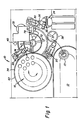
- Fig. 1 is a partially schematic, fragmentary plan view of an analyzer utilizing the probe wash device of the invention;
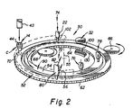
- Fig. 2 is a partially schematic, isometric view illustrating the functioning of the incubator of the analyzer;
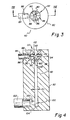
- Fig. 3 is an enlarged plan view of just the probe wash device of the invention;
- Fig. 4 is an elevational sectional view taken generally along the line IV-IV of Fig. 3;
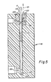
- Fig. 5 is a section view similar to that of Fig. 4 but with a probe in place for washing;
- Fig. 6 is a fragmentary section view similar to that of Fig. 4, but showing an alternate embodiment; and
- Figs. 7A and 7B are fragmentary section views similar to that of Fig. 6, but of unacceptable comparative examples.
- The invention is hereinafter described in connection with the preferred embodiment, in which the wash compartment is a generally straight, vertically-oriented cylinder, and wherein the wash fluid inlets and exhaust have each a preferred shape or configuration. For example, the wash inlet jets are aimed downwardly. In addition, the invention is useful regardless of whether the wash compartment is straight, vertically-oriented, or cylindrical, and regardless of the particular shape or orientation of the wash inlets or exhaust.
- Descriptions such as "above", "below", "downward", "vertical", and the like refer to orientations of parts of the invention during their intended use.
- As shown in Fig. 1, an analyzer 10 in which the probe wash device is used, preferably comprises
sample supply station 12, acuvette supply station 14, Fig. 2, areagent supply station 16, Fig. 1,incubator 50, means 20 and 22 for transferring sample and reagent to a cuvette disposed in an outer ring ofincubator 50, signalreagent supply station 24, means 26 for transferring signal reagent to the cuvette in an inner ring ofincubator 50,cuvette wash station 30, andluminometer 32, all as described in commonly-owned US-A-5,244,633. Any suitable construction can be used for thesample supply station 12,cuvette supply station 14,reagent supply station 16, transfer means 20, 22 and 26, signalreagent supply station 24,wash dispenser 30, andluminometer 32. Usefulsample transfer devices 13 include those described and claimed in US-A-5,366,697.Supply station 16 includes arotor 34 having an axis of rotation 35. Transfer means 20, 22 and 26 are all preferably pivoting aspirators, the aspirator at transfer means 26 havingdual probes 36. Transfer means 20 preferably uses disposable tips, which can be presented for pick-up onsupply station 12. Additional tips 37 can be presented onturntable 38 for use bymeans 20 during a dilution step. On the other hand, the aspirator for transfer means 22 preferably uses a more permanent dispensing tip, which uses aprobe wash device 40, described hereinafter in detail. - Cuvettes are provided for dispensing at
station 14 by mounting them, preferably, in thereagent module 100 discussed below, shown in phantom Fig. 1. - Although any cuvette can be used, preferably it is a cup-like container "C", having on its inside wall surface 44, an antibody pre-attached to the wall surface, Fig. 2. The antibody is useful in a conventional sandwich assay which produces a complex of antibody-antigen labeled antibody for generating a chemiluminescent signal.
- The incubator is preferably that disclosed in said '633 patent, and comprises two rotors which are preferably two concentrically mounted
support rings ring 52 by any pusher means 43, Fig. 2), rotating means for independently rotatingrings common axis 55, transfer means (not shown) for moving a cuvette,arrow 56 of Fig. 2, fromring 52 to 54, and then offring 54, processing stations around the rings, and heating means to incubate the contents of the cuvettes onrings Rings gear teeth rings pinion gears - As noted above, various processing stations are disposed around the circumference of
rings entrance port 70 for cuvettes C. They are as follows, Figs. 1 and 2:Station 72 is permanently disposed abovering 52 and is the place to which the dispensing tip 37 ofaspirator 20, Fig. 1, pivots and descends to dispense sample into a cuvette inring 52, Fig. 2. Firstreagent addition station 74 is permanently disposed at least abovering 52 so that the permanent tip ofaspirator 22 can dispense at least a first reagent into a cuvette inring 52. Optionally,aspirator 22 can also be used to dispense a second regent, namely a conjugate reagent, as well. A furtherreagent addition station 76, here for signal reagent, is disposed permanently above at leastinner ring 54, to descend to dispense signal reagent into a cuvette inring 54.Wash dispensing station 78 is disposed permanently abovering 54 for washing cuvettes usingwash dispenser 30.Luminometer 32 is permanently disposed abovering 54 for reading chemiluminescence. - Final removal of the used, finished cuvette from
ring 54 can be achieved by any suitable mechanism. - With respect to the
probe wash device 40 in particular, first, as is conventional, Figs. 3-4,device 40 comprises a wash compartment which, as shown, comprises a generallystraight cylinder 80 vertically disposed withinframe 82 and extending betweenopposite ends End 110 is open to the atmosphere for access by a probe, and has an entrance diameter D0, Fig. 3. For most of its length, it has a predetermined inside diameter D1, Fig. 4, which can be, for example, 3.5 mm, depending on the outside diameter of probe P, Fig. 5. Most preferably, the wash compartment comprises one continuous chamber, with portion 80' described below being part of this continuous chamber since the alignment of the walls of 80' with the walls of 80 is preferably substantially continuous and unbroken. Such a construction provides for uniform flow of wash liquid and air. - A source of wash fluid, for example, a pipe or
tube 84, Figs. 3-4, is joined toframe 82 at anaperture 86, which aperture fluidly connects via a reducedaperture 88 to an enlargedopening 90 disposed abovecompartment 80, into which is fixed or formed amember 92 machined or otherwise shaped to have a continuation 80' ofcompartment 80, that is, an axial bore of the same diameter D1 that aligns withcompartment 80, Fig. 4; anannular groove 94 aligned to fluidly connect withaperture 88; andjet apertures 96 feeding into compartment 80' at a first location, the jets being described in more detail hereinafter. - At a
location 100 adjacent but spaced fromend 104, and below the location ofjets 96, anexhaust opening 102 extends from the compartment. An exhaust such as a conventional vacuum source (not shown) is connected to opening 102 via pipe ortubing 103. Most preferably,location 100 is disposed slightly abovebottom surface 104 ofcompartment 80, leaving a soak volume for wash fluid to collect and wash, an inserted probe. - In accordance with the invention,
probe wash device 40 is improved in several respects, Fig. 4. In one, opening 110 ofmember 92 is provided with aconstricted passageway 112 inside and below opening 110, and adjacent to and just above,jets 96. That is, inside diameter D2 ofopening 110 is slightly less than D1, and terminates in anabrupt shoulder 114. Such a constricted passageway preferably encircles the entire circumference of the wash compartment 80'. For example, D2 can be 2.9 mm if D1 is 3.5 mm, which is still large enough, however, Fig. 5, to receive a probe P during washing, spaced from the wall of opening 110. The relationship of diameter D2 to D1 or D0 is not critical, except that D0 must be larger that D2. - Importantly,
wall surface 118 that connectspassageway 112 toupper end 110 is a continuous surface that smoothly connectsend 110 and theshoulder 114. Such a surface, lacking interior or exterior corners, causes air to flow inend 110 andpast shoulder 114 at greatly increased velocities. Althoughwall surface 118 is shown to be gradually curved and with a convex cross-sectional shape, other smooth transit surfaces can be used, for example, acone surface 118A, Fig. 6, connecting end 110A andpassageway 112A. What is not acceptable is either of the constructions shown in Figs. 7A and 7B. These do not appreciably increase the air flow velocity. - Below
shoulder 114, Fig. 4, for example, at portion 80', the diameter D1 is larger that diameter D2, and especially at the location ofjets 96. The reason is that the sudden increase in diameter D1 causes a pressure drop that allows the jetted wash liquid to strike any probe present, unlike what would occur without the pressure drop. - A further improvement of
device 40 includes the construction ofjets 96. These are provided as a plurality of separate apertures, as shown, Fig. 3, all radiating inward fromgroove 94 to compartment 80'. Such separate apertures cause the wash fluid to be delivered as separate jets. It is believed this entrains air in the wash water as the fluid flows intocompartment 80' and 80. This entrained air is thought to help scour the exterior of a probe being washed,arrow 120, Fig. 5. - Still further,
jets 96 are aimed generally downward, that is, towardexhaust location 100 rather than perpendicularly out into compartment 80'. This in turn aids in forcing wash fluid to flow downwardly,arrow 120. - When in use, Fig. 5, a probe P is inserted as shown, with its
end 130 being spaced fromsurface 104. Wash fluid is injected viajets 96 and washes downwardly,arrow 120, the probe exterior surface. The exhaust atlocation 100 is effective to remove the spent wash fluid during and after this action. Optionally, at the same time a wash fluid can be injected internally, and downwardly, probe P (not shown) to be removed also out the exhaust. - Following the actual washing, the
exhaust aperture 102 continues to exhaust the contents ofcompartment 80, thus forcing in drying air atopening 110,arrows 128. Because of the constrictedpassageway 112, the air flow is speeded up at this location, providing a more effective removal of residual liquid as probe P is raised vertically,arrow 131. - The invention disclosed herein may be practiced in the absence of any element which is not specifically disclosed herein.
Claims (5)
- A device used in an analyzer to wash a probe having an outside diameter, the device having a wash compartment of a predetermined inner diameter, a source of wash fluid that is fluidly connected thereto, and two opposite ends, one of the ends having a probe access opening of a selected entrance diameter, and an exhaust adjacent the other end for removing liquid and air from the wash compartment,
characterized in that the compartment includes at a location adjacent to the one end, a constricted passageway of a diameter that is less than the probe access entrance diameter and the predetermined inner diameter, but that is greater than the outside diameter of a probe washed in the device, and a wall surface smoothly connecting the probe access entrance diameter with the constricted passageway diameter so that air is speeded up when flowing into the one end and past the constricted passageway to aid in drying a probe that is being withdrawn from the device. - A device as defined in claim 1, wherein the source of wash fluid is connected via a plurality of separate apertures opening into the compartment, at a portion of the compartment having the predetermined inner diameter.
- A device as defined in claim 2, wherein the apertures are aimed toward the other end and the exhaust, so that wash fluid is encouraged to flow toward the exhaust.
- A device as defined in any one of claims 1 to 3, wherein the wall surface is gradually curved.
- A device as defined in any one of claims 1 to 4, wherein the wash compartment extends generally vertically.
Applications Claiming Priority (2)
| Application Number | Priority Date | Filing Date | Title |
|---|---|---|---|
| US38105195A | 1995-01-31 | 1995-01-31 | |
| US381051 | 1995-01-31 |
Publications (1)
| Publication Number | Publication Date |
|---|---|
| EP0725279A1 true EP0725279A1 (en) | 1996-08-07 |
Family
ID=23503459
Family Applications (1)
| Application Number | Title | Priority Date | Filing Date |
|---|---|---|---|
| EP96300648A Withdrawn EP0725279A1 (en) | 1995-01-31 | 1996-01-30 | Improved probe wash device |
Country Status (4)
| Country | Link |
|---|---|
| EP (1) | EP0725279A1 (en) |
| JP (1) | JPH08248035A (en) |
| AU (1) | AU693974B2 (en) |
| CA (1) | CA2167471A1 (en) |
Cited By (19)
| Publication number | Priority date | Publication date | Assignee | Title |
|---|---|---|---|---|
| WO1997035173A3 (en) * | 1996-03-18 | 1997-12-04 | Device for cleaning pipette needles or stirrers | |
| US6575181B1 (en) * | 1999-10-25 | 2003-06-10 | Merck & Co., Inc. | Probe wash vessel having removable inner cannula |
| EP1118861A3 (en) * | 2000-01-19 | 2004-01-14 | Mettler-Toledo GmbH | Washing apparatus for analytical device and corresponding driving means |
| WO2006007245A1 (en) * | 2004-06-17 | 2006-01-19 | Abbott Laboratories | Probe washing cups and methods |
| EP2025418A1 (en) * | 2007-08-09 | 2009-02-18 | Hitachi High-Technologies Corporation | Automatic analyzer with pipette cleaning |
| WO2011053756A1 (en) * | 2009-10-30 | 2011-05-05 | Douglas Machine Inc. | Apparatus and methods for cleaning reagent dispensing tips of a screening unit |
| EP2076323A4 (en) * | 2006-10-27 | 2012-05-02 | Siemens Healthcare Diagnostics | METHOD AND DEVICE FOR CLEANING ASPIRATION PROBE AND DISTRIBUTING LIQUID |
| CN102630190A (en) * | 2009-11-20 | 2012-08-08 | 西门子医疗保健诊断公司 | Apparatus, systems, and methods adapted to rinse and dry clinical analyzer sample probes |
| EP2205365A4 (en) * | 2007-10-17 | 2014-02-19 | Aushon Biosystems | Continual flow pin washer |
| CN104024868A (en) * | 2011-12-26 | 2014-09-03 | 株式会社日立高新技术 | Automatic analysis device |
| CN105327891A (en) * | 2015-12-14 | 2016-02-17 | 重庆南方数控设备有限责任公司 | Needle washing device |
| CN105436134A (en) * | 2015-12-14 | 2016-03-30 | 重庆南方数控设备有限责任公司 | Needle washing device for blood rheometer |
| JPWO2015111470A1 (en) * | 2014-01-27 | 2017-03-23 | 株式会社日立ハイテクノロジーズ | Automatic analyzer |
| GB2550548A (en) * | 2016-05-09 | 2017-11-29 | Markes International Ltd | A sampling apparatus |
| CN109475907A (en) * | 2016-07-21 | 2019-03-15 | 西门子医疗保健诊断公司 | Basin and High Velocity Air Solutions |
| CN110023483A (en) * | 2016-10-13 | 2019-07-16 | 昕芙旎雅有限公司 | Culture vessel links device, culture systems and the method for washing needle |
| CN112916522A (en) * | 2021-04-14 | 2021-06-08 | 安图实验仪器(郑州)有限公司 | Sample adding needle cleaning station and sample adding needle cleaning system for biochemical immunity instrument |
| US11499896B2 (en) | 2016-05-09 | 2022-11-15 | Markes International Limited | Sampling apparatus with a sorbent in a recess |
| US12528086B2 (en) | 2020-05-01 | 2026-01-20 | Agilent Technologies, Inc. | Pipette tip washing devices and methods |
Families Citing this family (5)
| Publication number | Priority date | Publication date | Assignee | Title |
|---|---|---|---|---|
| JP5449967B2 (en) * | 2009-10-05 | 2014-03-19 | 日立アロカメディカル株式会社 | Nozzle cleaning unit |
| CN103521480B (en) * | 2012-07-06 | 2016-10-26 | 深圳市麦迪聪医疗电子有限公司 | A kind of cleaning method of the automatic clearing apparatus of sampling needle |
| CN105327907A (en) * | 2015-12-14 | 2016-02-17 | 重庆南方数控设备有限责任公司 | Vortex type needle washing device for cleaning sampling needles |
| CN105537180A (en) * | 2015-12-14 | 2016-05-04 | 重庆南方数控设备有限责任公司 | Vortex type sampling needle washing device |
| CN114072680B (en) * | 2019-07-10 | 2025-05-06 | 株式会社日立高新技术 | Automatic analysis device and method for operating the automatic analysis device |
Citations (4)
| Publication number | Priority date | Publication date | Assignee | Title |
|---|---|---|---|---|
| US4495149A (en) * | 1981-09-18 | 1985-01-22 | Toa Medical Electronic Co., Ltd. | Optical-type automatic analyzing and measuring apparatus |
| US4820497A (en) * | 1986-06-23 | 1989-04-11 | E. I. Du Pont De Nemours And Company | Movable cleaning assembly for an aspirating needle |
| EP0472213A2 (en) * | 1990-08-24 | 1992-02-26 | Olympus Optical Co., Ltd. | Probe washing vessel |
| EP0602802A1 (en) * | 1992-12-17 | 1994-06-22 | Beckman Instruments, Inc. | Fluid probe washing apparatus and method |
Family Cites Families (1)
| Publication number | Priority date | Publication date | Assignee | Title |
|---|---|---|---|---|
| FR2606885B1 (en) * | 1986-11-14 | 1989-08-04 | Abx Sarl | DEVICE FOR CLEANING A LIQUID COLLECTION NEEDLE |
-
1996
- 1996-01-17 CA CA 2167471 patent/CA2167471A1/en not_active Abandoned
- 1996-01-24 JP JP994396A patent/JPH08248035A/en active Pending
- 1996-01-30 AU AU42252/96A patent/AU693974B2/en not_active Ceased
- 1996-01-30 EP EP96300648A patent/EP0725279A1/en not_active Withdrawn
Patent Citations (4)
| Publication number | Priority date | Publication date | Assignee | Title |
|---|---|---|---|---|
| US4495149A (en) * | 1981-09-18 | 1985-01-22 | Toa Medical Electronic Co., Ltd. | Optical-type automatic analyzing and measuring apparatus |
| US4820497A (en) * | 1986-06-23 | 1989-04-11 | E. I. Du Pont De Nemours And Company | Movable cleaning assembly for an aspirating needle |
| EP0472213A2 (en) * | 1990-08-24 | 1992-02-26 | Olympus Optical Co., Ltd. | Probe washing vessel |
| EP0602802A1 (en) * | 1992-12-17 | 1994-06-22 | Beckman Instruments, Inc. | Fluid probe washing apparatus and method |
Cited By (31)
| Publication number | Priority date | Publication date | Assignee | Title |
|---|---|---|---|---|
| EP1213588A1 (en) * | 1996-03-18 | 2002-06-12 | Roche Diagnostics GmbH | Device for cleaning pipette needles or stirrers |
| US7300525B2 (en) * | 1996-03-18 | 2007-11-27 | Roche Diagnostics Gmbh | Device for cleaning pipette probes or stirrers |
| WO1997035173A3 (en) * | 1996-03-18 | 1997-12-04 | Device for cleaning pipette needles or stirrers | |
| US6575181B1 (en) * | 1999-10-25 | 2003-06-10 | Merck & Co., Inc. | Probe wash vessel having removable inner cannula |
| EP1118861A3 (en) * | 2000-01-19 | 2004-01-14 | Mettler-Toledo GmbH | Washing apparatus for analytical device and corresponding driving means |
| WO2006007245A1 (en) * | 2004-06-17 | 2006-01-19 | Abbott Laboratories | Probe washing cups and methods |
| US7621282B2 (en) | 2004-06-17 | 2009-11-24 | Abbott Laboratories, Inc. | Probe washing cups and methods |
| US8171946B2 (en) | 2004-06-17 | 2012-05-08 | Abbott Laboratories | Probe washing cups and methods |
| EP2076323A4 (en) * | 2006-10-27 | 2012-05-02 | Siemens Healthcare Diagnostics | METHOD AND DEVICE FOR CLEANING ASPIRATION PROBE AND DISTRIBUTING LIQUID |
| EP2025418A1 (en) * | 2007-08-09 | 2009-02-18 | Hitachi High-Technologies Corporation | Automatic analyzer with pipette cleaning |
| EP2205365A4 (en) * | 2007-10-17 | 2014-02-19 | Aushon Biosystems | Continual flow pin washer |
| EP3175931A1 (en) * | 2007-10-17 | 2017-06-07 | Aushon Biosystems | Continual flow pin washer |
| WO2011053756A1 (en) * | 2009-10-30 | 2011-05-05 | Douglas Machine Inc. | Apparatus and methods for cleaning reagent dispensing tips of a screening unit |
| US20120211026A1 (en) * | 2009-10-30 | 2012-08-23 | Richard Jerome Schoeneck | Apparatus and Methods for Cleaning Reagent Dispensing Tips of a Screening Unit |
| CN102630190A (en) * | 2009-11-20 | 2012-08-08 | 西门子医疗保健诊断公司 | Apparatus, systems, and methods adapted to rinse and dry clinical analyzer sample probes |
| US9063107B2 (en) | 2009-11-20 | 2015-06-23 | Siemens Healthcare Diagnostics Inc. | Apparatus, systems, and methods adapted to rinse and dry clinical analyzer sample probes |
| CN102630190B (en) * | 2009-11-20 | 2015-11-25 | 西门子医疗保健诊断公司 | Be suitable for equipment, the system and method for flushing and dry clinical analysers sample probe |
| CN104024868A (en) * | 2011-12-26 | 2014-09-03 | 株式会社日立高新技术 | Automatic analysis device |
| JPWO2015111470A1 (en) * | 2014-01-27 | 2017-03-23 | 株式会社日立ハイテクノロジーズ | Automatic analyzer |
| CN105436134A (en) * | 2015-12-14 | 2016-03-30 | 重庆南方数控设备有限责任公司 | Needle washing device for blood rheometer |
| CN105327891A (en) * | 2015-12-14 | 2016-02-17 | 重庆南方数控设备有限责任公司 | Needle washing device |
| US11499896B2 (en) | 2016-05-09 | 2022-11-15 | Markes International Limited | Sampling apparatus with a sorbent in a recess |
| GB2550548A (en) * | 2016-05-09 | 2017-11-29 | Markes International Ltd | A sampling apparatus |
| CN109475907A (en) * | 2016-07-21 | 2019-03-15 | 西门子医疗保健诊断公司 | Basin and High Velocity Air Solutions |
| EP3487640A4 (en) * | 2016-07-21 | 2019-07-10 | Siemens Healthcare Diagnostics Inc. | BAC AND HIGH SPEED AIR SOLUTION |
| US20190275570A1 (en) * | 2016-07-21 | 2019-09-12 | Siemens Healthcare Diagnostics Inc. | Basin and high speed air solution |
| US11517948B2 (en) | 2016-07-21 | 2022-12-06 | Siemens Healthcare Diagnostics Inc. | Basin and high speed air solution |
| CN110023483A (en) * | 2016-10-13 | 2019-07-16 | 昕芙旎雅有限公司 | Culture vessel links device, culture systems and the method for washing needle |
| US12528086B2 (en) | 2020-05-01 | 2026-01-20 | Agilent Technologies, Inc. | Pipette tip washing devices and methods |
| CN112916522A (en) * | 2021-04-14 | 2021-06-08 | 安图实验仪器(郑州)有限公司 | Sample adding needle cleaning station and sample adding needle cleaning system for biochemical immunity instrument |
| CN112916522B (en) * | 2021-04-14 | 2025-04-29 | 安图实验仪器(郑州)有限公司 | Sample needle cleaning station and sample needle cleaning system for biochemical immunoassay |
Also Published As
| Publication number | Publication date |
|---|---|
| JPH08248035A (en) | 1996-09-27 |
| CA2167471A1 (en) | 1996-08-01 |
| AU4225296A (en) | 1996-08-08 |
| AU693974B2 (en) | 1998-07-09 |
Similar Documents
| Publication | Publication Date | Title |
|---|---|---|
| CA2167471A1 (en) | Probe wash device | |
| US4730631A (en) | Probe wash station | |
| JP2943309B2 (en) | Nozzle device | |
| US5827744A (en) | Method and apparatus for cleaning a liquid dispensing probe | |
| JP4406643B2 (en) | Liquid sampling probe and cleaning fluidics system | |
| EP1766418B1 (en) | Probe washing cups and methods | |
| JP2007271427A (en) | Pipette tip | |
| WO1997046319A1 (en) | High-speed liquid deposition device for biological molecule array formation | |
| JP2013134142A (en) | Automatic analyzer | |
| JP2000506979A (en) | Pipette probe or stirrer cleaning device | |
| CA2239974A1 (en) | Apparatus and method for washing a pipette probe | |
| WO1991016978A1 (en) | Manifold liquid handling device with backsip function | |
| JP4175916B2 (en) | Automatic analyzer | |
| JPH1090280A (en) | Liquid dispenser and distributing device | |
| US5185269A (en) | Immunobead aspirator and method of use | |
| JPH08285861A (en) | Nozzle cleaner | |
| CN112108461A (en) | Probe cleaning device and method | |
| JP3720461B2 (en) | Transfer device | |
| JP3276551B2 (en) | Sample stirring / suction device | |
| JP3717859B2 (en) | Chemical analyzer | |
| JPH11271331A (en) | Washing mechanism of sampling nozzle | |
| JPH11304821A (en) | Cleaning equipment | |
| WO1997011375A1 (en) | Means and method for washing reaction vessels | |
| WO1999004271A1 (en) | Nozzle washing device | |
| CN114720455A (en) | Reaction vessel and sample analyzer |
Legal Events
| Date | Code | Title | Description |
|---|---|---|---|
| PUAI | Public reference made under article 153(3) epc to a published international application that has entered the european phase |
Free format text: ORIGINAL CODE: 0009012 |
|
| AK | Designated contracting states |
Kind code of ref document: A1 Designated state(s): AT BE CH DE DK FR GB GR IT LI MC NL SE |
|
| AX | Request for extension of the european patent |
Free format text: SI PAYMENT 960207 |
|
| RAX | Requested extension states of the european patent have changed |
Free format text: SI PAYMENT 960207 |
|
| STAA | Information on the status of an ep patent application or granted ep patent |
Free format text: STATUS: THE APPLICATION IS DEEMED TO BE WITHDRAWN |
|
| 18D | Application deemed to be withdrawn |
Effective date: 19970208 |