EP0724696B1 - Force applying devices - Google Patents
Force applying devices Download PDFInfo
- Publication number
- EP0724696B1 EP0724696B1 EP94928972A EP94928972A EP0724696B1 EP 0724696 B1 EP0724696 B1 EP 0724696B1 EP 94928972 A EP94928972 A EP 94928972A EP 94928972 A EP94928972 A EP 94928972A EP 0724696 B1 EP0724696 B1 EP 0724696B1
- Authority
- EP
- European Patent Office
- Prior art keywords
- load
- spring
- force
- housing
- movement
- Prior art date
- Legal status (The legal status is an assumption and is not a legal conclusion. Google has not performed a legal analysis and makes no representation as to the accuracy of the status listed.)
- Expired - Lifetime
Links
Images
Classifications
-
- B—PERFORMING OPERATIONS; TRANSPORTING
- B60—VEHICLES IN GENERAL
- B60G—VEHICLE SUSPENSION ARRANGEMENTS
- B60G11/00—Resilient suspensions characterised by arrangement, location or kind of springs
- B60G11/14—Resilient suspensions characterised by arrangement, location or kind of springs having helical, spiral or coil springs only
- B60G11/15—Coil springs resisting deflection by winding up
-
- F—MECHANICAL ENGINEERING; LIGHTING; HEATING; WEAPONS; BLASTING
- F16—ENGINEERING ELEMENTS AND UNITS; GENERAL MEASURES FOR PRODUCING AND MAINTAINING EFFECTIVE FUNCTIONING OF MACHINES OR INSTALLATIONS; THERMAL INSULATION IN GENERAL
- F16F—SPRINGS; SHOCK-ABSORBERS; MEANS FOR DAMPING VIBRATION
- F16F1/00—Springs
- F16F1/02—Springs made of steel or other material having low internal friction; Wound, torsion, leaf, cup, ring or the like springs, the material of the spring not being relevant
- F16F1/04—Wound springs
- F16F1/12—Attachments or mountings
- F16F1/127—Attachments or mountings allowing rotation about axis of spring
-
- F—MECHANICAL ENGINEERING; LIGHTING; HEATING; WEAPONS; BLASTING
- F16—ENGINEERING ELEMENTS AND UNITS; GENERAL MEASURES FOR PRODUCING AND MAINTAINING EFFECTIVE FUNCTIONING OF MACHINES OR INSTALLATIONS; THERMAL INSULATION IN GENERAL
- F16L—PIPES; JOINTS OR FITTINGS FOR PIPES; SUPPORTS FOR PIPES, CABLES OR PROTECTIVE TUBING; MEANS FOR THERMAL INSULATION IN GENERAL
- F16L3/00—Supports for pipes, cables or protective tubing, e.g. hangers, holders, clamps, cleats, clips, brackets
- F16L3/16—Supports for pipes, cables or protective tubing, e.g. hangers, holders, clamps, cleats, clips, brackets with special provision allowing movement of the pipe
- F16L3/20—Supports for pipes, cables or protective tubing, e.g. hangers, holders, clamps, cleats, clips, brackets with special provision allowing movement of the pipe allowing movement in transverse direction
- F16L3/205—Supports for pipes, cables or protective tubing, e.g. hangers, holders, clamps, cleats, clips, brackets with special provision allowing movement of the pipe allowing movement in transverse direction having supporting springs
- F16L3/2053—Supports for pipes, cables or protective tubing, e.g. hangers, holders, clamps, cleats, clips, brackets with special provision allowing movement of the pipe allowing movement in transverse direction having supporting springs the axis of each spring being parallel with the direction of the movement of the pipe
Definitions
- This invention is concerned with improvements relating to force applying devices, and will be described herein as used in a supporting device of the kind used to provide support for an article over a range of movement thereof, and has been devised particularly but not exclusively for use in the provision of a support for pipework.
- a convenient method of providing a support for pipework is to utilise a spring, using the reactive force either of a compression spring or of a tension spring.
- the reactive force provided by a spring is not constant over its operative range, and varies in direct proportion with the spring rate relative to the axial compression or extension of the spring. Specifically, where a load is being supported by a compression spring, the reactive force increases as the spring is compressed, and decreases as the spring is relaxed in direct proportion to the spring rate. Similarly, where a load is being supported by a tension spring, the reactive force increases as the spring is extended, and decreases as the spring is relaxed.
- the variations in the reactive force may be used advantageously in certain circumstances, when attempting to support pipework by constant load, the use of springs causes difficulty.
- the additional force acts axially with the spring thus adding to the spring force to provide a combined axial force as derived according to the particular point of load travel.
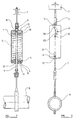
- the supporting device which is the preferred embodiment of this invention comprises a helical compression spring 1 located within a cylindrical housing 3, the device being designed to support a load 8, typically but not exclusively a pipe, from a fixed support structure 7.
- a rod 5 is secured to an upper spring cap 2 mounted on an upper end portion of the spring 1, the lower end of the spring being secured to a base cap 4.
- a top plate 15 of the housing is provided with a lug 16 for attachment, through a stirrup hanger 6, to the support structure 7.
- the base cap 4 is provided with a pair of diametral trunnions 9 which are located in axially extending slots 12 in the housing 3.
- the base cap is threaded on to a threaded sleeve adjuster having a double flanged lower end 17 which embraces the base plate 14, enabling the sleeve 13 to be rotated through a central aperture in the base plate 14 whilst locating the sleeve axially, the load rod 5 passing freely through the base cap 4 and base plate 14.
- the position of the base cap may be adjusted axially by rotation of the adjuster 13 to vary the reactive force provided by the device, and hence enabling the load bearing capacity of the device to be adjusted.
- the pipe load 8 will move vertically during plant operation to any position between the high position shown in Figure 2 and the low position shown in Figure 3.
- the pipe load 8 is hung from the load rod 5 and as the load moves downwardly the load rod pulls the upper cap 2 downwardly, to compress the spring.
- the device which is according to this invention comprises means to compensate for variations in the force applied by the spring to the load as the load moves axially, and specifically is operative to negate the variation of the spring reaction of the spring as the spring is compressed and relaxed.
- the compensation means comprises a pair of trunnions 10 extending diametrally from the cap 2 which coact with cam surfaces formed as a curved cam track 11 in the wall of the cylindrical housing the trunnions sliding or rolling along the cam track.
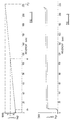
- the helical compression spring 1 is arranged to balance the pipe load 8 at the mid point M of its range of axial movement so that when the pipe load is at the high position as shown in Figure 2, the resilience of the spring in compression would be insufficient to support the pipe load, as is evident from Figure 1.
- the additional support provided on movement of the load from the positions M1 to M as the spring is compressed towards the position M is provided by requiring the load as it moves downwardly to perform additional work caused by the spring being wound up to develop a torsional force to urge the trunnions into engagement with the face 11a of the cam track 11.
- the trunnions engage with the face 11a of the cam track 11, providing an upward force acting on the trunnions.
- the rate at which this work is required to be performed is dependent upon the angle of the cam face 11a, and as the spring is compressed towards its median point, the work required to be performed to produce a constant balancing force reduces, and at the median point, the cam face 11a is parallel to the longitudinal axis.
- the additional force X may be applied in the upward direction to the trunnions by the reactive force acting vertically on the trunnions (the horizontal components cancelling out), the force reducing as the load moves towards its median points.
- the counterbalancing force applied to the load by the support device may be adjusted to a constant level Z - that is, the level obtained by the spring at its median point - throughout the range of travel of the load.
- Z - the level obtained by the spring at its median point - throughout the range of travel of the load.
- a cam track is utilised which has a shape which will produce a substantially constant supporting force acting against the load throughout the range of movement of the spring, since the cam surface profile will determine the supporting effort applied to the load rod 5, within limits, any support pattern may be obtained.
- a bias may be provided to ensure that the load will tend to move to a preferred position.
- the spring is a compression spring, if desired the same effect may be achieved when a tension spring is utilised.
Description
Claims (4)
- A force applying device comprising, a housing adapted to be secured to a supporting surface or a load (8), a spring (1) supported by the housing (3), and means (5) to enable the load (8) to be secured to the spring (1) or the housing respectively to be supported thereby, compensating means (10, 11) which provides a torsionally developed reaction axial force to be added to the axial reaction force of the spring characterised by the compensating means comprising a trunnion means (10) secured to the spring (1) located within the housing and a curved cam track (11) provided by the wall of the housing, and when the load moves, the trunnion means moving along the cam track (11) so that the magnitude and direction of the additional axial force varies in dependence upon load movement, the shape of the cam track (11) being arranged so that the change in magnitude and direction of the additional reactional force as the load moves, in both directions compensates for variations in the reactive force provided by the spring (1) during movement of the load (8) towards and away a median point (M), where the spring (1) balances.
- A device according to claim 1 characterised in that the compensating means (10,11) is operative to cause the device to produce a substantially constant reactive force on axial movement of the load (8).
- A device according to claim 1 or claim 2 characterised in that when the load is applied, the compensating means (10, 11) is operative to increase the magnitude of the additional axial force as the load (8) moves in one direction towards one end of its range of movement, and is operative to decrease the magnitude of the additional axial force as the load moves in an opposite direction towards the other end of its range of movement.
- A device according to any one of claims 1 to 3 characterised in that the housing (3), is cylindrical and the compensating means comprising a pair of trunnions (10) secured to the spring (1) and projecting oppositely diametrically therefrom, said trunnions (10) engaging with one of a pair of diametrically opposed cam tracks (11) provided by the wall of the cylindrical housing (3), the cam tracks (11) extending around the longitudinal axis such that the trunnions (10) rotate about the longitudinal axis as the load (8) supported by the spring (1) moves longitudinally.
Applications Claiming Priority (3)
| Application Number | Priority Date | Filing Date | Title |
|---|---|---|---|
| GB939321543A GB9321543D0 (en) | 1993-10-19 | 1993-10-19 | Resilient spring devices |
| GB9321543 | 1993-10-19 | ||
| PCT/GB1994/002222 WO1995011398A1 (en) | 1993-10-19 | 1994-10-12 | Force applying devices |
Publications (2)
| Publication Number | Publication Date |
|---|---|
| EP0724696A1 EP0724696A1 (en) | 1996-08-07 |
| EP0724696B1 true EP0724696B1 (en) | 1999-03-24 |
Family
ID=10743779
Family Applications (1)
| Application Number | Title | Priority Date | Filing Date |
|---|---|---|---|
| EP94928972A Expired - Lifetime EP0724696B1 (en) | 1993-10-19 | 1994-10-12 | Force applying devices |
Country Status (8)
| Country | Link |
|---|---|
| EP (1) | EP0724696B1 (en) |
| AU (1) | AU7819294A (en) |
| CZ (1) | CZ111796A3 (en) |
| DE (1) | DE69417431D1 (en) |
| GB (1) | GB9321543D0 (en) |
| TW (1) | TW268997B (en) |
| WO (1) | WO1995011398A1 (en) |
| ZA (1) | ZA948006B (en) |
Families Citing this family (3)
| Publication number | Priority date | Publication date | Assignee | Title |
|---|---|---|---|---|
| CZ289120B6 (en) * | 1999-09-15 | 2001-11-14 | Gdv, A. S. | Device inducing constant force |
| CN105840914B (en) * | 2016-06-07 | 2018-04-17 | 周梅荣 | A kind of damping device of antimony glycol feedstock transportation pipeline |
| CN112594311A (en) * | 2020-12-21 | 2021-04-02 | 中车眉山车辆有限公司 | Symmetrical spring device with adjustable tension |
Family Cites Families (3)
| Publication number | Priority date | Publication date | Assignee | Title |
|---|---|---|---|---|
| US3157392A (en) * | 1962-05-03 | 1964-11-17 | Kitamura Kenzaburo | Spring apparatus for the suspension of vehicles |
| DE3214687A1 (en) * | 1982-04-16 | 1983-10-27 | Gerb Gesellschaft für Isolierung mbH & Co KG, 1000 Berlin | Device for the sprung retention of pipelines and the like |
| GB8430562D0 (en) * | 1984-12-04 | 1985-01-09 | Carpenter & Paterson Ltd | Spring support device |
-
1993
- 1993-10-19 GB GB939321543A patent/GB9321543D0/en active Pending
-
1994
- 1994-10-11 TW TW083109372A patent/TW268997B/zh active
- 1994-10-12 DE DE69417431T patent/DE69417431D1/en not_active Expired - Lifetime
- 1994-10-12 WO PCT/GB1994/002222 patent/WO1995011398A1/en not_active Application Discontinuation
- 1994-10-12 EP EP94928972A patent/EP0724696B1/en not_active Expired - Lifetime
- 1994-10-12 AU AU78192/94A patent/AU7819294A/en not_active Abandoned
- 1994-10-12 CZ CZ961117A patent/CZ111796A3/en unknown
- 1994-10-13 ZA ZA948006A patent/ZA948006B/en unknown
Also Published As
| Publication number | Publication date |
|---|---|
| CZ111796A3 (en) | 1996-10-16 |
| EP0724696A1 (en) | 1996-08-07 |
| AU7819294A (en) | 1995-05-08 |
| WO1995011398A1 (en) | 1995-04-27 |
| GB9321543D0 (en) | 1993-12-08 |
| ZA948006B (en) | 1996-06-11 |
| DE69417431D1 (en) | 1999-04-29 |
| TW268997B (en) | 1996-01-21 |
Similar Documents
| Publication | Publication Date | Title |
|---|---|---|
| US4726253A (en) | Torque counterbalancing mechanisms | |
| EP1165268B1 (en) | Tool for automatic roll folding | |
| SE521863C2 (en) | Castor | |
| US4495826A (en) | Vibratory apparatus | |
| EP1824693B1 (en) | Anti-roll/pitch system for use in a vehicle and vehicle equipped with such system | |
| US4598601A (en) | Means for counterbalancing mass in mechanisms such as a robot arm | |
| US5165297A (en) | Remote controlled micromanipulator | |
| JPH0154582B2 (en) | ||
| EP0724696B1 (en) | Force applying devices | |
| US6539975B2 (en) | Arrangement for maintaining gas in a variable volume container at a constant pressure | |
| US4617832A (en) | Vibratory apparatus having variable lead angle and force | |
| CA2221336C (en) | Cam and roller overcenter handle mechanism | |
| AU2003214444B2 (en) | Improvements in or relating to tiltable mountings for payloads | |
| AU5403598A (en) | Improvements in or relating to rotary load counterbalancing mechanisms | |
| US4181343A (en) | Oscillating movement damping means intended for pivotally suspended hoisting gear | |
| CA1194506A (en) | Weight responsive rotary retardation device | |
| US3048359A (en) | Constant support pipe hanger | |
| CN113586808A (en) | Lever type adjustable load supporting and hanging frame | |
| US4328944A (en) | Load supporting device | |
| RU2239589C2 (en) | Container | |
| US4458514A (en) | Position control of piston-cylinder device | |
| GB2076502A (en) | A Load Supporting Spring System | |
| CN113738818B (en) | Two-dimensional vibration isolator capable of exciting and isolating any displacement in opposite surface | |
| JPH0530803Y2 (en) | ||
| US2724587A (en) | Suspension device of variable flexibility for vehicles |
Legal Events
| Date | Code | Title | Description |
|---|---|---|---|
| PUAI | Public reference made under article 153(3) epc to a published international application that has entered the european phase |
Free format text: ORIGINAL CODE: 0009012 |
|
| 17P | Request for examination filed |
Effective date: 19960416 |
|
| AK | Designated contracting states |
Kind code of ref document: A1 Designated state(s): BE DE ES FR GB IT NL |
|
| 17Q | First examination report despatched |
Effective date: 19961002 |
|
| GRAG | Despatch of communication of intention to grant |
Free format text: ORIGINAL CODE: EPIDOS AGRA |
|
| GRAG | Despatch of communication of intention to grant |
Free format text: ORIGINAL CODE: EPIDOS AGRA |
|
| GRAH | Despatch of communication of intention to grant a patent |
Free format text: ORIGINAL CODE: EPIDOS IGRA |
|
| GRAH | Despatch of communication of intention to grant a patent |
Free format text: ORIGINAL CODE: EPIDOS IGRA |
|
| GRAA | (expected) grant |
Free format text: ORIGINAL CODE: 0009210 |
|
| AK | Designated contracting states |
Kind code of ref document: B1 Designated state(s): BE DE ES FR GB IT NL |
|
| PG25 | Lapsed in a contracting state [announced via postgrant information from national office to epo] |
Ref country code: NL Free format text: LAPSE BECAUSE OF FAILURE TO SUBMIT A TRANSLATION OF THE DESCRIPTION OR TO PAY THE FEE WITHIN THE PRESCRIBED TIME-LIMIT Effective date: 19990324 Ref country code: IT Free format text: LAPSE BECAUSE OF FAILURE TO SUBMIT A TRANSLATION OF THE DESCRIPTION OR TO PAY THE FEE WITHIN THE PRE;WARNING: LAPSES OF ITALIAN PATENTS WITH EFFECTIVE DATE BEFORE 2007 MAY HAVE OCCURRED AT ANY TIME BEFORE 2007. THE CORRECT EFFECTIVE DATE MAY BE DIFFERENT FROM THE ONE RECORDED.SCRIBED TIME-LIMIT Effective date: 19990324 Ref country code: FR Free format text: LAPSE BECAUSE OF FAILURE TO SUBMIT A TRANSLATION OF THE DESCRIPTION OR TO PAY THE FEE WITHIN THE PRESCRIBED TIME-LIMIT Effective date: 19990324 Ref country code: ES Free format text: THE PATENT HAS BEEN ANNULLED BY A DECISION OF A NATIONAL AUTHORITY Effective date: 19990324 Ref country code: BE Free format text: LAPSE BECAUSE OF FAILURE TO SUBMIT A TRANSLATION OF THE DESCRIPTION OR TO PAY THE FEE WITHIN THE PRESCRIBED TIME-LIMIT Effective date: 19990324 |
|
| REF | Corresponds to: |
Ref document number: 69417431 Country of ref document: DE Date of ref document: 19990429 |
|
| PG25 | Lapsed in a contracting state [announced via postgrant information from national office to epo] |
Ref country code: DE Free format text: LAPSE BECAUSE OF FAILURE TO SUBMIT A TRANSLATION OF THE DESCRIPTION OR TO PAY THE FEE WITHIN THE PRESCRIBED TIME-LIMIT Effective date: 19990625 |
|
| EN | Fr: translation not filed | ||
| NLV1 | Nl: lapsed or annulled due to failure to fulfill the requirements of art. 29p and 29m of the patents act | ||
| PLBE | No opposition filed within time limit |
Free format text: ORIGINAL CODE: 0009261 |
|
| STAA | Information on the status of an ep patent application or granted ep patent |
Free format text: STATUS: NO OPPOSITION FILED WITHIN TIME LIMIT |
|
| 26N | No opposition filed | ||
| REG | Reference to a national code |
Ref country code: GB Ref legal event code: IF02 |
|
| PGFP | Annual fee paid to national office [announced via postgrant information from national office to epo] |
Ref country code: GB Payment date: 20041006 Year of fee payment: 11 |
|
| PG25 | Lapsed in a contracting state [announced via postgrant information from national office to epo] |
Ref country code: GB Free format text: LAPSE BECAUSE OF NON-PAYMENT OF DUE FEES Effective date: 20051012 |
|
| GBPC | Gb: european patent ceased through non-payment of renewal fee |
Effective date: 20051012 |