EP0724684B1 - Adaptive manifold tuning - Google Patents
Adaptive manifold tuning Download PDFInfo
- Publication number
- EP0724684B1 EP0724684B1 EP94926744A EP94926744A EP0724684B1 EP 0724684 B1 EP0724684 B1 EP 0724684B1 EP 94926744 A EP94926744 A EP 94926744A EP 94926744 A EP94926744 A EP 94926744A EP 0724684 B1 EP0724684 B1 EP 0724684B1
- Authority
- EP
- European Patent Office
- Prior art keywords
- engine
- induction air
- intake passage
- neck
- induction
- Prior art date
- Legal status (The legal status is an assumption and is not a legal conclusion. Google has not performed a legal analysis and makes no representation as to the accuracy of the status listed.)
- Expired - Lifetime
Links
- 230000003044 adaptive effect Effects 0.000 title description 10
- 230000006698 induction Effects 0.000 claims description 34
- 238000002485 combustion reaction Methods 0.000 claims description 14
- 238000000034 method Methods 0.000 claims 3
- 230000008520 organization Effects 0.000 abstract 1
- 230000000694 effects Effects 0.000 description 2
- 238000011144 upstream manufacturing Methods 0.000 description 2
- 238000010276 construction Methods 0.000 description 1
- 238000011217 control strategy Methods 0.000 description 1
- 238000010586 diagram Methods 0.000 description 1
- 238000005516 engineering process Methods 0.000 description 1
- 238000004519 manufacturing process Methods 0.000 description 1
Images


Classifications
-
- F—MECHANICAL ENGINEERING; LIGHTING; HEATING; WEAPONS; BLASTING
- F02—COMBUSTION ENGINES; HOT-GAS OR COMBUSTION-PRODUCT ENGINE PLANTS
- F02B—INTERNAL-COMBUSTION PISTON ENGINES; COMBUSTION ENGINES IN GENERAL
- F02B27/00—Use of kinetic or wave energy of charge in induction systems, or of combustion residues in exhaust systems, for improving quantity of charge or for increasing removal of combustion residues
- F02B27/02—Use of kinetic or wave energy of charge in induction systems, or of combustion residues in exhaust systems, for improving quantity of charge or for increasing removal of combustion residues the systems having variable, i.e. adjustable, cross-sectional areas, chambers of variable volume, or like variable means
- F02B27/0226—Use of kinetic or wave energy of charge in induction systems, or of combustion residues in exhaust systems, for improving quantity of charge or for increasing removal of combustion residues the systems having variable, i.e. adjustable, cross-sectional areas, chambers of variable volume, or like variable means characterised by the means generating the charging effect
- F02B27/0247—Plenum chambers; Resonance chambers or resonance pipes
- F02B27/0263—Plenum chambers; Resonance chambers or resonance pipes the plenum chamber and at least one of the intake ducts having a common wall, and the intake ducts wrap partially around the plenum chamber, i.e. snail-type
-
- F—MECHANICAL ENGINEERING; LIGHTING; HEATING; WEAPONS; BLASTING
- F02—COMBUSTION ENGINES; HOT-GAS OR COMBUSTION-PRODUCT ENGINE PLANTS
- F02B—INTERNAL-COMBUSTION PISTON ENGINES; COMBUSTION ENGINES IN GENERAL
- F02B27/00—Use of kinetic or wave energy of charge in induction systems, or of combustion residues in exhaust systems, for improving quantity of charge or for increasing removal of combustion residues
-
- F—MECHANICAL ENGINEERING; LIGHTING; HEATING; WEAPONS; BLASTING
- F02—COMBUSTION ENGINES; HOT-GAS OR COMBUSTION-PRODUCT ENGINE PLANTS
- F02B—INTERNAL-COMBUSTION PISTON ENGINES; COMBUSTION ENGINES IN GENERAL
- F02B27/00—Use of kinetic or wave energy of charge in induction systems, or of combustion residues in exhaust systems, for improving quantity of charge or for increasing removal of combustion residues
- F02B27/008—Resonance charging
-
- F—MECHANICAL ENGINEERING; LIGHTING; HEATING; WEAPONS; BLASTING
- F02—COMBUSTION ENGINES; HOT-GAS OR COMBUSTION-PRODUCT ENGINE PLANTS
- F02B—INTERNAL-COMBUSTION PISTON ENGINES; COMBUSTION ENGINES IN GENERAL
- F02B27/00—Use of kinetic or wave energy of charge in induction systems, or of combustion residues in exhaust systems, for improving quantity of charge or for increasing removal of combustion residues
- F02B27/02—Use of kinetic or wave energy of charge in induction systems, or of combustion residues in exhaust systems, for improving quantity of charge or for increasing removal of combustion residues the systems having variable, i.e. adjustable, cross-sectional areas, chambers of variable volume, or like variable means
-
- F—MECHANICAL ENGINEERING; LIGHTING; HEATING; WEAPONS; BLASTING
- F02—COMBUSTION ENGINES; HOT-GAS OR COMBUSTION-PRODUCT ENGINE PLANTS
- F02B—INTERNAL-COMBUSTION PISTON ENGINES; COMBUSTION ENGINES IN GENERAL
- F02B27/00—Use of kinetic or wave energy of charge in induction systems, or of combustion residues in exhaust systems, for improving quantity of charge or for increasing removal of combustion residues
- F02B27/02—Use of kinetic or wave energy of charge in induction systems, or of combustion residues in exhaust systems, for improving quantity of charge or for increasing removal of combustion residues the systems having variable, i.e. adjustable, cross-sectional areas, chambers of variable volume, or like variable means
- F02B27/0205—Use of kinetic or wave energy of charge in induction systems, or of combustion residues in exhaust systems, for improving quantity of charge or for increasing removal of combustion residues the systems having variable, i.e. adjustable, cross-sectional areas, chambers of variable volume, or like variable means characterised by the charging effect
- F02B27/021—Resonance charging
-
- F—MECHANICAL ENGINEERING; LIGHTING; HEATING; WEAPONS; BLASTING
- F02—COMBUSTION ENGINES; HOT-GAS OR COMBUSTION-PRODUCT ENGINE PLANTS
- F02B—INTERNAL-COMBUSTION PISTON ENGINES; COMBUSTION ENGINES IN GENERAL
- F02B27/00—Use of kinetic or wave energy of charge in induction systems, or of combustion residues in exhaust systems, for improving quantity of charge or for increasing removal of combustion residues
- F02B27/02—Use of kinetic or wave energy of charge in induction systems, or of combustion residues in exhaust systems, for improving quantity of charge or for increasing removal of combustion residues the systems having variable, i.e. adjustable, cross-sectional areas, chambers of variable volume, or like variable means
- F02B27/0226—Use of kinetic or wave energy of charge in induction systems, or of combustion residues in exhaust systems, for improving quantity of charge or for increasing removal of combustion residues the systems having variable, i.e. adjustable, cross-sectional areas, chambers of variable volume, or like variable means characterised by the means generating the charging effect
- F02B27/0247—Plenum chambers; Resonance chambers or resonance pipes
-
- Y—GENERAL TAGGING OF NEW TECHNOLOGICAL DEVELOPMENTS; GENERAL TAGGING OF CROSS-SECTIONAL TECHNOLOGIES SPANNING OVER SEVERAL SECTIONS OF THE IPC; TECHNICAL SUBJECTS COVERED BY FORMER USPC CROSS-REFERENCE ART COLLECTIONS [XRACs] AND DIGESTS
- Y02—TECHNOLOGIES OR APPLICATIONS FOR MITIGATION OR ADAPTATION AGAINST CLIMATE CHANGE
- Y02T—CLIMATE CHANGE MITIGATION TECHNOLOGIES RELATED TO TRANSPORTATION
- Y02T10/00—Road transport of goods or passengers
- Y02T10/10—Internal combustion engine [ICE] based vehicles
- Y02T10/12—Improving ICE efficiencies
Definitions
- This invention relates to induction systems for internal combustion engines, and it is particularly concerned with tuning of engine manifolds by means of resonators.
- EP-A2-182 223 teaches the changing of the length of the intake passage or runners by means of one or more butterfly valves according to engine speed. This has the effect of reducing the length of air flow into the engine for increasing the amount of air into the engine during heavy load.
- EP-A- 111336 discloses a HELMHOLTZ resonator with an obturator in its neck actuated electrically according to the engine speed, so as to increase the output of the internal combustion engine, the resonator being in connection with the induction air passage.
- the obturator is used for changing the cross sectional area of the neck as a function of the engine speed.
- the resonator is being used to modify engine torque output for better engine performance (see p. 1 ,17).
- Typical intake manifold geometries provide an engine torque-speed characteristic that has a peak torque at a certain engine speed. Over a range of engine speeds beyond that certain engine speed, the torque dips.
- the present invention is directed toward reducing, or even eliminating, such a dip. Contrary to the prior art, this invention introduces noise into the system to re-enforce the pressure pulse which is traveling back into the engine when the intake valve is opened to increase the volume of flow into the engine. This re-enforcement has the effect of supercharging the air into the cylinder(s) to increase the torque output of the engine.
- this invention as defined with the features according to claims 1 and 6, teaches holding the length of the neck and changing its cross-sectional area as a function of engine speed, with a specific mechanism (see 2 part of claim 1, 6).
- This system has an engine speed range from 1600 to 4000 rpm with Fig. 6 showing an engine speed from 1200 to 3600 rpm or a range of 2400 rpm.
- Fig. 1 is a somewhat schematic diagram of an internal combustion engine induction system which includes the adaptive manifold tuning of the present invention.
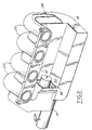
- Fig. 2 is a perspective view of an induction system having the adaptive manifold tuning.
- Fig. 3 is a fragmentary view of a portion of Fig. 2 with certain portions having been sectioned away to illustrate internal features.
- Fig. 4 is a transverse view as taken in the direction of arrows 4-4 in Fig. 3.
- Fig. 5 is a perspective view of another embodiment.
- Fig. 6 is a graph that illustrates representative improvement that can be obtained with the adaptive manifold tuning of the invention.
- FIG. 1 A representative induction system 10 for an internal combustion engine 12 is shown in Fig. 1.
- Induction system 10 comprises an induction air intake passage 14 that contains a butterfly-valve type throttle 16 for selectively throttling induction air flow.
- Intake passage 14 leads to a plenum chamber 18, and from plenum chamber 18 there are a number of runners 20 for delivering induction air to individual combustion chambers of engine 12.
- the adaptive manifold tuning of the present invention comprises a Helmholtz resonator 22 associated with induction system 10.
- Helmholtz resonator 22 comprises a resonator chamber 24 that is placed in communication with intake passage 14 at a location that is downstream of throttle 16 but upstream of plenum chamber 18. Communication is established by means of a neck 26 of Helmholtz resonator 22.
- the invention relates to means for selectively setting the effective transverse cross-sectional area of communication that neck 26 provides between chamber 24 and intake passage 14.
- This means comprises an obturator, or valve, 28 that is operated by an actuator 30, which is itself operated in accordance with one or more parameters representative of the operation of engine 12.
- actuator 30 is controlled as a function only of speed of engine 12, but it is possible that other control strategies may involve one or more other parameters with or without engine speed.
- Engine speed information may be derived from any conventional source of engine speed that may be available.
- the Helmholtz principle is a function of not only the effective transverse cross-sectional area of communication provided by neck 26, but also of the length of the neck and the volume of resonator chamber 24, the torque improvement that can be obtained in any given engine is a function of three parameters.
- the volume of resonator chamber 24 is fixed, as is the length of neck 26, but it is contemplated that more elaborate tuning systems could have means to vary these parameters as well as the effective transverse cross-sectional area of communication provided by neck 26.
- FIG. 2-4 depict constructional detail for the schematic system described in Fig. 1.
- Intake passage 14 is shown in Figs. 2-4 as a circular walled tube that merges axially into one end of plenum chamber 18.
- Plenum chamber 18 and resonator chamber 24 are arranged generally side-by-side; however, resonator chamber 24 axially overlaps both intake passage 14 and plenum chamber 18 such that a portion of intake passage 14 immediately adjoining plenum chamber 18 is juxtaposed generally side-by-side with the portion of resonator chamber 24 that overlaps it, while the remaining portion of resonator chamber 24 is juxtaposed side-by-side with plenum chamber 18.
- Runners 20 extend from a side of plenum chamber 18 to wrap partially around a side of resonator chamber 24.
- the runners terminate in a mounting flange 32 that attaches to engine 12.
- Flange 32 and an immediately joining short segment of each runner overhang from resonator chamber 24 so as to overlie both plenum chamber 18 and air intake passage 14, as perhaps best seen in Fig. 4.
- Obturator 28 is a slide that is contained within a compartment 34 that forms neck 26.
- the location where the neck opens to intake passage 14 is designated 36 while the location where the neck opens to resonator chamber 24 is designated 38.
- the height of the neck is designated 39.
- the obturator selectively obturates the neck opening in accordance with the extent that it is slid in a plane that is transverse to the length of the neck.
- Compartment 34 is large enough to contain obturator 28 and to accommodate the range over which it can slide.
- Obturator 28 comprises a flat planar body 40 of generally rectangular shape that is bounded on three sides by a flange 42. The flange provides guidance for the sliding motion of the obturator within the compartment.
- flange 42 is curved to match the curvature of the exterior of a portion of a wall 44 that extends from opening 36 in the direction of the plenum chamber to form portions of the wall of intake passage 14 and plenum chamber 18 where the two merge.
- obturator 28 can be selectively extended and retracted in a direction parallel to the transverse cross-sectional area of communication that is provided by neck 26 to thereby set the effective transverse cross-sectional area of communication that the neck provides between resonator chamber 24 and intake passage 14.
- actuator 30 Positioning of obturator 28 is accomplished by a rod 46 of actuator 30.
- actuator 30 may be a vacuum operated servo-type actuator as perhaps best seen in Fig. 3.
- Actuator 30 is mounted in a wall member 48 that forms a closure for that end of compartment 34.
- intake passage 14, plenum chamber 18, runners 20, and Helmholtz resonator 22 may be fabricated as a unitary part.
- Obturator 28 and actuator 30 are assembled into the unitary part.
- the Helmholtz resonator with adaptive tuning feature of the invention may be embodied in a separate assembly that can be in-line mounted in the air intake passage.
- An example of such an assembly is shown in Fig. 5. It comprises flanges 50, 52 providing for the in-line mounting of the assembly in the air intake passage, and a body 54 that is between these flanges and houses the obturator, while forming the neck of the Helmholtz resonator leading to the resonator chamber.
- the actuator rod 46 extends through body 54 to the actuator, which is not shown, but is external to the body.
- Helmholtz resonator While it is preferred that the Helmholtz resonator have communication with the induction system downstream of the throttle, it is possible that such communication may take place upstream of the throttle.
- An advantage of having the resonator communicate with the induction system downstream of the throttle is that at part throttle conditions, the torque curve is significantly improved with lower loss in wide open throttle torque.
- FIG. 6 graphs engine output torque in non-dimensional units versus engine speed.
- a first graph plot 60 is a baseline for a particular engine without the adaptive manifold tuning feature of the invention.
- a second graph plot 62 is for the same engine but with the adaptive tuning feature and with a particular size Helmholtz resonator chamber.
- a third graph plot 66 is for the same engine also with adaptive tuning feature but with a different size Helmholtz resonator chamber. It can be seen that definite torque improvements can be obtained with the invention. Obviously, the nature and extent of improvement will depend on a number of factors, and in any given application of the invention, it may be necessary to vary different factors to get the best improvement that is obtainable.
Landscapes
- Engineering & Computer Science (AREA)
- Chemical & Material Sciences (AREA)
- Combustion & Propulsion (AREA)
- Mechanical Engineering (AREA)
- General Engineering & Computer Science (AREA)
- Characterised By The Charging Evacuation (AREA)
Abstract
Description
- This invention relates to induction systems for internal combustion engines, and it is particularly concerned with tuning of engine manifolds by means of resonators.
- It is well known to employ resonators to tune the manifolds of internal combustion engines, especially engines that are used for powering automotive vehicles. Commonly assigned U.S. Patent No. 5,162,621, "internal Sidebranch Resonator" having a priority date of 16.10.90, discloses the use of a Helmholtz resonator to tune the manifold of an engine by attenuating the noise that propagates through the manifold of the engine; the Helmholtz resonator is non adjustable once it is manufactured.
- EP-A2-182 223 teaches the changing of the length of the intake passage or runners by means of one or more butterfly valves according to engine speed. This has the effect of reducing the length of air flow into the engine for increasing the amount of air into the engine during heavy load.
- EP-A- 111336 (figures) discloses a HELMHOLTZ resonator with an obturator in its neck actuated electrically according to the engine speed, so as to increase the output of the internal combustion engine, the resonator being in connection with the induction air passage. The obturator is used for changing the cross sectional area of the neck as a function of the engine speed. The resonator is being used to modify engine torque output for better engine performance (see p. 1 ,17).
- Typical intake manifold geometries provide an engine torque-speed characteristic that has a peak torque at a certain engine speed. Over a range of engine speeds beyond that certain engine speed, the torque dips. The present invention is directed toward reducing, or even eliminating, such a dip. Contrary to the prior art, this invention introduces noise into the system to re-enforce the pressure pulse which is traveling back into the engine when the intake valve is opened to increase the volume of flow into the engine. This re-enforcement has the effect of supercharging the air into the cylinder(s) to increase the torque output of the engine. To do this, this invention, as defined with the features according to claims 1 and 6, teaches holding the length of the neck and changing its cross-sectional area as a function of engine speed, with a specific mechanism (see 2 part of claim 1, 6). This system has an engine speed range from 1600 to 4000 rpm with Fig. 6 showing an engine speed from 1200 to 3600 rpm or a range of 2400 rpm.
- Fig. 1 is a somewhat schematic diagram of an internal combustion engine induction system which includes the adaptive manifold tuning of the present invention.
- Fig. 2 is a perspective view of an induction system having the adaptive manifold tuning.
- Fig. 3 is a fragmentary view of a portion of Fig. 2 with certain portions having been sectioned away to illustrate internal features.
- Fig. 4 is a transverse view as taken in the direction of arrows 4-4 in Fig. 3.
- Fig. 5 is a perspective view of another embodiment.
- Fig. 6 is a graph that illustrates representative improvement that can be obtained with the adaptive manifold tuning of the invention.
- A representative induction system 10 for an
internal combustion engine 12 is shown in Fig. 1. Induction system 10 comprises an inductionair intake passage 14 that contains a butterfly-valve type throttle 16 for selectively throttling induction air flow.Intake passage 14 leads to aplenum chamber 18, and fromplenum chamber 18 there are a number ofrunners 20 for delivering induction air to individual combustion chambers ofengine 12. - The adaptive manifold tuning of the present invention comprises a Helmholtz
resonator 22 associated with induction system 10. Helmholtzresonator 22 comprises aresonator chamber 24 that is placed in communication withintake passage 14 at a location that is downstream ofthrottle 16 but upstream ofplenum chamber 18. Communication is established by means of aneck 26 of Helmholtzresonator 22. The invention relates to means for selectively setting the effective transverse cross-sectional area of communication thatneck 26 provides betweenchamber 24 andintake passage 14. This means comprises an obturator, or valve, 28 that is operated by anactuator 30, which is itself operated in accordance with one or more parameters representative of the operation ofengine 12. In the preferred embodiment,actuator 30 is controlled as a function only of speed ofengine 12, but it is possible that other control strategies may involve one or more other parameters with or without engine speed. Engine speed information may be derived from any conventional source of engine speed that may be available. - By selectively setting the effective transverse cross-sectional area of communication that
neck 26 provides betweenchamber 24 andintake passage 14, it is possible for a given engine to develop a noticeable increase in torque output over that which might otherwise be obtained in the absence of adaptive manifold tuning. Since the Helmholtz principle is a function of not only the effective transverse cross-sectional area of communication provided byneck 26, but also of the length of the neck and the volume ofresonator chamber 24, the torque improvement that can be obtained in any given engine is a function of three parameters. In the present embodiment, the volume ofresonator chamber 24 is fixed, as is the length ofneck 26, but it is contemplated that more elaborate tuning systems could have means to vary these parameters as well as the effective transverse cross-sectional area of communication provided byneck 26. - Figs. 2-4 depict constructional detail for the schematic system described in Fig. 1. Like reference numerals designate like parts in Fig. 1-4.
Intake passage 14 is shown in Figs. 2-4 as a circular walled tube that merges axially into one end ofplenum chamber 18.Plenum chamber 18 andresonator chamber 24 are arranged generally side-by-side; however,resonator chamber 24 axially overlaps bothintake passage 14 andplenum chamber 18 such that a portion ofintake passage 14 immediately adjoiningplenum chamber 18 is juxtaposed generally side-by-side with the portion ofresonator chamber 24 that overlaps it, while the remaining portion ofresonator chamber 24 is juxtaposed side-by-side withplenum chamber 18. -
Runners 20 extend from a side ofplenum chamber 18 to wrap partially around a side ofresonator chamber 24. The runners terminate in amounting flange 32 that attaches toengine 12.Flange 32 and an immediately joining short segment of each runner overhang fromresonator chamber 24 so as to overlie bothplenum chamber 18 andair intake passage 14, as perhaps best seen in Fig. 4. -
Obturator 28 is a slide that is contained within acompartment 34 that formsneck 26. The location where the neck opens tointake passage 14 is designated 36 while the location where the neck opens toresonator chamber 24 is designated 38. The height of the neck is designated 39. The obturator selectively obturates the neck opening in accordance with the extent that it is slid in a plane that is transverse to the length of the neck.Compartment 34 is large enough to containobturator 28 and to accommodate the range over which it can slide.Obturator 28 comprises a flatplanar body 40 of generally rectangular shape that is bounded on three sides by a flange 42. The flange provides guidance for the sliding motion of the obturator within the compartment. Where it confrontsintake passage 14 andplenum chamber 18, flange 42 is curved to match the curvature of the exterior of a portion of awall 44 that extends from opening 36 in the direction of the plenum chamber to form portions of the wall ofintake passage 14 andplenum chamber 18 where the two merge. With this arrangement,obturator 28 can be selectively extended and retracted in a direction parallel to the transverse cross-sectional area of communication that is provided byneck 26 to thereby set the effective transverse cross-sectional area of communication that the neck provides betweenresonator chamber 24 andintake passage 14. - Positioning of
obturator 28 is accomplished by arod 46 ofactuator 30. For example,actuator 30 may be a vacuum operated servo-type actuator as perhaps best seen in Fig. 3.Actuator 30 is mounted in awall member 48 that forms a closure for that end ofcompartment 34. - By using a fabricating technology, such as lost core fabrication,
intake passage 14,plenum chamber 18,runners 20, and Helmholtzresonator 22 may be fabricated as a unitary part.Obturator 28 andactuator 30 are assembled into the unitary part. - Where an induction system does not comprise such unitary construction, the Helmholtz resonator with adaptive tuning feature of the invention may be embodied in a separate assembly that can be in-line mounted in the air intake passage. An example of such an assembly is shown in Fig. 5. It comprises
flanges body 54 that is between these flanges and houses the obturator, while forming the neck of the Helmholtz resonator leading to the resonator chamber. Theactuator rod 46 extends throughbody 54 to the actuator, which is not shown, but is external to the body. While it is preferred that the Helmholtz resonator have communication with the induction system downstream of the throttle, it is possible that such communication may take place upstream of the throttle. An advantage of having the resonator communicate with the induction system downstream of the throttle is that at part throttle conditions, the torque curve is significantly improved with lower loss in wide open throttle torque. - Fig. 6 graphs engine output torque in non-dimensional units versus engine speed. A first graph plot 60 is a baseline for a particular engine without the adaptive manifold tuning feature of the invention. A second graph plot 62 is for the same engine but with the adaptive tuning feature and with a particular size Helmholtz resonator chamber. A third graph plot 66 is for the same engine also with adaptive tuning feature but with a different size Helmholtz resonator chamber. It can be seen that definite torque improvements can be obtained with the invention. Obviously, the nature and extent of improvement will depend on a number of factors, and in any given application of the invention, it may be necessary to vary different factors to get the best improvement that is obtainable.
Claims (7)
- An internal combustion engine having an active manifold tuning system, a system for increasing the induction air flow to the engine to improve the engine-torque speed curve, the system comprisingan induction air intake passage containing throttle valve means for selectively throttling induction air flow;plenum chamber means for receiving the induction air flow that has passed through said induction air intake passage;runners leading from said plenum chamber means for delivering induction air to individual combustion chambers of an engine;a Helmholtz resonator comprising a resonator chamber that is connected to said induction air intake passage by means of a neck;an actuator responsive to engine speed; andobturator means operated by said actuator for selectively setting the effective transverse cross section area of the neck;characterized by
the obturator comprising a slide guided, at least in part on the exterior of a wall portion of at least one of the induction air intake passage and the plenum chamber. - An internal combustion engine induction system as set forth in claim 1 characterized further in that said obturator means comprises a slide that is selectively positionable by said actuator means parallel to the length of the neck so that said transverse cross sectional area of the neck is varied.
- An internal combustion engine induction system as set forth in claim 2 characterized further in that said plenum chamber means and said resonator chamber are generally side-by-side with said runners extending from a side of said plenum chamber means to wrap partially around a side of said resonator chamber.
- An internal combustion engine induction system as set forth in claim 3 characterized further in that one portion of said resonator chamber and one portion of said plenum chamber means share one common wall portion and other portions of said resonator chamber and portions of said runners share respective other common wall portions.
- An internal combustion engine induction system as set forth in claim 3 characterized further in that a segment of each of said runners overhang beyond said resonator chamber after said runners have wrapped partially around a side of said resonator chamber, and said slide lies between at least one of said segments and said induction air intake passage.
- A method for increasing the induction air flow to an internal combustion engine having an active manifold tuning system, to improve the engine-torque speed curve, the method comprising the steps of:selectively throttling induction air flow in an induction air intake passage;receiving the induction air flow that has passed through said induction air intake passage in a plenum chamber;delivering induction air to individual combustion chambers of the engine;connecting a Helmholtz to the induction air intake passage by means of a neck;actuating, in response to an engine parameter, an obturator means in the neck for selectively setting the effective transverse cross section area of the neck; wherein the step of actuating is characterized byguiding a slide at least in part on the exterior of a wall portion of at least one of the induction air intake passage and the plenum chamber.
- A method as set forth in claim 6 wherein said step of actuating the obturator, the engine operating parameter is engine speed.
Applications Claiming Priority (3)
| Application Number | Priority Date | Filing Date | Title |
|---|---|---|---|
| US139370 | 1993-10-20 | ||
| US08/139,370 US5377629A (en) | 1993-10-20 | 1993-10-20 | Adaptive manifold tuning |
| PCT/CA1994/000502 WO1995011373A1 (en) | 1993-10-20 | 1994-09-19 | Adaptive manifold tuning |
Publications (2)
| Publication Number | Publication Date |
|---|---|
| EP0724684A1 EP0724684A1 (en) | 1996-08-07 |
| EP0724684B1 true EP0724684B1 (en) | 1997-11-12 |
Family
ID=22486293
Family Applications (1)
| Application Number | Title | Priority Date | Filing Date |
|---|---|---|---|
| EP94926744A Expired - Lifetime EP0724684B1 (en) | 1993-10-20 | 1994-09-19 | Adaptive manifold tuning |
Country Status (4)
| Country | Link |
|---|---|
| US (1) | US5377629A (en) |
| EP (1) | EP0724684B1 (en) |
| DE (1) | DE69406804T2 (en) |
| WO (1) | WO1995011373A1 (en) |
Cited By (3)
| Publication number | Priority date | Publication date | Assignee | Title |
|---|---|---|---|---|
| DE10004991A1 (en) * | 2000-02-04 | 2001-08-09 | Volkswagen Ag | Helmholtz resonator with variable resonance frequency |
| WO2007030933A1 (en) * | 2005-09-15 | 2007-03-22 | Litens Automotive Partnership | Engine manifold having runners with variable cross sectional area |
| US8727070B2 (en) | 2010-06-16 | 2014-05-20 | Alstom Technology Ltd | Helmholtz damper and method for regulating the resonance frequency of a Helmholtz damper |
Families Citing this family (46)
| Publication number | Priority date | Publication date | Assignee | Title |
|---|---|---|---|---|
| DE4216255A1 (en) * | 1992-05-16 | 1993-11-18 | Mann & Hummel Filter | Intake pipe and process for its manufacture |
| US5628287A (en) * | 1994-09-30 | 1997-05-13 | Siemens Electric Limited | Adjustable configuration noise attenuation device for an air induction system |
| DE19531985A1 (en) * | 1995-08-30 | 1997-03-06 | Marco Herr | Intake system for a piston internal combustion engine |
| DE19539078A1 (en) * | 1995-10-20 | 1997-04-24 | Mann & Hummel Filter | Intake manifold |
| GB9522724D0 (en) * | 1995-11-06 | 1996-01-10 | Acts Ltd | A noise attenuator for an induction system or an exhaust system |
| DE19618432A1 (en) * | 1996-05-08 | 1997-11-13 | Mann & Hummel Filter | Intake device for an internal combustion engine |
| US5930371A (en) * | 1997-01-07 | 1999-07-27 | Nelson Industries, Inc. | Tunable acoustic system |
| US6295363B1 (en) | 1997-03-20 | 2001-09-25 | Digisonix, Inc. | Adaptive passive acoustic attenuation system |
| US5771851A (en) * | 1997-07-29 | 1998-06-30 | Siemens Electric Limited | Variably tuned Helmholtz resonator with linear response controller |
| US6302752B1 (en) * | 1998-07-29 | 2001-10-16 | Yamaha Hatsudoki Kabushiki Kaisha | Induction system for watercraft engine |
| DE19851636A1 (en) * | 1998-11-10 | 2000-05-11 | Asea Brown Boveri | Damping device for reducing vibration amplitude of acoustic waves for burner for internal combustion engine operation is preferably for driving gas turbo-group, with mixture area for air and fuel |
| US6394860B1 (en) | 1999-06-17 | 2002-05-28 | Yamaha Hatsudoki Kabushiki Kaisha | Lubrication system for small watercraft |
| US6758304B1 (en) * | 1999-09-16 | 2004-07-06 | Siemens Vdo Automotive Inc. | Tuned Helmholtz resonator using cavity forcing |
| JP2001090619A (en) | 1999-09-24 | 2001-04-03 | Yamaha Motor Co Ltd | Small boat engine intake system |
| US7055484B2 (en) * | 2002-01-18 | 2006-06-06 | Carrier Corporation | Multiple frequency Helmholtz resonator |
| US20030178248A1 (en) * | 2002-03-22 | 2003-09-25 | Siemens Vdo Automotive, Inc. | Combined active noise control and resonator |
| FR2841602B1 (en) | 2002-06-27 | 2004-09-03 | Renault Sa | INTERNAL COMBUSTION ENGINE HAVING A HELMHOLTZ RESONATOR INTEGRATED WITH AN EXHAUST GAS RECIRCULATION CIRCUIT WHICH IS CONNECTED TO AN AIR INTAKE CIRCUIT |
| ITTO20020700A1 (en) * | 2002-08-06 | 2004-02-07 | Metallurg G Cornaglia Spa Off | VARIABLE GEOMETRY RESONER FOR A PLANT |
| DE10247550A1 (en) * | 2002-10-11 | 2004-04-22 | Werner, Jürgen | Radial fan for leaf and waste vacuum, leaf blower or Laubladegeräte |
| US6792907B1 (en) | 2003-03-04 | 2004-09-21 | Visteon Global Technologies, Inc. | Helmholtz resonator |
| JP4357881B2 (en) * | 2003-06-12 | 2009-11-04 | ヤマハ発動機株式会社 | Small ship |
| US7337877B2 (en) * | 2004-03-12 | 2008-03-04 | Visteon Global Technologies, Inc. | Variable geometry resonator for acoustic control |
| JP2005264735A (en) * | 2004-03-16 | 2005-09-29 | Yamaha Marine Co Ltd | Engine with supercharger |
| US20050205354A1 (en) * | 2004-03-19 | 2005-09-22 | Visteon Global Technologies, Inc. | Dual chamber variable geometry resonator |
| US7089901B2 (en) * | 2004-03-30 | 2006-08-15 | Toyoda Gosei Co., Ltd. | Resonator |
| US7117974B2 (en) * | 2004-05-14 | 2006-10-10 | Visteon Global Technologies, Inc. | Electronically controlled dual chamber variable resonator |
| US20080023261A1 (en) * | 2004-05-14 | 2008-01-31 | Yanmar Co., Ltd. | Noise Proof Structure of Cabin |
| JP2006002633A (en) * | 2004-06-16 | 2006-01-05 | Yamaha Marine Co Ltd | Water jet propulsion boat |
| JP2006037730A (en) | 2004-07-22 | 2006-02-09 | Yamaha Marine Co Ltd | Intake device for supercharged engine |
| JP2006083713A (en) | 2004-09-14 | 2006-03-30 | Yamaha Marine Co Ltd | Lubricating structure of supercharger |
| PL1640601T3 (en) * | 2004-09-28 | 2007-05-31 | Magneti Marelli Powertrain Spa | Intake manifold with air vessel for an internal combustion engine |
| FR2877395B1 (en) | 2004-10-28 | 2007-02-23 | Renault Sas | ENGINE COMPRISING AN AIR SUPPLY CIRCUIT FOR THE OPTIMIZATION OF VOLUMETRIC OUTPUT |
| DE102006039467A1 (en) * | 2005-08-26 | 2007-03-15 | Toyoda Gosei Co., Ltd., Nishikasugai | Control structure for the air intake noise |
| JP2007062432A (en) | 2005-08-29 | 2007-03-15 | Yamaha Marine Co Ltd | Small planing boat |
| JP4614853B2 (en) * | 2005-09-26 | 2011-01-19 | ヤマハ発動機株式会社 | Turbocharger mounting structure |
| JP4928135B2 (en) * | 2006-02-27 | 2012-05-09 | 株式会社マーレ フィルターシステムズ | Intake device and intake manifold of internal combustion engine |
| US7946382B2 (en) * | 2006-05-23 | 2011-05-24 | Southwest Research Institute | Gas compressor with side branch absorber for pulsation control |
| US7690478B2 (en) * | 2006-09-15 | 2010-04-06 | Visteon Global Technologies, Inc. | Continuously variable tuned resonator |
| US20080253900A1 (en) * | 2007-04-11 | 2008-10-16 | Harris Ralph E | Gas compressor with pulsation absorber for reducing cylinder nozzle resonant pulsation |
| US7484491B2 (en) * | 2007-07-03 | 2009-02-03 | Visteon Global Technologies, Inc. | Air induction system with resonator bypass valve |
| US8123498B2 (en) | 2008-01-24 | 2012-02-28 | Southern Gas Association Gas Machinery Research Council | Tunable choke tube for pulsation control device used with gas compressor |
| JP4823288B2 (en) * | 2008-09-30 | 2011-11-24 | 株式会社日立製作所 | Silencer for electronic equipment |
| US20100307143A1 (en) * | 2009-06-05 | 2010-12-09 | Anthony Colette | IC power plant, and method of operation |
| EP2397760B1 (en) | 2010-06-16 | 2020-11-18 | Ansaldo Energia IP UK Limited | Damper Arrangement and Method for Designing Same |
| US10066589B2 (en) | 2017-02-09 | 2018-09-04 | Fca Us Llc | Independent intake runner resonator system |
| US10027070B1 (en) | 2017-02-28 | 2018-07-17 | Fca Us Llc | HVIL plug assembly |
Family Cites Families (9)
| Publication number | Priority date | Publication date | Assignee | Title |
|---|---|---|---|---|
| DD143940A1 (en) * | 1978-10-02 | 1980-09-17 | Bernd Schlosser | FRESH AIR FOR HEAVYBREAKING ENGINES WITH INLET DUCT CHANNELS |
| US4539947A (en) * | 1982-12-09 | 1985-09-10 | Nippondenso Co., Ltd. | Resonator for internal combustion engines |
| US4546733A (en) * | 1983-03-22 | 1985-10-15 | Nippondenso Co., Ltd. | Resonator for internal combustion engines |
| US4538556A (en) * | 1983-07-11 | 1985-09-03 | Toyota Jidosha Kabushiki Kaisha | Air intake device of an internal combustion engine |
| US4679531A (en) * | 1984-11-08 | 1987-07-14 | Mazda Motor Corporation | Intake system for internal combustion engine |
| JPS627922A (en) * | 1985-07-01 | 1987-01-14 | Mazda Motor Corp | Intake structure of engine |
| JPH0215925A (en) * | 1988-07-01 | 1990-01-19 | Isuzu Motors Ltd | Strengthening method for gear |
| JPH0819885B2 (en) * | 1988-12-28 | 1996-03-04 | マツダ株式会社 | Engine intake system |
| JPH03107522A (en) * | 1989-09-22 | 1991-05-07 | Mitsubishi Heavy Ind Ltd | Intake pipe for internal combustion engine |
-
1993
- 1993-10-20 US US08/139,370 patent/US5377629A/en not_active Expired - Lifetime
-
1994
- 1994-09-19 WO PCT/CA1994/000502 patent/WO1995011373A1/en not_active Ceased
- 1994-09-19 EP EP94926744A patent/EP0724684B1/en not_active Expired - Lifetime
- 1994-09-19 DE DE69406804T patent/DE69406804T2/en not_active Expired - Lifetime
Cited By (4)
| Publication number | Priority date | Publication date | Assignee | Title |
|---|---|---|---|---|
| DE10004991A1 (en) * | 2000-02-04 | 2001-08-09 | Volkswagen Ag | Helmholtz resonator with variable resonance frequency |
| WO2007030933A1 (en) * | 2005-09-15 | 2007-03-22 | Litens Automotive Partnership | Engine manifold having runners with variable cross sectional area |
| US8516987B2 (en) | 2005-09-15 | 2013-08-27 | Litens Automotive Partnership | Intake manifold having runners with variable cross sectional area |
| US8727070B2 (en) | 2010-06-16 | 2014-05-20 | Alstom Technology Ltd | Helmholtz damper and method for regulating the resonance frequency of a Helmholtz damper |
Also Published As
| Publication number | Publication date |
|---|---|
| US5377629A (en) | 1995-01-03 |
| WO1995011373A1 (en) | 1995-04-27 |
| DE69406804D1 (en) | 1997-12-18 |
| DE69406804T2 (en) | 1998-03-19 |
| EP0724684A1 (en) | 1996-08-07 |
Similar Documents
| Publication | Publication Date | Title |
|---|---|---|
| US5377629A (en) | Adaptive manifold tuning | |
| US6732509B2 (en) | Engine acoustical system | |
| US5632239A (en) | Method of distributing air in an engine intake manifold | |
| US5009200A (en) | Intake manifold assembly for a multicylinder internal combustion engine | |
| US5992370A (en) | Short runner valve shaft biasing assembly | |
| US4771740A (en) | Intake system for internal combustion engine | |
| US4854270A (en) | Intake system for internal combustion engines | |
| US5000130A (en) | Intake system for multi cylinder engine | |
| US4735177A (en) | Intake system for internal combustion engine | |
| EP0467408B1 (en) | Intake system for engine | |
| JPS61226515A (en) | Intake device of engine | |
| US5161492A (en) | Intake system for multi-cylinder engine | |
| JPH0727028A (en) | Engine intake system | |
| JP2513482B2 (en) | Multi-cylinder engine intake system | |
| JPH10122072A (en) | Variable intake pipe | |
| JPH041299Y2 (en) | ||
| EP3832084B1 (en) | Internal combustion engine | |
| JPH04353265A (en) | Secondary air introduction passage for internal combustion engine | |
| JPH0565691B2 (en) | ||
| JPH0374530A (en) | Intake air quantity control device for engine | |
| JPH10274103A (en) | Engine intake system | |
| JPH0361006B2 (en) | ||
| JPS62139960A (en) | Intake device for multiple cylinder engine | |
| KR100482614B1 (en) | Air intake system for an internal combustion engine | |
| JPH0814050A (en) | Intake device for three-cylinder internal combustion engine |
Legal Events
| Date | Code | Title | Description |
|---|---|---|---|
| PUAI | Public reference made under article 153(3) epc to a published international application that has entered the european phase |
Free format text: ORIGINAL CODE: 0009012 |
|
| 17P | Request for examination filed |
Effective date: 19960415 |
|
| AK | Designated contracting states |
Kind code of ref document: A1 Designated state(s): BE DE FR GB |
|
| GRAG | Despatch of communication of intention to grant |
Free format text: ORIGINAL CODE: EPIDOS AGRA |
|
| 17Q | First examination report despatched |
Effective date: 19961115 |
|
| GRAH | Despatch of communication of intention to grant a patent |
Free format text: ORIGINAL CODE: EPIDOS IGRA |
|
| GRAH | Despatch of communication of intention to grant a patent |
Free format text: ORIGINAL CODE: EPIDOS IGRA |
|
| GRAA | (expected) grant |
Free format text: ORIGINAL CODE: 0009210 |
|
| AK | Designated contracting states |
Kind code of ref document: B1 Designated state(s): BE DE FR GB |
|
| REF | Corresponds to: |
Ref document number: 69406804 Country of ref document: DE Date of ref document: 19971218 |
|
| ET | Fr: translation filed | ||
| PLBE | No opposition filed within time limit |
Free format text: ORIGINAL CODE: 0009261 |
|
| STAA | Information on the status of an ep patent application or granted ep patent |
Free format text: STATUS: NO OPPOSITION FILED WITHIN TIME LIMIT |
|
| 26N | No opposition filed | ||
| REG | Reference to a national code |
Ref country code: GB Ref legal event code: IF02 |
|
| PGFP | Annual fee paid to national office [announced via postgrant information from national office to epo] |
Ref country code: GB Payment date: 20020910 Year of fee payment: 9 |
|
| PGFP | Annual fee paid to national office [announced via postgrant information from national office to epo] |
Ref country code: BE Payment date: 20020923 Year of fee payment: 9 |
|
| PGFP | Annual fee paid to national office [announced via postgrant information from national office to epo] |
Ref country code: FR Payment date: 20020930 Year of fee payment: 9 |
|
| PG25 | Lapsed in a contracting state [announced via postgrant information from national office to epo] |
Ref country code: GB Free format text: LAPSE BECAUSE OF NON-PAYMENT OF DUE FEES Effective date: 20030919 |
|
| PG25 | Lapsed in a contracting state [announced via postgrant information from national office to epo] |
Ref country code: BE Free format text: LAPSE BECAUSE OF NON-PAYMENT OF DUE FEES Effective date: 20030930 |
|
| BERE | Be: lapsed |
Owner name: *SIEMENS ELECTRIC LTD Effective date: 20030930 |
|
| GBPC | Gb: european patent ceased through non-payment of renewal fee |
Effective date: 20030919 |
|
| PG25 | Lapsed in a contracting state [announced via postgrant information from national office to epo] |
Ref country code: FR Free format text: LAPSE BECAUSE OF NON-PAYMENT OF DUE FEES Effective date: 20040528 |
|
| REG | Reference to a national code |
Ref country code: FR Ref legal event code: ST |
|
| PGFP | Annual fee paid to national office [announced via postgrant information from national office to epo] |
Ref country code: DE Payment date: 20131129 Year of fee payment: 20 |
|
| REG | Reference to a national code |
Ref country code: DE Ref legal event code: R071 Ref document number: 69406804 Country of ref document: DE |
|
| PG25 | Lapsed in a contracting state [announced via postgrant information from national office to epo] |
Ref country code: DE Free format text: LAPSE BECAUSE OF EXPIRATION OF PROTECTION Effective date: 20140920 |