EP0724466B1 - Implantierbarer herzschrittmacher mit einem flachen kondensator - Google Patents
Implantierbarer herzschrittmacher mit einem flachen kondensator Download PDFInfo
- Publication number
- EP0724466B1 EP0724466B1 EP94925220A EP94925220A EP0724466B1 EP 0724466 B1 EP0724466 B1 EP 0724466B1 EP 94925220 A EP94925220 A EP 94925220A EP 94925220 A EP94925220 A EP 94925220A EP 0724466 B1 EP0724466 B1 EP 0724466B1
- Authority
- EP
- European Patent Office
- Prior art keywords
- capacitor
- thickness
- implantable cardiac
- axis
- disposed
- Prior art date
- Legal status (The legal status is an assumption and is not a legal conclusion. Google has not performed a legal analysis and makes no representation as to the accuracy of the status listed.)
- Expired - Lifetime
Links
- 239000003990 capacitor Substances 0.000 title claims description 94
- 230000000747 cardiac effect Effects 0.000 title claims description 12
- 238000004146 energy storage Methods 0.000 claims description 11
- 229910052782 aluminium Inorganic materials 0.000 description 11
- XAGFODPZIPBFFR-UHFFFAOYSA-N aluminium Chemical compound [Al] XAGFODPZIPBFFR-UHFFFAOYSA-N 0.000 description 11
- 238000005516 engineering process Methods 0.000 description 7
- 238000004806 packaging method and process Methods 0.000 description 6
- 238000002560 therapeutic procedure Methods 0.000 description 6
- 238000010276 construction Methods 0.000 description 4
- 239000011888 foil Substances 0.000 description 4
- 238000007789 sealing Methods 0.000 description 4
- WABPQHHGFIMREM-UHFFFAOYSA-N lead(0) Chemical compound [Pb] WABPQHHGFIMREM-UHFFFAOYSA-N 0.000 description 3
- 230000000295 complement effect Effects 0.000 description 2
- 239000003792 electrolyte Substances 0.000 description 2
- 230000002093 peripheral effect Effects 0.000 description 2
- 230000035939 shock Effects 0.000 description 2
- 208000003663 ventricular fibrillation Diseases 0.000 description 2
- 239000004593 Epoxy Substances 0.000 description 1
- 241000264877 Hippospongia communis Species 0.000 description 1
- 239000004698 Polyethylene Substances 0.000 description 1
- 239000004793 Polystyrene Substances 0.000 description 1
- 206010042434 Sudden death Diseases 0.000 description 1
- 208000001871 Tachycardia Diseases 0.000 description 1
- RTAQQCXQSZGOHL-UHFFFAOYSA-N Titanium Chemical compound [Ti] RTAQQCXQSZGOHL-UHFFFAOYSA-N 0.000 description 1
- 210000001015 abdomen Anatomy 0.000 description 1
- 239000000853 adhesive Substances 0.000 description 1
- 230000001070 adhesive effect Effects 0.000 description 1
- 206010003119 arrhythmia Diseases 0.000 description 1
- 208000006218 bradycardia Diseases 0.000 description 1
- 230000036471 bradycardia Effects 0.000 description 1
- 230000001862 defibrillatory effect Effects 0.000 description 1
- 210000004207 dermis Anatomy 0.000 description 1
- 230000000694 effects Effects 0.000 description 1
- 230000002708 enhancing effect Effects 0.000 description 1
- 238000004519 manufacturing process Methods 0.000 description 1
- 239000000463 material Substances 0.000 description 1
- 229910052751 metal Inorganic materials 0.000 description 1
- 239000002184 metal Substances 0.000 description 1
- 230000003387 muscular Effects 0.000 description 1
- 239000011255 nonaqueous electrolyte Substances 0.000 description 1
- 230000003647 oxidation Effects 0.000 description 1
- 238000007254 oxidation reaction Methods 0.000 description 1
- 230000037361 pathway Effects 0.000 description 1
- -1 polyethylene Polymers 0.000 description 1
- 229920000573 polyethylene Polymers 0.000 description 1
- 229920002223 polystyrene Polymers 0.000 description 1
- 229920006395 saturated elastomer Polymers 0.000 description 1
- 238000007920 subcutaneous administration Methods 0.000 description 1
- 230000006794 tachycardia Effects 0.000 description 1
- 239000010936 titanium Substances 0.000 description 1
- 229910052719 titanium Inorganic materials 0.000 description 1
- 238000004804 winding Methods 0.000 description 1
Images

Classifications
-
- A—HUMAN NECESSITIES
- A61—MEDICAL OR VETERINARY SCIENCE; HYGIENE
- A61N—ELECTROTHERAPY; MAGNETOTHERAPY; RADIATION THERAPY; ULTRASOUND THERAPY
- A61N1/00—Electrotherapy; Circuits therefor
- A61N1/18—Applying electric currents by contact electrodes
- A61N1/32—Applying electric currents by contact electrodes alternating or intermittent currents
- A61N1/38—Applying electric currents by contact electrodes alternating or intermittent currents for producing shock effects
- A61N1/39—Heart defibrillators
- A61N1/3956—Implantable devices for applying electric shocks to the heart, e.g. for cardioversion
Definitions
- the present invention relates generally to implantable defibrillators and relates more particularly to an improved configuration for a capacitor for use in an implantable defibrillator.
- the improved configuration permits more efficient packaging of the defibrillator components and a more physiologically desirable shape of the defibrillator housing.
- Implantable defibrillators are implanted in patients who can be identified as being likely to suffer cardiac arrhythmias such as ventricular fibrillation that can cause sudden death.
- the defibrillator detects the occurrence of ventricular fibrillation and automatically delivers defibrillating therapy.
- Implantable defibrillators in their most general form include appropriate electrical leads for collecting electrical signals generated by the heart, and for delivering electric shocks to the heart to provide defibrillation therapy. Also included are batteries, energy storage capacitors, and control circuitry connected to the leads, batteries and capacitors for sensing the electrical activity of the heart and for charging the capacitors and triggering the delivery of shocks through the leads.
- Implantable defibrillators can also include circuitry for providing cardioverting therapy for treating tachycardia, and for providing pacing therapy for treating bradycardia.
- Defibrillation therapy generally involves rapid delivery of a relatively large amount of electrical energy to the heart at high voltage.
- Presently available batteries suitable for use in implantable defibrillators are not capable of delivering such energy levels directly. Consequently, it is customary to provide a high voltage storage capacitor that is charged from the battery via appropriate charging circuitry. To avoid wasting battery energy, the high voltage capacitor is not maintained in a state of charge, but rather is charged during an interval after the need for defibrillation therapy has been identified by the control circuitry, and immediately prior to delivering the shock.
- the storage capacitors used in implantable defibrillators typically are required to deliver relatively large amounts of energy, on the order of 30 to 40 joules. With present implantable defibrillator capacitor technology, energy density does not exceed 2 joules per cubic centimeter. Thus, the capacitor is necessarily relatively large and constitutes a significant portion of the volume of the implantable defibrillator. Because of their large size, present implantable defibrillators usually must be implanted in the patient's abdomen.
- anode and cathode are each comprised of a multiplicity of individual plates which must be electrically connected in common via a multiplicity of individual electrical connections.
- conventional cylindrical aluminum electrolytic capacitors are comprised of a continuous anode plate and a continuous cathode plate rolled spirally into a cylinder, with only a single electrical connection to each plate. I believe that the spiral construction is more easily manufactured because of the smaller number of electrical connections.
- My invention involves an implantable defibrillator containing a storage capacitor of novel orientation and configuration.
- the capacitor is "flat" in the sense that its thickness is smaller than its length or width, and the thickness axis of the capacitor is parallel to the thickness axis of the defibrillator housing, which is likewise “flat.”
- the plates of the capacitor are spiral-wound about an axis parallel to the thickness axes of the capacitor and the housing.
- an implantable cardiac stimulator including an electrical contact, a battery, an energy storage capactor and control circuitry electrically connected to said contact, battery and capacitor, in which said battery, capacitor and control circuitry are disposed within a housing having mutually orthogonal thickness, width and length axes.
- the housing has a thickness dimension measured along the thickness axis, a width dimension measured along the width axis and a length dimension measured along the length axis. The thickness dimension is smaller than either of the width and length dimensions.
- the energy storage capacitor has mutually orthogonal thickness, width and length axes, and a thickness dimension measured along the thickness axis, a width dimension measured along the width axis and a length dimension measured along the length axis.
- the thickness dimension of the capacitor is smaller than either of the width and length dimensions of the capacitor.
- the thickness axis of the capacitor is parallel to the thickness axis of the housing.
- the capacitor further includes a first plate layer, a second plate layer, and a dielectric layer separating the first plate layer and the second plate layer.
- the invention is characterized by the first plate, second plate and dielectric layers being arranged spirally to form overlapping turns about an axis parallel to the thickness axis of the capacitor.
- the aforementioned energy storage capacitor is constructed as an annulus with a hollow center.
- a battery or other component of the defibrillator is disposed within the hollow center of the aforementioned annular energy storage capacitor.
- the aforementioned annular energy storage capacitor can be constructed as multiple separate annular capacitors arranged concentrically.
- Defibrillator 10 includes an hermetic housing 12 constructed of a biocompatible metal such as titanium, and a transparent cast epoxy header 14 which provides mechanical connection to a plurality of external leads (not shown).
- Header 14 includes a plurality of ports 16. The proximal end of a lead having one or more electrical contacts is received in each port 16, and makes electrical connection with corresponding electrical contacts (not shown) in header 14.
- Each electrical contact in header 14 is wired to a corresponding insulated feedthrough 18 which provides an electrical pathway into the interior of hermetic housing 12, for connection to circuitry therein.
- Defibrillator 10 is illustrated as being shaped generally as a flat ellipse having a length l, a width w, and a thickness t. Because defibrillator 10 is intended to be implanted surgically in a subcutaneous pocket, where it lies between the dermis and the underlying muscular layers, it is desirable that the thickness dimension t be less than either the length dimension l or the width dimension w. Header 14 occupies approximately one quadrant of the ellipse in the plane defined by the width and length directions, but extends only one-half the thickness dimension t.
- hermetic housing 12 includes walls 20 and 22 which completely separate the interior of hermetic housing 12 from header 14. In other words, header 14 is cast in place on the surface of housing 12, but does not itself act as a seal.
- FIG. 3 there is illustrated a cross-sectional view of defibrillator 10 taken along section plane 3-3 of FIG. 2.
- Hermetic housing 12 includes an outer elliptical wall 24 joined to previously mentioned wall 20 to define a first interior chamber 26 in which is received a circuit board 28 shown in simplified stylized fashion, and having a peripheral edge 30 that generally conforms to the configuration of the outer wall 24 and wall 20.
- Circuit board 28 contains most of the electrical components of the control circuitry of defibrillator 10. Electrical connections between circuit board 28 and the electrical contacts of header 14 associated with the ports 16 are made via insulated feedthroughs 18. It should be appreciated that header 14 and circuit board 28 lie substantially in the same plane, and occupy complementary portions of the generally elliptical outline of defibrillator 10. Thus, if necessary or desirable, the relative areas occupied by header 14 and circuit board 28 can be altered to accommodate a greater or lesser number of ports 16, or to provide more or less area on circuit board 28 for electrical components.
- Outer wall 24 defines a second interior chamber 32 that is elliptical in the plane defined by length direction L-L and width direction W-W, and having a thickness approximately half the thickness dimension t of defibrillator 10 measured in the thickness direction T-T.
- an annular elliptical storage capacitor 34 Disposed within chamber 32 is an annular elliptical storage capacitor 34 defining a hollow center area 36.
- a pair of half-ellipse shaped batteries 38 and 40 are received in center area 36 and are surrounded by capacitor 34.
- first chamber 26 and second chamber 32 communicate over the entire area of chamber 26, electrical connections between circuit board 28 and batteries 38 and 40 and capacitor 34 can be provided easily where desired. It should be appreciated that batteries 38 and 40 and capacitor 34 lie substantially in the same plane and occupy complementary areas of chamber 32. Thus, the design of the configuration of batteries 38 and 40, capacitor 34, and hermetic housing 12 are interrelated. The optimum tradeoff will take into consideration the desired overall size of the defibrillator 10, the desired capacitance of the capacitor 34, and the desired energy capacity of the batteries 38 and 40, recognizing that for a given capacitor or battery technology, capacitance and energy capacity are functions of physical dimension.
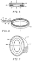
- capacitor 34 is illustrated.
- the embodiment illustrated utilizes conventional aluminum electrolytic capacitor technology in a novel orientation and configuration.
- An aluminum electrolytic capacitor can accumulate an electric charge between facing aluminum plates where a dielectric film is formed on the anode plate by anodic oxidation in the presence of a non-aqueous electrolyte.
- Capacitor 34 includes as principal components a first paper separator layer 42, an aluminum foil cathode plate layer 44, a second paper separator layer 46, and an aluminum foil anode plate layer 48.
- Lead wire terminals 50 and 52 are mechanically and electrically connected to cathode plate 44 and anode plate 48 respectively.
- the aforementioned layers 42, 44, 46 and 48 are wound together spirally about an axis parallel to the thickness direction T-T to form overlapping turns, thereby building up a cylindrical capacitor from the inside out.
- the embodiment illustrated in FIG. 6 is wound about a mandrel or tubular core so as to leave a central opening and to form a cylindrical capacitor of generally annular configuration.
- the term "cylindrical” is meant to be understood in its geometric sense, i.e., a surface traced by a straight line moving parallel to a fixed straight line and intersecting a fixed curve.
- the curve can be circular, as in the usual case, or it can be elliptical or oval, or arbitrarily shaped.
- one could form an annular capacitor by winding the plates and separators spirally about a mandrel or tubular core of circular, elliptical, oval, polygonal or other desired cross-section.
- the separator paper layers 42, 46 of capacitor 34 are saturated with a known electrolyte as is conventional in the construction of electrolytic capacitors, and thus it is necessary to provide a sealing layer or envelope about the exposed surfaces of the spirally wound capacitor, with the lead wire terminals 50 and 52 extending through the sealing layer to provide electrical access to the anode and cathode plate layers.
- a sealing layer or envelope about the exposed surfaces of the spirally wound capacitor, with the lead wire terminals 50 and 52 extending through the sealing layer to provide electrical access to the anode and cathode plate layers.
- Any suitable polymeric material that is resistant to the electrolyte can be utilized as the sealing layer, and an appropriate adhesive can be used to seal the points where the lead wire terminals pass through the sealing layer.
- a capacitor constructed in accordance with the present invention using conventional aluminum electrolytic capacitor technology is calculated to have the following construction details: Capacitance: 250 ⁇ F DC working voltage: 375 V Shape: Elliptical annulus Length: 8.3 cm Width: 7.3 cm Thickness: 6.5 mm Center opening: 6.7 cm x 5.7 cm Anode foil thickness: 105 ⁇ m Cathode foil thickness: 20 ⁇ m Paper separator thickness: 20 ⁇ m
- FIGS. 4 and 5 it can be appreciated how the present invention results in very efficient packaging of the large components of an implantable defibrillator.
- the layer comprised of capacitor 34 and batteries 38 and 40 there is very little wasted space because of the concentric arrangement of an elliptical battery (in two parts) and the elliptical annular capacitor.
- the layer comprised of circuit board 28 and header 14 there is likewise little wasted space because circuit board 28 and header 14 can be designed to selected shapes occupying selected areas of the plane as may be dictated by a well designed arrangement of the small components mounted on each.
- the efficient packaging arrangement derives in large part from the provision of a "flat" storage capacitor.
- flat it is meant that the thickness of the capacitor is less than either the width or the length of the capacitor, where thickness is measured along the axis about which the plates are spirally arranged.
- defibrillator 10' includes two concentric elliptical annular capacitors 34A' and 34B'. Separate concentric annular capacitors 34A' and 34B' are connected in series. This permits each capacitor to be constructed to withstand a voltage that is approximately half the total voltage that must be withstood by the entire capacitor bank, thereby easing the design requirements and enhancing reliability of the capacitors.
- capacitor technology such as polyethylene or polystyrene film capacitors, for example, wherein flexible anode plates, cathode plates and dielectric layers are wound together in a spiral. It also may be desirable to provide multiple capacitors connected in parallel to increase the total capacitance. Furthermore, the batteries need not be surrounded by the capacitor, as some other major component such as the circuit board may be more advantageously placed within the hollow center of the annular capacitor in a particular defibrillator design. Also, one may desire to provide a multiplicity of smaller capacitors without hollow centers that are arranged side by side in the same "flat” orientation described herein. A plurality of small "flat" hexagonally shaped capacitors could be densely packed together in honey-comb fashion and yet conform well to a curved peripheral edge of a defibrillator housing.
Landscapes
- Health & Medical Sciences (AREA)
- Cardiology (AREA)
- Heart & Thoracic Surgery (AREA)
- Engineering & Computer Science (AREA)
- Biomedical Technology (AREA)
- Nuclear Medicine, Radiotherapy & Molecular Imaging (AREA)
- Radiology & Medical Imaging (AREA)
- Life Sciences & Earth Sciences (AREA)
- Animal Behavior & Ethology (AREA)
- General Health & Medical Sciences (AREA)
- Public Health (AREA)
- Veterinary Medicine (AREA)
- Electrotherapy Devices (AREA)
Claims (10)
- Ein implantierbarer Herzschrittmacher (10), der einen elektrischen Kontakt (16), eine Batterie (38, 40), einen Energiespeicherkondensator (34) und eine Steuerschaltung (28) einschließt, die elektrisch mit dem genannten Kontakt, der Batterie und dem Kondensator verbunden ist, wobei die genannte Batterie, der Kondensator und die Steuerschaltung innerhalb eines Gehäuses (12) angeordnet sind, das eine gegenseitig orthogonal angeordnete Dicken- (T), Weiten- (W) und Längsachse (L) aufweist, wobei das genannte Gehäuse eine Dickenabmessung (t), die entlang der genannten Dickenachse (T) gemessen ist, eine Weitenabmessung (w), die entlang der genannten Weitenachse (W) gemessen ist und eine Längenabmessung (l), die entlang der genannten Längsachse (L) gemessen ist, wobei die genannte Dickenabmessung kleiner als jede der beiden genannten Weiten- und Längenabmessung ist;der genannte Energiespeicherkondensator weist eine gegenseitig orthogonale Dicken-, Weiten- und Längsachse auf und hat eine Dickenabmessung, die entlang der genannten Dickenachse gemessen ist, eine Weitenabmessung, die entlang der genannten Weitenachse gemessen ist, und eine Längenabmessung, die entlang der genannten Längsachse gemessen ist, wobei die genannte Dickenabmessung des genannten Kondensators kleiner als eine der genannten Weiten- und Längenabmessung des genannten Kondensators ist, und die genannte Dickenachse des genannten Kondensators parallel zu der genannten Dickenachse (T) des genannten Gehäuses ist;der genannte Kondensator enthält des weiteren eine erste Belagschicht (44), eine zweite Belagschicht (48) und eine dielektrische Schicht (46), die die genannte erste Belagschicht und die genannte zweite Belagschicht trennt;dadurch gekennzeichnet, daß die genannte erste Belag-, die zweite Belag- und die dielektrische Schicht spiralförmig angeordnet sind, um überlappende Windungen um eine Achse parallel zu der genannten Dickenachse des genannten Kondensators zu bilden.
- Der implantierbare Herzschrittmacher des Anspruchs 1, wobei die genannte erste Belag-, die zweite Belag- und die dielektrische Schicht allgemein als ein Ring angeordnet sind, der eine offene Mitte aufweist.
- Der implantierbare Herzschrittmacher des Anspruchs 2, wobei die genannte Batterie wenigstens teilweise innerhalb der genannten offenen Mitte des genannten Rings des genannten Kondensators angeordnet ist.
- Der implantierbare Herzschrittmacher des Anspruchs 2, wobei die genannte Steuerschaltung wenigstens teilweise innerhalb der genannten offenen Mitte des genannten Rings des genannten Kondensators angeordnet ist.
- Der implantierbare Herzschrittmacher des Anspruchs 2, wobei der genannte Ring allgemein elliptisch ist.
- Der implantierbare Herzschrittmacher des Anspruchs 5, wobei die genannte Batterie allgemein elliptisch ist und wenigstens teilweise innerhalb der genannten offenen Mitte des genannten Rings des genannten Kondensators angeordnet ist.
- Der implantierbare Herzschrittmacher des Anspruchs 3, wobei der genannte Kondensator und die genannte Batterie in einer ersten, gemeinsamen Ebene angeordnet sind, und wenigstens ein Teil der genannten Steuerschaltung auf einer Schaltungskarte angeordnet ist, die in einer zweite Ebene, im wesentlichen parallel zu der Ebene der ersten Ebene angeordnet ist.
- Der implantierbare Herzschrittmacher des Anspruchs 2, und der des weiteren einen zweiten Energiespeicherkondensator einschließt, der innerhalb des genannten Gehäuses angeordnet ist und wenigstens teilweise in der genannten offenen Mitte des genannten Rings des genannten Kondensators angeordnet ist.
- Der implantierbare Herzschrittmacher des Anspruchs 8, wobei der genannte zweite Energiespeicherkondensator selbst als ein Ring konstruiert ist, der eine offene Mitte hat.
- Der implantierbare Herzschrittmacher des Anspruchs 9, wobei die genannte Batterie wenigstens teilweise in der genannten offenen Mitte des genannten Rings des genannten zweiten Speicherkondensators angeordnet ist.
Applications Claiming Priority (3)
| Application Number | Priority Date | Filing Date | Title |
|---|---|---|---|
| US105836 | 1987-10-08 | ||
| US08/105,836 US5370663A (en) | 1993-08-12 | 1993-08-12 | Implantable cardiac-stimulator with flat capacitor |
| PCT/US1994/008977 WO1995005663A1 (en) | 1993-08-12 | 1994-08-09 | Implantable cardiac stimulator with flat capacitor |
Publications (2)
| Publication Number | Publication Date |
|---|---|
| EP0724466A1 EP0724466A1 (de) | 1996-08-07 |
| EP0724466B1 true EP0724466B1 (de) | 1998-05-27 |
Family
ID=22308047
Family Applications (1)
| Application Number | Title | Priority Date | Filing Date |
|---|---|---|---|
| EP94925220A Expired - Lifetime EP0724466B1 (de) | 1993-08-12 | 1994-08-09 | Implantierbarer herzschrittmacher mit einem flachen kondensator |
Country Status (5)
| Country | Link |
|---|---|
| US (1) | US5370663A (de) |
| EP (1) | EP0724466B1 (de) |
| DE (1) | DE69410627T2 (de) |
| ES (1) | ES2116613T3 (de) |
| WO (1) | WO1995005663A1 (de) |
Families Citing this family (60)
| Publication number | Priority date | Publication date | Assignee | Title |
|---|---|---|---|---|
| US5626626A (en) * | 1995-05-17 | 1997-05-06 | Ventritex, Inc. | Implantable medical apparatus with magnifying header |
| US5776072A (en) * | 1995-12-28 | 1998-07-07 | Cardiac Pacemakers, Inc. | Discrimination of atrial and ventricular signals from a single cardiac lead |
| DE69734599T2 (de) * | 1996-07-11 | 2007-02-08 | Medtronic, Inc., Minneapolis | Minimalinvasive implantierbare vorrichtung zur überwachung physiologischer vorgänge |
| US5749911A (en) * | 1997-01-24 | 1998-05-12 | Cardiac Pacemakers, Inc. | Implantable tissue stimulator incorporating deposited multilayer capacitor |
| US6745073B1 (en) | 1997-05-14 | 2004-06-01 | Pacesetter, Inc. | System and method of generating a low-pain multi-step defibrillation waveform for use in an implantable cardioverter/defibrillator (ICD) |
| US6484056B2 (en) * | 1997-05-14 | 2002-11-19 | Pacesetter, Inc. | System and method of generating a high efficiency biphasic defibrillation waveform for use in an implantable cardioverter/defibrillator (ICD) |
| US6233483B1 (en) * | 1997-05-14 | 2001-05-15 | Pacesetter, Inc. | System and method for generating a high efficiency biphasic defibrillation waveform for use in an implantable cardioverter/defibrillator (ICD). |
| US6152954A (en) | 1998-07-22 | 2000-11-28 | Cardiac Pacemakers, Inc. | Single pass lead having retractable, actively attached electrode for pacing and sensing |
| US6388866B1 (en) | 1998-04-03 | 2002-05-14 | Medtronic, Inc. | Implantable medical device having flat electrolytic capacitor with tailored anode layers |
| US6118652A (en) * | 1998-04-03 | 2000-09-12 | Medtronic, Inc. | Implantable medical device having flat electrolytic capacitor with laser welded cover |
| US6006133A (en) * | 1998-04-03 | 1999-12-21 | Medtronic, Inc. | Implantable medical device having flat electrolytic capacitor with consolidated electrode assembly |
| US6099600A (en) * | 1998-04-03 | 2000-08-08 | Medtronic, Inc. | Method of making a vacuum-treated liquid electrolyte-filled flat electrolytic capacitor |
| US6477037B1 (en) | 1998-04-03 | 2002-11-05 | Medtronic, Inc. | Implantable medical device having flat electrolytic capacitor with miniaturized epoxy connector droplet |
| US6157531A (en) * | 1998-04-03 | 2000-12-05 | Medtronic, Inc. | Implantable medical device having flat electrolytic capacitor with liquid electrolyte fill tube |
| US6009348A (en) * | 1998-04-03 | 1999-12-28 | Medtronic, Inc. | Implantable medical device having flat electrolytic capacitor with registered electrode layers |
| US6402793B1 (en) | 1998-04-03 | 2002-06-11 | Medtronic, Inc. | Implantable medical device having flat electrolytic capacitor with cathode/case electrical connections |
| US6445948B1 (en) | 1998-04-03 | 2002-09-03 | Medtronic, Inc. | Implantable medical device having a substantially flat battery |
| US6141205A (en) * | 1998-04-03 | 2000-10-31 | Medtronic, Inc. | Implantable medical device having flat electrolytic capacitor with consolidated electrode tabs and corresponding feedthroughs |
| US6032075A (en) * | 1998-04-03 | 2000-02-29 | Medtronic, Inc. | Implantable medical device with flat aluminum electolytic capacitor |
| US6042624A (en) * | 1998-04-03 | 2000-03-28 | Medtronic, Inc. | Method of making an implantable medical device having a flat electrolytic capacitor |
| US6493212B1 (en) | 1998-04-03 | 2002-12-10 | Medtronic, Inc. | Implantable medical device having flat electrolytic capacitor with porous gas vent within electrolyte fill tube |
| US6249423B1 (en) * | 1998-04-21 | 2001-06-19 | Cardiac Pacemakers, Inc. | Electrolytic capacitor and multi-anodic attachment |
| US6187028B1 (en) | 1998-04-23 | 2001-02-13 | Intermedics Inc. | Capacitors having metallized film with tapered thickness |
| US6110233A (en) * | 1998-05-11 | 2000-08-29 | Cardiac Pacemakers, Inc. | Wound multi-anode electrolytic capacitor with offset anodes |
| US6459566B1 (en) | 1998-06-24 | 2002-10-01 | Medtronic, Inc. | Implantable medical device having flat electrolytic capacitor with laser welded cover |
| US6501990B1 (en) | 1999-12-23 | 2002-12-31 | Cardiac Pacemakers, Inc. | Extendable and retractable lead having a snap-fit terminal connector |
| US6463334B1 (en) | 1998-11-02 | 2002-10-08 | Cardiac Pacemakers, Inc. | Extendable and retractable lead |
| US6191931B1 (en) * | 1998-08-28 | 2001-02-20 | Pacesetter, Inc. | Aluminum electrolytic capacitor with conductive feed-through for implantable medical device |
| US6275729B1 (en) * | 1998-10-02 | 2001-08-14 | Cardiac Pacemakers, Inc. | Smaller electrolytic capacitors for implantable defibrillators |
| US6556863B1 (en) * | 1998-10-02 | 2003-04-29 | Cardiac Pacemakers, Inc. | High-energy capacitors for implantable defibrillators |
| US6094597A (en) * | 1999-02-05 | 2000-07-25 | Medtronic, Inc. | Implantable medical device incorporating distributed core, step-up transformer |
| US6297943B1 (en) * | 1999-03-19 | 2001-10-02 | Pacesetter, Inc. | Capacitor with thermosealed polymeric case for implantable medical device |
| US6678559B1 (en) | 1999-03-23 | 2004-01-13 | Medtronic, Inc. | Implantable medical device having a capacitor assembly with liner |
| US6192277B1 (en) | 1999-07-06 | 2001-02-20 | Pacesetter, Inc. | Implantable device with bevel gear actuation for lead retention and actuation |
| US6385490B1 (en) | 1999-12-16 | 2002-05-07 | Cardiac Pacemakers, Inc. | Capacitors with recessed rivets allow smaller implantable defibrillators |
| US6426864B1 (en) | 2000-06-29 | 2002-07-30 | Cardiac Pacemakers, Inc. | High energy capacitors for implantable defibrillators |
| US6509588B1 (en) | 2000-11-03 | 2003-01-21 | Cardiac Pacemakers, Inc. | Method for interconnecting anodes and cathodes in a flat capacitor |
| US6699265B1 (en) | 2000-11-03 | 2004-03-02 | Cardiac Pacemakers, Inc. | Flat capacitor for an implantable medical device |
| US6687118B1 (en) | 2000-11-03 | 2004-02-03 | Cardiac Pacemakers, Inc. | Flat capacitor having staked foils and edge-connected connection members |
| US9192522B2 (en) | 2003-05-02 | 2015-11-24 | Eveready Battery Company, Inc. | Tampon assembly having shaped pledget |
| US7966070B2 (en) * | 2003-09-12 | 2011-06-21 | Medtronic, Inc. | Feedthrough apparatus with noble metal-coated leads |
| US20070260282A1 (en) * | 2003-09-12 | 2007-11-08 | Taylor William J | Feedthrough apparatus with noble metal-coated leads |
| US20050154423A1 (en) * | 2004-01-13 | 2005-07-14 | Goedeke Steven D. | Method for reducing implantable defibrillator volume |
| US7283867B2 (en) * | 2004-06-10 | 2007-10-16 | Ndi Medical, Llc | Implantable system and methods for acquisition and processing of electrical signals from muscles and/or nerves and/or central nervous system tissue |
| US7426104B2 (en) * | 2004-07-16 | 2008-09-16 | Cardiac Pacemakers, Inc. | Method and apparatus for insulative film for capacitor components |
| US7075777B2 (en) * | 2004-07-16 | 2006-07-11 | Cardiac Pacemakers, Inc. | Method and apparatus for a capacitor shell including two mateable cupped components |
| US7531010B1 (en) | 2005-01-07 | 2009-05-12 | Pacesetter, Inc. | Design for capacitor anode assembly |
| US7196899B1 (en) | 2005-01-07 | 2007-03-27 | Pacesetter, Inc. | Capacitor anode assembly |
| US20060206151A1 (en) * | 2005-02-16 | 2006-09-14 | Fei Lu | Heart rhythm management system |
| US20060247714A1 (en) * | 2005-04-28 | 2006-11-02 | Taylor William J | Glass-to-metal feedthrough seals having improved durability particularly under AC or DC bias |
| US20060247715A1 (en) * | 2005-04-29 | 2006-11-02 | Youker Nick A | Method and apparatus for an implantable pulse generator with a stacked battery and capacitor |
| US7355840B2 (en) * | 2005-05-09 | 2008-04-08 | Cardiac Pacemakers, Inc. | Method and apparatus for a capacitor shell including two mateable cupped components |
| US7340305B2 (en) * | 2005-06-09 | 2008-03-04 | Cardiac Pacemakers, Inc. | Implantable medical device feedthrough assembly having a coated conductor |
| US7385802B1 (en) | 2005-10-05 | 2008-06-10 | Pacesetter Inc. | Electrolytic capacitor |
| US20070247786A1 (en) * | 2006-04-24 | 2007-10-25 | Aamodt Paul B | Torroidal battery for use in implantable medical device |
| US7404829B1 (en) | 2006-06-12 | 2008-07-29 | Pacesetter, Inc. | Electrode-separator combination for improved assembly of layered electrolytic capacitors |
| EP2032108A4 (de) | 2006-06-12 | 2011-01-19 | Playtex Products Inc | Tamponanordnung mit passender positionierung eines wattebausches im körper |
| US8874214B2 (en) * | 2006-08-28 | 2014-10-28 | Cardiac Pacemakers, Inc. | Implantable pulse generator with a stacked capacitor, battery, and electronics |
| US11862395B2 (en) * | 2021-11-30 | 2024-01-02 | Nissan North America, Inc. | Energy bank including integrated supercapacitor-battery structures |
| US11817260B2 (en) | 2021-11-30 | 2023-11-14 | Nissan North America, Inc. | Integrated supercapacitor-battery structure |
Family Cites Families (8)
| Publication number | Priority date | Publication date | Assignee | Title |
|---|---|---|---|---|
| US965992A (en) * | 1909-01-28 | 1910-08-02 | Dean Electric Co | Electrical condenser. |
| US3622847A (en) * | 1969-11-10 | 1971-11-23 | Gen Electric | Flag tap retention means in capacitors |
| US3987799A (en) * | 1973-07-12 | 1976-10-26 | Coratomic Inc. | Heart pacer |
| US4254755A (en) * | 1979-02-28 | 1981-03-10 | Morgan Steven R | Ball throwing machine useful in practicing the game of volleyball |
| JPS5860517A (ja) * | 1981-10-06 | 1983-04-11 | 富士通株式会社 | 巻回形コンデンサの電極用金属箔 |
| US4546415A (en) * | 1981-12-10 | 1985-10-08 | North American Philips Corporation | Heat dissipation aluminum electrolytic capacitor |
| US5131388A (en) * | 1991-03-14 | 1992-07-21 | Ventritex, Inc. | Implantable cardiac defibrillator with improved capacitors |
| US5241960A (en) * | 1992-07-08 | 1993-09-07 | Angeion Corporation | Defibrillator pulse generator |
-
1993
- 1993-08-12 US US08/105,836 patent/US5370663A/en not_active Expired - Lifetime
-
1994
- 1994-08-09 ES ES94925220T patent/ES2116613T3/es not_active Expired - Lifetime
- 1994-08-09 DE DE69410627T patent/DE69410627T2/de not_active Expired - Fee Related
- 1994-08-09 WO PCT/US1994/008977 patent/WO1995005663A1/en not_active Ceased
- 1994-08-09 EP EP94925220A patent/EP0724466B1/de not_active Expired - Lifetime
Also Published As
| Publication number | Publication date |
|---|---|
| EP0724466A1 (de) | 1996-08-07 |
| US5370663A (en) | 1994-12-06 |
| WO1995005663A8 (en) | 2001-06-07 |
| DE69410627T2 (de) | 1998-12-03 |
| DE69410627D1 (de) | 1998-07-02 |
| WO1995005663A1 (en) | 1995-02-23 |
| ES2116613T3 (es) | 1998-07-16 |
Similar Documents
| Publication | Publication Date | Title |
|---|---|---|
| US5370663A (en) | Implantable cardiac-stimulator with flat capacitor | |
| EP2239801B1 (de) | Flache Batteriezellen und Herstellungsverfahren | |
| US6799072B2 (en) | Electrically insulated component sub-assemblies of implantable medical devices | |
| US8086312B2 (en) | Capacitors for medical devices | |
| US6678559B1 (en) | Implantable medical device having a capacitor assembly with liner | |
| EP2783407B1 (de) | Elektrochemische zelle mit aneinander angrenzenden kathoden | |
| US10661089B2 (en) | Electrochemical cell with adjacent cathodes | |
| CA2061344C (en) | Implantable cardiac defibrillator with improved capacitors | |
| US6674634B2 (en) | Implantable heart monitors having flat capacitors with curved profiles | |
| US6650942B2 (en) | Implantable medical device with dual cell power source | |
| US5439482A (en) | Prophylactic implantable cardioverter-defibrillator | |
| EP1406692A2 (de) | Implantierbare medizinische vorrichtung mit einer doppelzellen-batterie | |
| US20070254212A1 (en) | Battery assembly for use in implantable medical device | |
| EP1611630A1 (de) | Implantierbare hochleistungsbatterie mit verbesserter sicherheit und verfahren zu deren herstellung | |
| US20050154423A1 (en) | Method for reducing implantable defibrillator volume | |
| US11705287B2 (en) | Sintered electrodes for a capacitor |
Legal Events
| Date | Code | Title | Description |
|---|---|---|---|
| PUAI | Public reference made under article 153(3) epc to a published international application that has entered the european phase |
Free format text: ORIGINAL CODE: 0009012 |
|
| 17P | Request for examination filed |
Effective date: 19960118 |
|
| AK | Designated contracting states |
Kind code of ref document: A1 Designated state(s): DE ES FR GB IT NL SE |
|
| GRAG | Despatch of communication of intention to grant |
Free format text: ORIGINAL CODE: EPIDOS AGRA |
|
| 17Q | First examination report despatched |
Effective date: 19971003 |
|
| GRAG | Despatch of communication of intention to grant |
Free format text: ORIGINAL CODE: EPIDOS AGRA |
|
| GRAH | Despatch of communication of intention to grant a patent |
Free format text: ORIGINAL CODE: EPIDOS IGRA |
|
| RAP1 | Party data changed (applicant data changed or rights of an application transferred) |
Owner name: SULZER INTERMEDICS INC. |
|
| GRAH | Despatch of communication of intention to grant a patent |
Free format text: ORIGINAL CODE: EPIDOS IGRA |
|
| GRAA | (expected) grant |
Free format text: ORIGINAL CODE: 0009210 |
|
| ITF | It: translation for a ep patent filed | ||
| AK | Designated contracting states |
Kind code of ref document: B1 Designated state(s): DE ES FR GB IT NL SE |
|
| REF | Corresponds to: |
Ref document number: 69410627 Country of ref document: DE Date of ref document: 19980702 |
|
| REG | Reference to a national code |
Ref country code: ES Ref legal event code: FG2A Ref document number: 2116613 Country of ref document: ES Kind code of ref document: T3 |
|
| ET | Fr: translation filed | ||
| PLBE | No opposition filed within time limit |
Free format text: ORIGINAL CODE: 0009261 |
|
| STAA | Information on the status of an ep patent application or granted ep patent |
Free format text: STATUS: NO OPPOSITION FILED WITHIN TIME LIMIT |
|
| 26N | No opposition filed | ||
| PGFP | Annual fee paid to national office [announced via postgrant information from national office to epo] |
Ref country code: FR Payment date: 20000719 Year of fee payment: 7 |
|
| PGFP | Annual fee paid to national office [announced via postgrant information from national office to epo] |
Ref country code: SE Payment date: 20000720 Year of fee payment: 7 Ref country code: GB Payment date: 20000720 Year of fee payment: 7 Ref country code: DE Payment date: 20000720 Year of fee payment: 7 |
|
| PGFP | Annual fee paid to national office [announced via postgrant information from national office to epo] |
Ref country code: NL Payment date: 20000724 Year of fee payment: 7 |
|
| PGFP | Annual fee paid to national office [announced via postgrant information from national office to epo] |
Ref country code: ES Payment date: 20000908 Year of fee payment: 7 |
|
| PG25 | Lapsed in a contracting state [announced via postgrant information from national office to epo] |
Ref country code: GB Free format text: LAPSE BECAUSE OF NON-PAYMENT OF DUE FEES Effective date: 20010809 |
|
| PG25 | Lapsed in a contracting state [announced via postgrant information from national office to epo] |
Ref country code: SE Free format text: LAPSE BECAUSE OF NON-PAYMENT OF DUE FEES Effective date: 20010810 Ref country code: ES Free format text: LAPSE BECAUSE OF NON-PAYMENT OF DUE FEES Effective date: 20010810 |
|
| PG25 | Lapsed in a contracting state [announced via postgrant information from national office to epo] |
Ref country code: NL Free format text: LAPSE BECAUSE OF NON-PAYMENT OF DUE FEES Effective date: 20020301 |
|
| EUG | Se: european patent has lapsed |
Ref document number: 94925220.9 |
|
| GBPC | Gb: european patent ceased through non-payment of renewal fee |
Effective date: 20010809 |
|
| PG25 | Lapsed in a contracting state [announced via postgrant information from national office to epo] |
Ref country code: FR Free format text: LAPSE BECAUSE OF NON-PAYMENT OF DUE FEES Effective date: 20020430 |
|
| NLV4 | Nl: lapsed or anulled due to non-payment of the annual fee |
Effective date: 20020301 |
|
| PG25 | Lapsed in a contracting state [announced via postgrant information from national office to epo] |
Ref country code: DE Free format text: LAPSE BECAUSE OF NON-PAYMENT OF DUE FEES Effective date: 20020501 |
|
| REG | Reference to a national code |
Ref country code: FR Ref legal event code: ST |
|
| REG | Reference to a national code |
Ref country code: ES Ref legal event code: FD2A Effective date: 20020911 |
|
| PG25 | Lapsed in a contracting state [announced via postgrant information from national office to epo] |
Ref country code: IT Free format text: LAPSE BECAUSE OF NON-PAYMENT OF DUE FEES;WARNING: LAPSES OF ITALIAN PATENTS WITH EFFECTIVE DATE BEFORE 2007 MAY HAVE OCCURRED AT ANY TIME BEFORE 2007. THE CORRECT EFFECTIVE DATE MAY BE DIFFERENT FROM THE ONE RECORDED. Effective date: 20050809 |