EP0724159A1 - Analytical tachometers - Google Patents
Analytical tachometers Download PDFInfo
- Publication number
- EP0724159A1 EP0724159A1 EP96300484A EP96300484A EP0724159A1 EP 0724159 A1 EP0724159 A1 EP 0724159A1 EP 96300484 A EP96300484 A EP 96300484A EP 96300484 A EP96300484 A EP 96300484A EP 0724159 A1 EP0724159 A1 EP 0724159A1
- Authority
- EP
- European Patent Office
- Prior art keywords
- signal
- analysis
- engine
- sensor means
- vibration
- Prior art date
- Legal status (The legal status is an assumption and is not a legal conclusion. Google has not performed a legal analysis and makes no representation as to the accuracy of the status listed.)
- Granted
Links
Images



Classifications
-
- G—PHYSICS
- G01—MEASURING; TESTING
- G01H—MEASUREMENT OF MECHANICAL VIBRATIONS OR ULTRASONIC, SONIC OR INFRASONIC WAVES
- G01H1/00—Measuring characteristics of vibrations in solids by using direct conduction to the detector
-
- G—PHYSICS
- G01—MEASURING; TESTING
- G01M—TESTING STATIC OR DYNAMIC BALANCE OF MACHINES OR STRUCTURES; TESTING OF STRUCTURES OR APPARATUS, NOT OTHERWISE PROVIDED FOR
- G01M15/00—Testing of engines
- G01M15/04—Testing internal-combustion engines
- G01M15/10—Testing internal-combustion engines by monitoring exhaust gases or combustion flame
- G01M15/102—Testing internal-combustion engines by monitoring exhaust gases or combustion flame by monitoring exhaust gases
- G01M15/106—Testing internal-combustion engines by monitoring exhaust gases or combustion flame by monitoring exhaust gases using pressure sensors
-
- G—PHYSICS
- G01—MEASURING; TESTING
- G01M—TESTING STATIC OR DYNAMIC BALANCE OF MACHINES OR STRUCTURES; TESTING OF STRUCTURES OR APPARATUS, NOT OTHERWISE PROVIDED FOR
- G01M15/00—Testing of engines
- G01M15/04—Testing internal-combustion engines
- G01M15/12—Testing internal-combustion engines by monitoring vibrations
-
- G—PHYSICS
- G01—MEASURING; TESTING
- G01P—MEASURING LINEAR OR ANGULAR SPEED, ACCELERATION, DECELERATION, OR SHOCK; INDICATING PRESENCE, ABSENCE, OR DIRECTION, OF MOVEMENT
- G01P3/00—Measuring linear or angular speed; Measuring differences of linear or angular speeds
- G01P3/42—Devices characterised by the use of electric or magnetic means
- G01P3/44—Devices characterised by the use of electric or magnetic means for measuring angular speed
- G01P3/48—Devices characterised by the use of electric or magnetic means for measuring angular speed by measuring frequency of generated current or voltage
-
- F—MECHANICAL ENGINEERING; LIGHTING; HEATING; WEAPONS; BLASTING
- F02—COMBUSTION ENGINES; HOT-GAS OR COMBUSTION-PRODUCT ENGINE PLANTS
- F02B—INTERNAL-COMBUSTION PISTON ENGINES; COMBUSTION ENGINES IN GENERAL
- F02B1/00—Engines characterised by fuel-air mixture compression
- F02B1/02—Engines characterised by fuel-air mixture compression with positive ignition
- F02B1/04—Engines characterised by fuel-air mixture compression with positive ignition with fuel-air mixture admission into cylinder
Definitions
- the present invention relates to tachometers suitable for use in maintenance work on automotive engines and like applications.
- the tachometers described below include features enabling analytical work to be carried out in relation to such engines, such as diagnosis of misfiring faults and the like.
- the tachometers to which the invention relates are intended essentially for analytical work, such as in engine maintenance and diagnosis, and it is not presently anticipated that such tachometers would find application by way of permanent installation in any one given vehicle for the indication of engine speed.
- a tachometer For analytical use and indeed other uses, a tachometer needs to be able to measure and indicate actual engine rotational speed over at least a continuous range of engine speeds from, for example, 1000 to 3000 RPM at a minimum, and preferably the tachometer should cover a significantly wider range of speeds than this, such as 700 to 5000 rpm to a resolution of around 30 rpm. Obviously, in respect of the speed range covered, it is essential that continuous coverage be provided and not an ability to determine engine speeds at particular locations within a given speed range.
- an object of the present invention is to provide tachometer apparatus and a corresponding method, particularly applicable to automotive engine analysis applications, offering continuous coverage of at least the minimum band of engine speeds covered by conventional tachometer apparatus, and offering an ability to provide these functions in relation to a wide range of engines by means of a simple connection technique not requiring particular electrical or the like connections to the engine, whereby wide coverage of varying engine types is available.
- tachometer apparatus and a corresponding method particularly applicable to automotive engine analysis applications, offering continuous coverage of at least the minimum band of engine speeds covered by conventional tachometer apparatus, and offering an ability to provide these functions in relation to a wide range of engines by means of a simple connection technique not requiring particular electrical or the like connections to the engine, whereby wide coverage of varying engine types is available.
- advantages of low cost, ease of attachment and low power consumption allowing battery operation and portability.
- the apparatus comprises vibration sensing means adapted for connection directly to an engine or the like to be analysed, or to structure connected thereto.
- the vibration sensing means is adapted to generate signals representative of vibrational characteristics of the operating engine.
- the vibration sensing means produces vibrational signals having characteristics comprising a vibrational signal signature or pattern of a given engine under test.
- the apparatus is adapted to analyse the vibrational signal signature by reference to a known vibrational signature corresponding thereto, whereby engine speed is determined.
- the Hicho specification discloses a vibration transducer mounted to a rotating machine for sensing vibration thereof. An output electrical signal from the transducer is analysed to generate a display of vibrational displacement per unit time, together with a speed display indicative of rotational speed, and a bearing condition display indicative of bearing condition.
- This apparatus is not tachometer apparatus capable of indicating rotational speed over a continuous range of engine speeds, even of the narrowest proportions.
- the Hicho apparatus is a vibration analyser adapted to enable monitoring of defects in rotating machines and which incidentally is able to indicate rotational speed at the standard rotational speed settings at which such vibrational analysis are conventionally carried out.
- Such speed analysis is effected by speed analysis means wherein random or sporadic noise is eliminated, and components of the frequency not related to the rotating speed of the machine are eliminated to obtain an accurate estimation of the machine's running speed.
- speed analysis means wherein random or sporadic noise is eliminated, and components of the frequency not related to the rotating speed of the machine are eliminated to obtain an accurate estimation of the machine's running speed.
- harmonic signature or pattern identification means based upon previous analysis of the vibrational signature of the same or a similar engine configuration enables the characteristic harmonic elements of the signature to be recognised amongst the plethora of additional vibrational peaks, and enables also such identification to be effected throughout a continuous range of engine rotational speeds, and hence the continuous operational characteristics of a tachometer can be obtained.
- the embodiments of the present invention enable not only the extraction from a complex vibrational pattern of rotational speed, across a range of such speeds, but also there is enabled the identification of anomalies in the vibrational pattern which provide a valuable diagnostic and analytical function additional to that relating to rotational speed, including recognition of patterns due to misfiring and other combustion-related abnormalities.
- a direct corollary to the mode of operation of the tachometer apparatus of the invention based as it is upon the recognition of the vibrational harmonic signature of an engine over a range of engine speeds, is the recognition of a known engine vibrational signature from amongst a range of signature possibilities, whereby the engine type can be identified, in a case where such information is not available from the usual sources.
- a further technical feature of the apparatus of the present invention which is of technical significance with respect to the above-discussed state of the art concerns an inherent characteristic of the technique of vibrational signature recognition.
- This characteristic is the fact that such recognition avoids the need to eliminate significant parts of the vibrational output in order to detect rotational speed, and avoids the need to use integrator apparatus, as employed in the above-discussed Hicho reference.
- the avoidance of the use of an integrator has significance in relation to tachometer apparatus intended primarily for automotive engine use, due to the low amplitude of the vibrational signals available to be sensed. In many cases, the use of an integrator in vibration-based analysis of an automotive engine would lead to insufficient signals for tachometric purposes.
- the invention side-steps this difficulty and is able to offer apparatus having sufficient sensitivity for even the most well balanced engines available in the automotive field. It was originally believed that the sensed engine vibration was caused by inertia forces due to the reciprocation of the engine pistons. However, since a six cylinder engine is totally balanced to second order in its inertia forces and yet can still be seen to vibrate, it is apparent that the dominant source of vibration arises from torsional variations in the crankshaft as a result of the combustion process and the inherent reciprocating nature of the engine.
- the tachometer operates by spectrally analysing the sensor or accelerometer output signal, identifying a speed-related component in terms of the spectral "signature", and uses the instantaneous position of the relevant portion of the signature to determine the engine speed.
- the signature contains dominant peaks found to be situated at multiples of the engine's crankshaft revolution frequency, and these can be readily identified within the power spectral density across a wide range of engine speeds.
- the design philosophy with respect to the vibration sensor was firstly to minimise the electronics in the sensor head in order to limit physical size, and secondly to perform as much of the signal processing by software provision so as to maintain maximum control over the system performance.
- a further aspect of the invention relates to a diagnostic function arising from the ability of the software system forming part of the analysis function to anaylse the engine vibration signature, taking account of the known harmonic characteristics of the engine configuration in question. Accordingly, the software system can be readily adapted to identify the presence (if any) of additional peaks or the absence of expected peaks in the pattern or signature produced by the engine, such additional peaks corresponding to faults arising from a variety of possible causes, mostly combustion-related.
- a still further aspect of the invention relates to the arrangements for transmission of signals from the vibration sensor to the corresponding signal analysis apparatus and the general arrangements for processing of the signals whereby the use of the apparatus is rendered convenient and manageable in the confined location of an automotive engine bay.
- EP - B- 0 458 053 Bosch a motor vehicle test unit in which convenience of operation is provided by means of an arrangement in which the main body of the test apparatus is located in a substantial mobile base unit and this base unit is connected by a manoeuvrable boom arm to a sub-unit which includes control and display means enabling control of the test functions and display of measured values.
- the sub unit is connected to the automotive engine or other equipment under test by means of short conductor leads from the locally-positioned sub unit, whereby convenience of operation is provided.
- An object of this aspect of the present invention is to provide a method and apparatus for convenient sensing of mechanical or electrical or other operating parameters of an automotive or other power driven installation, without the inherent disadvantages of the conventional or known cable connection systems and base unit/boom/sub unit systems.
- apparatus 10 for rotary machine analysis and particularly adapted for engine analysis, whereby the analytical function is capable of providing tachometric data, comprises principal functions of a sensor head 12, a data capture system 14 and a software sub-system 16 including a display function 18.
- Data capture system 14 and software sub-system 16 constitute a single unit of the entire apparatus 10, namely a signal processing and display unit 20, which receives signals from sensor head 12 from a radio frequency wireless transmitter device 22 (forming part of sensor head 12).
- a corresponding radio frequency wireless transmission receiver device 24 is provided as part of data capture system 14 to receive the corresponding RF signals.
- This RF simplex data link, comprising the receiver/transmitter pair 22, 24 is licensed for use in both UK and elsewhere in Europe for the transmission of non-speech analogue signals.
- the band width of the receiver/transmitter pair allows connection to the signal processing and display unit 20 of up to 4 sensor heads 12 in multiple channels.
- Sensor head 12 comprises an accelerometer 30, an amplifier 32, and the above-mentioned RF transmitter 22.
- Data capture system 14 comprises firstly the above-mentioned RF transmission receiver device 24, together with a low pass filter 34, a sample and hold device 36, and an analogue-to-digital converter or ADC device 38.
- Software sub-system 16 comprises, in addition to display function 18 mentioned above, a power spectral density function 40 and a signature detect function 42.
- the method of the invention comprises using sensor head 12 to generate a signal related to sensed vibrations by installing the sensor head on engine block 28.
- the signal produced by sensor head 12 is analysed to determine the rate of rotation of engine 28. This is done by subjecting the signal from sensor head 12 to a method of tachometric analysis based on the vibration-generated signal.
- the analytical technique deals with the plurality of waveforms produced by the sensor head by recognising a pattern or signature having a harmonic content therein which is characteristic of the configuration of engine being analysed.
- the signal obtained from data capture system 14 is subjected to power spectral density processing by function 40 and the characteristic engine signature in the resulting plot is recognised by signature detect function 42, whereby the particular peak corresponding to engine speed can be identified by reference to the relevant harmonics and the engine speed therefore displayed by RPM display function 18.
- the typical in-use situation for the tachometric apparatus will be in an analytical function in relation to an engine block 28 of known configuration eg four cylinders in-line or six cylinders in V-configuration (V6), or V8 etc.
- the engine configuration may not be known and in such a situation the vibration data obtained may nevertheless be capable of analysis to determine not only the configuration itself (by recognition of the engine's signature) but also the engine speed in a subsequent step.
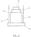
- Fig 2 Some details of the construction of the sensor head 12 are shown in Fig 2, namely an accelerometer 44, a thermally insulating mounting 46 for the accelerometer, a magnet 48, an insulation tube 50 and a combined amplifier/RF transmitter/antenna unit located on top of accelerometer 44. It will be understood that the combined unit 52 corresponds to the functions 32 and 22 identified in Fig 1.
- accelerometer 44 itself, this comprises two main elements, namely a mass which when subjected to an acceleration produces a force, and a Kynar piezo film transducer, to convert the force to an electric charge.
- the transducer is mounted on a ceramic substrate (not shown). This transducer construction was chosen for its wide frequency range from 5 hertz to 10 kilohertz, with a linear response characteristic (plus or minus one per cent).
- the construction of the accelerometer also lends itself to low cost production.
- Accelerometer 44 is firmly mounted on the short length of thermally insulating mounting 46 which is itself firmly bonded to a samarium cobalt magnet, of pull strength 15 kilograms, which allows attachment of the sensor head to engine blocks of almost all kinds, due to the usual availability of steel bolt heads even on alloy engines.
- Magnet 48 is of annular "pot type" construction.
- An insulating cylinder is likewise bonded to magnet 48 to isolate accelerometer 44 from electrical contact with (or indeed excessively close proximity to) other electrical systems in the engine compartment.
- accelerometer 44 comprises a piezoelectric film sensor and may have a buffered output.
- Other mechanical forms of accelerometer structure eg a mechanical diaphragm etc are also acceptable. It is important to choose a sensor having the appropriate level of sensitivity so as to produce the requisite amplitude or range of signals for analysis. In this regard, it is of significance that the vibrational signals available from some well-balanced automotive engines are of such low amplitude as to raise significant difficulties if known vibrational analysis equipment (as discussed above in relation to the prior art) were employed.
- amplifier/transmitter/antenna unit 52 the construction of this may be based upon a known receiver/transmitter pair, for example as used for the transmission of unmodulated RF signals for alarm activation purposes, and therefore circuit data is not provided herein.
- amplifier/transmitter/antenna unit 52 can be an adapted off-the-shelf radio link device of the alarm signal transmission kind incorporating a signal amplifier and further modified by the addition of modulation means whereby the RF signal is transmitted in amplitude or frequency- modulated form (preferably amplitude-modulated) so as to carry the vibrational signal data.
- sensor head 12 can operate as a self-contained battery-operated unit which mounts directly on engine block 28 by magnetic means 48 with a potentially relatively long self-powered life based on a relatively small battery supply. This enables the signal processing and display unit 20 to be located at any convenient position in the vicinity of sensor head 12, but without any electrical conductors therebetween.
- the RF receiver unit 24 complements the transmitter device 22 discussed above and is of corresponding construction, adapted to receive the modulated signal from transmitter 22 and to pass same to the low pass filter 34 and hence to sample and hold device 36 and thus onwards to the ADC unit 38.
- data capture system 14 takes the raw signal produced by sensor head 12 and converts its into digital form, and stores it in memory prior to digital signal processing.
- Low pass filter 34 is of significance in that it represents the only filter function needed by the apparatus 10.
- Filter 34 is an anti-aliasing filter.
- the anti-aliasing filter removes frequencies which would otherwise be changed by the sampling rate of the ADC unit. Otherwise however the system 10 is not dependent upon filter functions, and notably does not use these at all for the purposes of signal analysis and identification of tachometric data.
- Sample and hold function 36 stores the signal data in memory prior to digital signal processing.
- the ADC function comprises a 12 bit analogue-to-digital processor which allows the analogue data to be quantised into 4096 voltage steps.
- the data capture system runs in parallel with the signal processing software sub-systems 16, allowing the display function 18 to be updated twice a second.
- the RPM-tracking capability of the apparatus 10 in this embodiment can display up to 120 different numerical values for engine speed per minute, whereby relatively rapid response to changing engine speeds, as needed for modern engine-speed-dependent quantitative tests (such as emission analysis) is provided.
- Power spectral density function 40 subjects the quantised digital signal to a fast fourier transform routine in order to generate the power spectral density data therefrom, for analytical purposes.
- the power spectral density analysis function carried out in software sub-system 16 may use a well recognised algorithm (see eg "Numerical Recipes in C” published by Cambridge University Press).
- the plurality of superimposed waveforms present in the data input to software sub-systems 16 is indicated in the micro-plot 56 in Fig 1. This is shown as the output of amplifier unit 32, but is likewise representative of the input to the software sub-system 16.
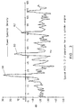
- Fig 3 shows the resultant power spectral density "PSD" data obtained for (in this case) a four cylinder engine.
- Fig 3 shows such a signature for a four cylinder engine including peaks 58, 60 and 62 corresponding to f (engine speed) and 2f and 3f respectively.
- Fig 4 shows an idealised signature for a V6 engine running at 1500 rpm with peaks identified at 64, 66 and 68.
- the signature detect function 42 which carries out a peak search routine using an algorithm selected in accordance with the engine type, which is known from data relating to engine block 28.
- signature detect function 42 subjects the power spectral density data, such as that shown in Fig 3 to an analysis routine corresponding to the engine configuration in question and enabling identification of the relevant peak (or a related peak) corresponding to the engine rpm frequency "f" for the engine in question.
- the peak in question for the 1-2-3 signature of a 4 cylinder engine is known to be peak 58 which is at a multiple of engine speed.
- peak 58 is at a multiple of engine speed.
- peaks 64, 66 and 68 are at 0.5 f and f and 2f, actual engine speed is given by peak 66.
- the micro-plot 70 indicates the "signature" which can be obtained from the relevant peaks in the power spectral density plot produced by PSD function 40, which signature is subjected to the analysis routine described herein and performed in signature detect function 42.
- the signature detect function 42 thus enables identification of the relevant key engine signature peak which provides the engine RPM for display unit 18, thus enabling display of the engine RPM by display unit 18.
- the apparatus 10 operates successfully on a wide range of both petrol and diesel four cylinder engines, for speeds ranging from tick over at 700 RPM to operation up to 5000 RPM. Illustrative results from test work are shown in the following tabulations.
- the engine RPM obtained by the apparatus 10 and displayed by display function 18 is shown in the lower horizontal column in each case.
- the upper horizontal column shows the engine speed set by an existing tachometric system (identified as "prior system").
- the numerical values given for the prior system should be interpreted as values at which the engine was held on a visual inspection basis to an accuracy of plus or minus 50 RPM.
- Table 1 shows the results for a four cylinder diesel engine, table 2 for a four cylinder petrol engine and table 3 for a six cylinder diesel engine. These tabulations were obtained with the sensor head 12 mounted on the engine using the magnetic attachment system described above. It was considered best to site the sensor head at the end of the engine furthest from the fly wheel/gear box assembly in order to minimise the vibration-damping and torque-smoothing effects of these.
- Diagnostic functions for the basically tachometric apparatus 10 have also been identified and tested.
- an additional peak 72 centrally between the peaks 64 and 66.
- Such an additional peak is produced by a cylinder misfire and has been found to be characteristic of such a combustion-related fault. Since, by selection of the appropriate algorithm for the signature detect analysis at function 42, it is already known what pattern of peaks to expect for a given engine, the location and identification of additional peaks represents a relatively straightforward function enabling fairly specific identification of engine function-related faults. Likewise, absence of an expected peak can also be identified and has been found to be likewise related to similar faults.
- this embodiment provides an alternative sensor device to replace the vibration sensor of the above-described embodiments.
- the analysis apparatus 110 comprises a sensor head 112 connected by a conductor 114 to a data capture and analysis function (not shown).
- the data capture and analysis function could be the apparatus of the above-described preceding embodiment, but could equally be considerably simplified with respect thereto.
- sensor head 112 is adapted to be connected to a lead 116 to an injector of a spark ignition engine or a related low voltage lead such as a lead to a crankshaft sensor or to a spark ignition primary coil.
- a lead provides a low voltage and engine-speed-related signal offering the possibility of obtaining a simple and directly interpretable signal for determination of engine speed.
- sensor head 112 is provided with capacitor elements 118, 120 which are adapted to be located in relation to the injector lead 116 so as to form a capacitive coupling thereto.
- Capacitor elements 118 and 120 are in the form of plates which are spring-biased as the jaws of a clamp 122 and can thus be clamped onto injector lead 116 in the indicated relationship to the central conductor 124 therein.
- Elements 118, 120 are connected by a screened cable 126 to the data capture and analysis function. Cable 126 is grounded at 128 to the engine on to test.
- a capacitive coupling is provided to the injector lead 116.
- Capacitor elements 118, 120 are spaced from conductor 124 by the thickness of the insulation 130 of injector lead 116.
- the other connection of screen cable 126 is to the engine itself.
- the resultant signal is clear and needs only a simple amplifier for inputting the signal to a display function. This can be of known kind and does not require the analytical functions of the preceding embodiments.
Landscapes
- Physics & Mathematics (AREA)
- General Physics & Mathematics (AREA)
- Chemical & Material Sciences (AREA)
- Engineering & Computer Science (AREA)
- Combustion & Propulsion (AREA)
- Testing Of Engines (AREA)
- Carbon And Carbon Compounds (AREA)
- Transmission And Conversion Of Sensor Element Output (AREA)
- Holo Graphy (AREA)
- Measurement Of Mechanical Vibrations Or Ultrasonic Waves (AREA)
- Testing Of Devices, Machine Parts, Or Other Structures Thereof (AREA)
- Lubrication Of Internal Combustion Engines (AREA)
- Medicines That Contain Protein Lipid Enzymes And Other Medicines (AREA)
Abstract
Description
- The present invention relates to tachometers suitable for use in maintenance work on automotive engines and like applications. The tachometers described below include features enabling analytical work to be carried out in relation to such engines, such as diagnosis of misfiring faults and the like.
- The tachometers to which the invention relates are intended essentially for analytical work, such as in engine maintenance and diagnosis, and it is not presently anticipated that such tachometers would find application by way of permanent installation in any one given vehicle for the indication of engine speed.
- So far as measurement of engine speed for automotive applications is concerned, numerous techniques have been developed, including techniques in which signals for RPM measurement have been obtained from the battery, exhaust pressure, exhaust flow, the alternator, the ignition system, and by optical means. All such systems have their own particular applications in which they are effective, and all equally have certain defects which render them less acceptable in areas outside their particular field of utility. We have identified a need for a method and apparatus which has wider utility than some or many of the above-mentioned systems, particularly in terms of a tachometer function of utility for automotive engine maintenance and servicing functions, without limitation to engines of a particular type such as spark ignition.
- Examples of prior art tachometer devices are disclosed in :
- US 5,250,896 (Mieczkowski et al)
- US 4,577,496 (Grover et al)
- US 5,151,654 (Krzywicki et al)
- US 4,126,045 (Chou)
- US 4,173,896 (Takama)
- US 4,452,079 (Tiller)
- US 5,216,881 (Anlauf et al)
- US 3,289,077 (Miller)
- US 4,328,706 (Akita et al)
- For analytical use and indeed other uses, a tachometer needs to be able to measure and indicate actual engine rotational speed over at least a continuous range of engine speeds from, for example, 1000 to 3000 RPM at a minimum, and preferably the tachometer should cover a significantly wider range of speeds than this, such as 700 to 5000 rpm to a resolution of around 30 rpm. Obviously, in respect of the speed range covered, it is essential that continuous coverage be provided and not an ability to determine engine speeds at particular locations within a given speed range.
- Accordingly, an object of the present invention is to provide tachometer apparatus and a corresponding method, particularly applicable to automotive engine analysis applications, offering continuous coverage of at least the minimum band of engine speeds covered by conventional tachometer apparatus, and offering an ability to provide these functions in relation to a wide range of engines by means of a simple connection technique not requiring particular electrical or the like connections to the engine, whereby wide coverage of varying engine types is available. In an embodiment described below there is also provided the advantages of low cost, ease of attachment and low power consumption allowing battery operation and portability.
- In accordance with the invention, there is provided tachometer apparatus and a corresponding method, applicable to automotive engine maintenance, servicing and the like. The apparatus comprises vibration sensing means adapted for connection directly to an engine or the like to be analysed, or to structure connected thereto. The vibration sensing means is adapted to generate signals representative of vibrational characteristics of the operating engine. In use, the vibration sensing means produces vibrational signals having characteristics comprising a vibrational signal signature or pattern of a given engine under test. The apparatus is adapted to analyse the vibrational signal signature by reference to a known vibrational signature corresponding thereto, whereby engine speed is determined.
- Reference is directed to the following prior patents disclosing analytical apparatus employing vibration sensing devices, namely :
- US 5,109,700 (Hicho)
- US 4,980,844 (Demjanenko et al)
- US 4,683,542 (Taniguti)
- US 4,988,979 (Sasaki et al)
- US 4,758,964 (Bittner et al)
- US 4,352,293 (Kurihara et al)
- It is considered that the above Hicho reference is representative of the above-cited group of references, and the characterising portion of
claims 1 starts from this disclosure. The Hicho specification discloses a vibration transducer mounted to a rotating machine for sensing vibration thereof. An output electrical signal from the transducer is analysed to generate a display of vibrational displacement per unit time, together with a speed display indicative of rotational speed, and a bearing condition display indicative of bearing condition. This apparatus is not tachometer apparatus capable of indicating rotational speed over a continuous range of engine speeds, even of the narrowest proportions. The Hicho apparatus is a vibration analyser adapted to enable monitoring of defects in rotating machines and which incidentally is able to indicate rotational speed at the standard rotational speed settings at which such vibrational analysis are conventionally carried out. Such speed analysis is effected by speed analysis means wherein random or sporadic noise is eliminated, and components of the frequency not related to the rotating speed of the machine are eliminated to obtain an accurate estimation of the machine's running speed. Such an approach is not effective in the case of an engine due to the presence in the vibrational pattern of an engine of multiple peaks many of which are not related to engine speed and there is accordingly considerable difficulty in separating the speed-dependent components from the substantial remainder. - In accordance with the invention, the use of harmonic signature or pattern identification means based upon previous analysis of the vibrational signature of the same or a similar engine configuration enables the characteristic harmonic elements of the signature to be recognised amongst the plethora of additional vibrational peaks, and enables also such identification to be effected throughout a continuous range of engine rotational speeds, and hence the continuous operational characteristics of a tachometer can be obtained.
- There is also disclosed in the Kent-Moore J-3872 electronic vibration analyser a low cost diagnostic tool designed to aid in the repair of automotive vibrations. The device is mounted on the dash, suspension, rear axle or any place the vibration can be felt. It displays the three most prominent vibration frequencies. These are displayed in, selectively, cycles per minute or cycles per second. This data permits the possible calculation of the actual rate of rotation of the machine in question but provides no practical assistance in the identification of engine speed from the complex vibrational pattern obtained directly from an automotive engine.
- The embodiments of the present invention enable not only the extraction from a complex vibrational pattern of rotational speed, across a range of such speeds, but also there is enabled the identification of anomalies in the vibrational pattern which provide a valuable diagnostic and analytical function additional to that relating to rotational speed, including recognition of patterns due to misfiring and other combustion-related abnormalities. A direct corollary to the mode of operation of the tachometer apparatus of the invention, based as it is upon the recognition of the vibrational harmonic signature of an engine over a range of engine speeds, is the recognition of a known engine vibrational signature from amongst a range of signature possibilities, whereby the engine type can be identified, in a case where such information is not available from the usual sources.
- A further technical feature of the apparatus of the present invention which is of technical significance with respect to the above-discussed state of the art concerns an inherent characteristic of the technique of vibrational signature recognition. This characteristic is the fact that such recognition avoids the need to eliminate significant parts of the vibrational output in order to detect rotational speed, and avoids the need to use integrator apparatus, as employed in the above-discussed Hicho reference. The avoidance of the use of an integrator has significance in relation to tachometer apparatus intended primarily for automotive engine use, due to the low amplitude of the vibrational signals available to be sensed. In many cases, the use of an integrator in vibration-based analysis of an automotive engine would lead to insufficient signals for tachometric purposes. By utilising the technique of spectrometric vibrational harmonic signature recognition, whereby the harmonic signature is tracked across the speed range, the invention side-steps this difficulty and is able to offer apparatus having sufficient sensitivity for even the most well balanced engines available in the automotive field. It was originally believed that the sensed engine vibration was caused by inertia forces due to the reciprocation of the engine pistons. However, since a six cylinder engine is totally balanced to second order in its inertia forces and yet can still be seen to vibrate, it is apparent that the dominant source of vibration arises from torsional variations in the crankshaft as a result of the combustion process and the inherent reciprocating nature of the engine.
- In general terms, the tachometer operates by spectrally analysing the sensor or accelerometer output signal, identifying a speed-related component in terms of the spectral "signature", and uses the instantaneous position of the relevant portion of the signature to determine the engine speed. The signature contains dominant peaks found to be situated at multiples of the engine's crankshaft revolution frequency, and these can be readily identified within the power spectral density across a wide range of engine speeds.
- Generally, it was found that for a vehicle with n cylinders, the engine speed was related to the dominant frequency in the power spectral density (f hertz) by :- rpm = 60 x 2/n x f.
- Subsequent major peaks are also seen at 2f hertz and 3f hertz representing harmonics of the fundamental. Such a signature is described as a "one-two-three signature". There is described and illustrated below a typical example of a power spectral density plot for a four cylinder engine. It is found that different engine configurations have correspondingly forms of signature. For example, for a "V" configuration, a dominant peak at half engine speed may occur, with subsequent major peaks at engine speed and twice engine speed, giving a "one-two-four" signature. An example of such is described and illustrated below.
- In the embodiments of the invention, the design philosophy with respect to the vibration sensor was firstly to minimise the electronics in the sensor head in order to limit physical size, and secondly to perform as much of the signal processing by software provision so as to maintain maximum control over the system performance.
- A further aspect of the invention relates to a diagnostic function arising from the ability of the software system forming part of the analysis function to anaylse the engine vibration signature, taking account of the known harmonic characteristics of the engine configuration in question. Accordingly, the software system can be readily adapted to identify the presence (if any) of additional peaks or the absence of expected peaks in the pattern or signature produced by the engine, such additional peaks corresponding to faults arising from a variety of possible causes, mostly combustion-related.
- In accordance with this aspect of the invention there is provided a method and apparatus for machine analysis wherein the signal from vibration sensor means is analysed to identify the presence (if any) of additional peaks or the absence of expected peaks in the pattern or signature expected from the machine in question, whereby such additional peaks provide an indication of identifiable machine faults.
- A still further aspect of the invention relates to the arrangements for transmission of signals from the vibration sensor to the corresponding signal analysis apparatus and the general arrangements for processing of the signals whereby the use of the apparatus is rendered convenient and manageable in the confined location of an automotive engine bay.
- There is disclosed in EP - B- 0 458 053 (Bosch) a motor vehicle test unit in which convenience of operation is provided by means of an arrangement in which the main body of the test apparatus is located in a substantial mobile base unit and this base unit is connected by a manoeuvrable boom arm to a sub-unit which includes control and display means enabling control of the test functions and display of measured values. The sub unit is connected to the automotive engine or other equipment under test by means of short conductor leads from the locally-positioned sub unit, whereby convenience of operation is provided.
- The arrangement disclosed in the above-mentioned EP specification does have certain advantages in terms of enabling convenient location of the sub unit close to the equipment under test, and convenient location also of the main processing equipment in the base unit which is located in a relatively remote position, but connected to the sub unit by the boom arm. Likewise, the use of short connecting leads from the sub unit to the engine under test enables the connection function to be performed with a minimum of conductor length and risk of entanglement, nevertheless, there are disadvantages of this arrangement.
- Notably, these disadvantages include the fact that the presence of the base unit and its boom arm represents a physical impediment to other operations on the equipment. Additionally, the use of such an arrangement for the mounting of vibration-sensitive equipment would raise various mechanical difficulties in terms of mechanical isolation of the sensor head.
- An object of this aspect of the present invention is to provide a method and apparatus for convenient sensing of mechanical or electrical or other operating parameters of an automotive or other power driven installation, without the inherent disadvantages of the conventional or known cable connection systems and base unit/boom/sub unit systems.
- According to this aspect of the present invention there is provided a method and apparatus as defined in the accompanying claims comprising wireless transmission means adapted to transmit said signal from said sensor means in analogue form on a radio frequency data-modulated carrier. This analogue signal is received by a base unit at a convenient remote location and converted to digital form before the signal is analytically processed.
- Conventional techniques for such data transmission use digital signals with attendant cost and power disadvantages.
Known compact non-digital RF transmission/reception apparatus used in alarm control equipment transmits minimal control data (eg alarm on/off signals) and thus merely provides a remote control function. - By transmitting the vibration data signal in analogue form on an RF carrier using amplitude modulation (for example), relatively simple radio frequency transmission apparatus can be employed, without the need for digital conversion and the inherent power consumption arising therefrom. This enables the sensor head to be relatively small and low in power consumption whereby convenience of operation is assured and interference between the sensor head and other structures can be minimised or avoided.
- Embodiments of the invention will now be described by way of example with reference to the accompanying drawings in which :-
- Fig 1 shows in block diagram form a first embodiment of the invention;
- Fig 2 shows some constructional relationships of the sensor head assembly forming part of the apparatus of Fig 1;
- Fig 3 shows a plot of power spectral density against frequency as produced by the system of Fig 1 in the software sub-system, this plot requiring detection of the relevant signature (in this case a four cylinder engine) by the signature detect function also provided in the software sub-system;
- Fig 4 shows an engine "signature" extracted from a power spectral density plot of the kind shown in Fig 3 and showing the characteristic frequencies and corresponding amplitudes of the relevant three peaks, in this case for a six cylinder engine. A misfire peak is also indicated; and
- Fig 5 shows an elevation view of a capacitive clamp for capacitive cooperation with the injector lead of a spark ignition engine for analytical purposes, and forming a further embodiment of the invention.
- As shown in Fig 1,
apparatus 10 for rotary machine analysis, and particularly adapted for engine analysis, whereby the analytical function is capable of providing tachometric data, comprises principal functions of asensor head 12, adata capture system 14 and asoftware sub-system 16 including adisplay function 18. -
Data capture system 14 andsoftware sub-system 16 constitute a single unit of theentire apparatus 10, namely a signal processing anddisplay unit 20, which receives signals fromsensor head 12 from a radio frequency wireless transmitter device 22 (forming part of sensor head 12). A corresponding radio frequency wirelesstransmission receiver device 24 is provided as part ofdata capture system 14 to receive the corresponding RF signals. This RF simplex data link, comprising the receiver/transmitter pair display unit 20 of up to 4 sensor heads 12 in multiple channels. - Turning now to further details of the above-mentioned main elements of the system, we consider
first sensor head 12. - As indicator at 26, a direct coupling is provided between
sensor head 12 andengine block 28. The mode of coupling will be described further below.Sensor head 12 comprises anaccelerometer 30, anamplifier 32, and the above-mentionedRF transmitter 22. -
Data capture system 14 comprises firstly the above-mentioned RFtransmission receiver device 24, together with alow pass filter 34, a sample and holddevice 36, and an analogue-to-digital converter orADC device 38. -
Software sub-system 16 comprises, in addition todisplay function 18 mentioned above, a powerspectral density function 40 and a signature detectfunction 42. - In broad outline, the method of the invention comprises using
sensor head 12 to generate a signal related to sensed vibrations by installing the sensor head onengine block 28. The signal produced bysensor head 12 is analysed to determine the rate of rotation ofengine 28. This is done by subjecting the signal fromsensor head 12 to a method of tachometric analysis based on the vibration-generated signal. The analytical technique deals with the plurality of waveforms produced by the sensor head by recognising a pattern or signature having a harmonic content therein which is characteristic of the configuration of engine being analysed. The signal obtained fromdata capture system 14 is subjected to power spectral density processing byfunction 40 and the characteristic engine signature in the resulting plot is recognised by signature detectfunction 42, whereby the particular peak corresponding to engine speed can be identified by reference to the relevant harmonics and the engine speed therefore displayed byRPM display function 18. - These elements of the
apparatus 10 will now be considered in more detail. - Considering
first engine block 28, the typical in-use situation for the tachometric apparatus will be in an analytical function in relation to anengine block 28 of known configuration eg four cylinders in-line or six cylinders in V-configuration (V6), or V8 etc. - In some uses of the
apparatus 10, the engine configuration may not be known and in such a situation the vibration data obtained may nevertheless be capable of analysis to determine not only the configuration itself (by recognition of the engine's signature) but also the engine speed in a subsequent step. - Some details of the construction of the
sensor head 12 are shown in Fig 2, namely anaccelerometer 44, a thermally insulating mounting 46 for the accelerometer, amagnet 48, aninsulation tube 50 and a combined amplifier/RF transmitter/antenna unit located on top ofaccelerometer 44. It will be understood that the combinedunit 52 corresponds to thefunctions - As regards
accelerometer 44 itself, this comprises two main elements, namely a mass which when subjected to an acceleration produces a force, and a Kynar piezo film transducer, to convert the force to an electric charge. The transducer is mounted on a ceramic substrate (not shown). This transducer construction was chosen for its wide frequency range from 5 hertz to 10 kilohertz, with a linear response characteristic (plus or minus one per cent). The construction of the accelerometer also lends itself to low cost production. -
Accelerometer 44 is firmly mounted on the short length of thermally insulating mounting 46 which is itself firmly bonded to a samarium cobalt magnet, ofpull strength 15 kilograms, which allows attachment of the sensor head to engine blocks of almost all kinds, due to the usual availability of steel bolt heads even on alloy engines.Magnet 48 is of annular "pot type" construction. - An insulating cylinder is likewise bonded to
magnet 48 to isolateaccelerometer 44 from electrical contact with (or indeed excessively close proximity to) other electrical systems in the engine compartment. - Thus,
accelerometer 44 comprises a piezoelectric film sensor and may have a buffered output. Other mechanical forms of accelerometer structure eg a mechanical diaphragm etc are also acceptable. It is important to choose a sensor having the appropriate level of sensitivity so as to produce the requisite amplitude or range of signals for analysis. In this regard, it is of significance that the vibrational signals available from some well-balanced automotive engines are of such low amplitude as to raise significant difficulties if known vibrational analysis equipment (as discussed above in relation to the prior art) were employed. - As regards amplifier/transmitter/
antenna unit 52, the construction of this may be based upon a known receiver/transmitter pair, for example as used for the transmission of unmodulated RF signals for alarm activation purposes, and therefore circuit data is not provided herein. - Accordingly, amplifier/transmitter/
antenna unit 52 can be an adapted off-the-shelf radio link device of the alarm signal transmission kind incorporating a signal amplifier and further modified by the addition of modulation means whereby the RF signal is transmitted in amplitude or frequency- modulated form (preferably amplitude-modulated) so as to carry the vibrational signal data. - In this manner, the requirements for extremely simple and low cost radio transmission are met, together with the corresponding requirement for compact and lightweight form, for direct mounting on
engine block 28. Moreover, in the same way as alarm signal transmission devices have been developed with extremely low power consumption requirements, the adaptation of such a device for this purpose enables this corresponding advantage to be provided also. Thus,sensor head 12 can operate as a self-contained battery-operated unit which mounts directly onengine block 28 bymagnetic means 48 with a potentially relatively long self-powered life based on a relatively small battery supply. This enables the signal processing anddisplay unit 20 to be located at any convenient position in the vicinity ofsensor head 12, but without any electrical conductors therebetween. - Turning now to
data capture system 14, it will first be noted that theRF receiver unit 24 complements thetransmitter device 22 discussed above and is of corresponding construction, adapted to receive the modulated signal fromtransmitter 22 and to pass same to thelow pass filter 34 and hence to sample and holddevice 36 and thus onwards to theADC unit 38. - Thus,
data capture system 14 takes the raw signal produced bysensor head 12 and converts its into digital form, and stores it in memory prior to digital signal processing. -
Low pass filter 34 is of significance in that it represents the only filter function needed by theapparatus 10.Filter 34 is an anti-aliasing filter. The anti-aliasing filter removes frequencies which would otherwise be changed by the sampling rate of the ADC unit. Otherwise however thesystem 10 is not dependent upon filter functions, and notably does not use these at all for the purposes of signal analysis and identification of tachometric data. - Sample and hold
function 36 stores the signal data in memory prior to digital signal processing. The ADC function comprises a 12 bit analogue-to-digital processor which allows the analogue data to be quantised into 4096 voltage steps. The data capture system runs in parallel with the signalprocessing software sub-systems 16, allowing thedisplay function 18 to be updated twice a second. In other words, the RPM-tracking capability of theapparatus 10 in this embodiment can display up to 120 different numerical values for engine speed per minute, whereby relatively rapid response to changing engine speeds, as needed for modern engine-speed-dependent quantitative tests (such as emission analysis) is provided. - Turning now to the software sub-system incorporating
display function 18, it will be noted that this system receives digital data fromADC unit 38. Powerspectral density function 40 subjects the quantised digital signal to a fast fourier transform routine in order to generate the power spectral density data therefrom, for analytical purposes. The power spectral density analysis function carried out insoftware sub-system 16 may use a well recognised algorithm (see eg "Numerical Recipes in C" published by Cambridge University Press). The plurality of superimposed waveforms present in the data input tosoftware sub-systems 16 is indicated in the micro-plot 56 in Fig 1. This is shown as the output ofamplifier unit 32, but is likewise representative of the input to thesoftware sub-system 16. - Fig 3 shows the resultant power spectral density "PSD" data obtained for (in this case) a four cylinder engine.
- As a general rule, it is found that for a vehicle with n cylinders, the engine speed is related to the dominant frequency peak in the PSD plot, namely f hertz, by the equation :-

- Subsequent major peaks are also seen at 2f hertz and 3f hertz, these representing harmonics of the fundamental. Such a relationship between these harmonic elements of the PSD plot is described as a "1-2-3" signature. Fig 3 shows such a signature for a four cylinder
engine including peaks - It has been found that for certain other engine configurations, significantly different forms of signature are observed. Thus, for a V6 engine, a dominant peak at 0.5f hertz may occur, with subsequent major peaks at f and 2f, giving a "1-2-4" signature. Fig 4 shows an idealised signature for a V6 engine running at 1500 rpm with peaks identified at 64, 66 and 68.
- Turning now to the method for obtaining numerical data from the peak data discussed above, we now discuss the signature detect
function 42, which carries out a peak search routine using an algorithm selected in accordance with the engine type, which is known from data relating toengine block 28. - Broadly, signature detect
function 42 subjects the power spectral density data, such as that shown in Fig 3 to an analysis routine corresponding to the engine configuration in question and enabling identification of the relevant peak (or a related peak) corresponding to the engine rpm frequency "f" for the engine in question. In the case of Fig 3, the peak in question for the 1-2-3 signature of a 4 cylinder engine is known to be peak 58 which is at a multiple of engine speed. In the case of the V6 engine of Fig 4, sincepeaks peak 66. Other relationships exist for other engine configurations. - In Fig 1, the micro-plot 70 indicates the "signature" which can be obtained from the relevant peaks in the power spectral density plot produced by
PSD function 40, which signature is subjected to the analysis routine described herein and performed in signature detectfunction 42. - There now follows in pseudo-code an abbreviated statement of the base algorithm for the signature detect function.
- The following statement of pseudo-code functions can be readily expanded to a full functional statement and converted by a person skilled in the art to machine code accordingly.
- Acquire signal samples data
while measurement required
Calculate PSD
Perform peak search for three largest peaks
identify spectral signature
convert to engine speed value
Acquire more data
endwhile - The signature detect
function 42 thus enables identification of the relevant key engine signature peak which provides the engine RPM fordisplay unit 18, thus enabling display of the engine RPM bydisplay unit 18. - It has been found that the
apparatus 10 operates successfully on a wide range of both petrol and diesel four cylinder engines, for speeds ranging from tick over at 700 RPM to operation up to 5000 RPM. Illustrative results from test work are shown in the following tabulations. In these, the engine RPM obtained by theapparatus 10 and displayed bydisplay function 18 is shown in the lower horizontal column in each case. The upper horizontal column shows the engine speed set by an existing tachometric system (identified as "prior system"). The numerical values given for the prior system should be interpreted as values at which the engine was held on a visual inspection basis to an accuracy of plus or minus 50 RPM. - Table 1 shows the results for a four cylinder diesel engine, table 2 for a four cylinder petrol engine and table 3 for a six cylinder diesel engine. These tabulations were obtained with the
sensor head 12 mounted on the engine using the magnetic attachment system described above. It was considered best to site the sensor head at the end of the engine furthest from the fly wheel/gear box assembly in order to minimise the vibration-damping and torque-smoothing effects of these. - Locations for the
sensor head 12 other than direct mounting on the engine block were tested, including the engine compartment slam panel (usually at radiator location, to take downward slam of closing engine compartment bonnet/hood)/. Table 4 shows the results for the slam panel test for a petrol engine.


- Diagnostic functions for the basically
tachometric apparatus 10 have also been identified and tested. Thus, for example, in the PSD plot of Fig 4, there has been added in broken lines anadditional peak 72 centrally between thepeaks function 42, it is already known what pattern of peaks to expect for a given engine, the location and identification of additional peaks represents a relatively straightforward function enabling fairly specific identification of engine function-related faults. Likewise, absence of an expected peak can also be identified and has been found to be likewise related to similar faults. Related conditions which have been found to be identifiable in a similar manner include engine wear (again by abnormal frequency peak detection), idle stability (by identifying trends in idle speed), wheel balancing (by detection of low frequency peaks), engine knock-sensing (by high frequency event analysis). - Turning now to the embodiment of Fig 5, this embodiment provides an alternative sensor device to replace the vibration sensor of the above-described embodiments.
- In this embodiment, the
analysis apparatus 110 comprises asensor head 112 connected by aconductor 114 to a data capture and analysis function (not shown). - The data capture and analysis function could be the apparatus of the above-described preceding embodiment, but could equally be considerably simplified with respect thereto.
- Thus,
sensor head 112 is adapted to be connected to a lead 116 to an injector of a spark ignition engine or a related low voltage lead such as a lead to a crankshaft sensor or to a spark ignition primary coil. Such a lead provides a low voltage and engine-speed-related signal offering the possibility of obtaining a simple and directly interpretable signal for determination of engine speed. - In accordance with this aspect of the present
invention sensor head 112 is provided withcapacitor elements injector lead 116 so as to form a capacitive coupling thereto. -
Capacitor elements clamp 122 and can thus be clamped ontoinjector lead 116 in the indicated relationship to thecentral conductor 124 therein. -
Elements cable 126 to the data capture and analysis function.Cable 126 is grounded at 128 to the engine on to test. - In use, a capacitive coupling is provided to the
injector lead 116.Capacitor elements conductor 124 by the thickness of theinsulation 130 ofinjector lead 116. The other connection ofscreen cable 126 is to the engine itself. The resultant signal is clear and needs only a simple amplifier for inputting the signal to a display function. This can be of known kind and does not require the analytical functions of the preceding embodiments. - Amongst modifications which could be made in the above embodiments while remaining within the scope of the invention are the use of various different kinds of vibration sensing devices, alternative systems for transmission of data from the vibration sensor to the analytical function, modifications to this latter function in terms of its software content, or indeed the use of additional hardware in cases where it is wished to reduce the software element.
Claims (19)
- A method of machine analysis comprising :-a) providing vibration-responsive sensor means adapted to generate a signal related to sensed vibrations;b) installing said vibration-responsive sensor means in relation to a machine to be analysed;c) causing said vibration-responsive sensor means to respond to sensed vibrations to produce a corresponding signal; andd) analysing said signal to determine the rate of rotation of said machine;
characterised in thate) said method of machine analysis is a method of tachometric analysis based on vibration sensing and adapted to measure and indicate engine rotation rate over a tachometric engine speed range by sensing vibration of an automotive internal combustion engine, whether spark ignition or compression ignition;f) said method comprising installing said vibration-responsive sensor means in relation to an engine to be analysed so as to sense and respond to vibrations caused by engine operation to produce a signal comprising a plurality of waveforms constituting a recognizable pattern or signature having a harmonic content characteristic of the configuration of the engine being analysed; andg) said analysis of said signal comprising digital analysis of said harmonic content of said pattern or signature by an algorithm adapted to identify the particular peak corresponding to engine speed, or a related peak, by reference to the relevant harmonics thereof in said signature over said tachometric engine speed range. - The method of claim 1 characterised by said digital analysis of said signal comprising a fast fourier transform routine adapted to produce a power spectrum density from said signal and containing said peak and its harmonics, and said analysis comprising identifying said relevant peaks in said power spectrum density.
- The method of claim 1 or claim 2 characterised by attaching said vibration-responsive sensor means directly to said engine or structure connected thereto via magnetic means.
- The method of any one of claims 1 to 3 characterised by said analysis of said signal comprising recognition of said vibration pattern or signature and identification of the corresponding engine type accordingly.
- The method of any one of claims 1 to 4 characterised by the step of wireless transmission in analogue form of said signal from said vibration-responsive sensor means for transmission to said apparatus for performing said digital analysis, in the form of a modulated radio frequency signal transmitted between transmitter and receiver apparatus.
- A method according to any one of the preceding claims characterised by said step of analysis of said signal comprising identification of the presence (if any) of an additional peak or the absence of an expected peak in said pattern or signature of the engine, said additional peak or absent peak corresponding to a combustion-related fault in said engine.
- Apparatus for machine analysis comprising :-a) vibration responsive sensor means adapted to generate a signal related to sensed vibration;b) mounting means for said vibration-responsive sensor means whereby same can be installed on a machine to be analysed;c) said vibration-responsive sensor means being adapted to respond to sensed vibrations to produce a corresponding signal; andd) signal analysis means adapted to determine from said signal produced by said vibration-responsive sensor means the rate of rotation of a machine;
characterised in thate) said analysis means comprising tachometric analysis means based on vibration sensing and adapted to measure and indicate engine rotation rate over a tachometric engine speed range by sensing vibration of an internal combustion engine, whether spark ignition or compression ignition;f) said mounting means being adapted to enable said vibration-responsive sensor means to be installed in relation to an engine to be analysed so as to sense and respond to vibrations caused by engine operation to produce a signal comprising a plurality of waveforms constituting a recognizable pattern or signature having a harmonic content characteristic of the configuration of the engine being analysed; andg) said analysis means being adapted to carry out digital analysis of said harmonic content of said pattern or signature by an algorithm adapted to identify the particular peak corresponding to engine speed, or a related peak, by reference to the relevant harmonics thereof in said signature over said tachometric engine speed range. - The apparatus of claim 7 characterised by said analysis means being adapted to perform a fast fourier transform routine adapted to produce a power spectrum density from said signal and containing said peak and its harmonics, and said analysis means being further adapted to identify said relevant peaks in said power spectrum density.
- The apparatus of claim 7 or claim 8 characterised by said mounting means being adapted to mount said vibration-responsive sensor means directly on said engine by magnetic means.
- The apparatus of any one of claims 6 to 8 characterised by said analysis means being adapted to recognise said vibration pattern or signature and to identify therefrom the type or configuration of the corresponding engine under analysis.
- Apparatus according to any one of the preceding claims characterised by said analysis means being adapted to identify the presence (if any) of an additional peak or the absence of an expected peak in said pattern or signature, said additional peak or absent peak corresponding to a combustion-related fault in said engine.
- The apparatus of any one of claims 7 to 10 characterised by wireless transmission means adapted to transmit in analogue form said signal from said vibration-responsive sensor means for transmission to said apparatus for performing said digital analysis, in the form of a modulated radio frequency signal transmitted between transmitter and receiver means.
- A method of tachometric analysis based on vibration sensing and adapted to measure and indicate engine rotation rate over a tachometric engine speed range characterised by the step of analysis of the harmonic content of a vibration-produced pattern or signature characteristic of the configuration of engine being analysed so as to enable identification or detection of one or more peaks corresponding to or related to engine speed.
- Apparatus for tachometric analysis based on vibration sensing and adapted to measure and indicate engine rotation rate over a tachometric engine speed range comprising vibration sensing means and signal analysis means adapted to analyse the harmonic content of the pattern or signature produced by the vibration sensing means to enable identification or detection of one or more peaks corresponding to or related to engine speed.
- A method of machine analysis comprising :-a) providing sensor means adapted to generate a signal in response to a sensed machine parameter;b) installing said sensor means in relation to a machine to be analysed;c) causing said sensor means to respond to said sensed parameter to produce a corresponding signal; andd) analysing said signal to determine a characteristic of said parameter;e) said method of machine analysis being a method of automotive analysis in which said sensor means transmits locally sensed signals from the automotive equipment to be analysed, to relatively remote signal processing equipment adapted to perform analysis thereof;
characterised byf) said step of transmission of said locally sensed signals being by wireless transmission in analogue form of a modulated RF carrier signal from said sensor means for reception and onward transmission to said signal processing equipment;g) said step of reception and onward transmission comprising conversion of said signal from analogue to digital form. - Apparatus for machine analysis comprising :-a) sensor means adapted to generate a signal in response to a sensed machine parameter;b) means for locating said sensor means in relation to a machine to be analysed;c) said sensor means being adapted to response to sensed values of said parameter to produce a corresponding signal;d) signal analysis means adapted to determine from said signal produced by said sensor means a value of said sensed parameter;e) said apparatus being automotive analysis apparatus in which said sensor means transmit locally sensed signals from the automotive equipment to be analysed, to relatively remote signal processing equipment adapted to perform analysis thereof;
characterised byf) said apparatus comprising wireless transmission means adapted to transmit said signal from said sensor means in analogue form as a modulated RF carrier for reception and onward transmission to said signal processing equipment; andg) said apparatus comprising analogue-to-digital signal conversion means for converting said received signal from analogue to digital form. - A method of machine analysis comprising :-a) providing sensor means adapted to generate a signal related to a sensed machine parameter;b) installing said sensor means in relation to a machine to be analysed;c) causing said sensor means to respond to sensed values of said machine parameter to produce a corresponding signal; andd) analysing said signal to determine a characteristic of said sensed parameter;e) said method of machine analysis being a method of automotive analysis;f) said sensor means comprising electrical sensor means adapted to sense electrical parameters in an automotive electrical control or supply conductor such as a lead to an injector of a spark ignition engine;
characterised byg) said sensor means comprising capacitor elements and said method comprising the step of locating same in relation to said conductor to form a capacitive coupling thereto. - Apparatus for machine analysis comprising :-a) sensor means adapted to generate a signal related to a sensed machine parameter;b) locating means for said sensor means whereby same can be located on a machine to be analysed;c) said sensor means being adapted to respond to said sensed parameter to produce a corresponding signal;d) signal analysis means adapted to determine from said signal produced by said sensor means a characteristic of said sensed machine parameter;e) said apparatus being in the form of automotive analysis apparatus;f) said sensor means comprising electrical sensor means adapted to sense electrical parameters in an automotive electrical control or supply conductor such as a lead to an injector of a spark ignition engine;
characterised byg) said sensor means comprising capacitor elements adapted to be located in relation to said conductor to form a capacitive coupling thereto. - Apparatus according to claim 17 characterised by said capacitor elements being in the form of jaws to be closed on said conductor.
Priority Applications (1)
| Application Number | Priority Date | Filing Date | Title |
|---|---|---|---|
| EP00117257A EP1050863B1 (en) | 1995-01-24 | 1996-01-24 | Analytical tachometers |
Applications Claiming Priority (2)
| Application Number | Priority Date | Filing Date | Title |
|---|---|---|---|
| GB9501380 | 1995-01-24 | ||
| GBGB9501380.1A GB9501380D0 (en) | 1995-01-24 | 1995-01-24 | Engine and rotary machine analysis |
Related Child Applications (1)
| Application Number | Title | Priority Date | Filing Date |
|---|---|---|---|
| EP00117257A Division EP1050863B1 (en) | 1995-01-24 | 1996-01-24 | Analytical tachometers |
Publications (2)
| Publication Number | Publication Date |
|---|---|
| EP0724159A1 true EP0724159A1 (en) | 1996-07-31 |
| EP0724159B1 EP0724159B1 (en) | 2001-08-01 |
Family
ID=10768490
Family Applications (2)
| Application Number | Title | Priority Date | Filing Date |
|---|---|---|---|
| EP96300484A Expired - Lifetime EP0724159B1 (en) | 1995-01-24 | 1996-01-24 | Analytical tachometers |
| EP00117257A Expired - Lifetime EP1050863B1 (en) | 1995-01-24 | 1996-01-24 | Analytical tachometers |
Family Applications After (1)
| Application Number | Title | Priority Date | Filing Date |
|---|---|---|---|
| EP00117257A Expired - Lifetime EP1050863B1 (en) | 1995-01-24 | 1996-01-24 | Analytical tachometers |
Country Status (7)
| Country | Link |
|---|---|
| US (1) | US5646340A (en) |
| EP (2) | EP0724159B1 (en) |
| JP (1) | JPH0968542A (en) |
| AT (2) | ATE263407T1 (en) |
| CA (1) | CA2167900A1 (en) |
| DE (2) | DE69632087T8 (en) |
| GB (1) | GB9501380D0 (en) |
Cited By (11)
| Publication number | Priority date | Publication date | Assignee | Title |
|---|---|---|---|---|
| AT1519U3 (en) * | 1997-03-07 | 1997-12-29 | Avl List Gmbh | METHOD AND DEVICE FOR DETERMINING THE SPEED OF AN INTERNAL COMBUSTION ENGINE |
| EP0893693A1 (en) * | 1997-07-25 | 1999-01-27 | Robert Bosch Gmbh | Device for determining the rotational of a combustion engine |
| WO2001023861A1 (en) * | 1999-09-28 | 2001-04-05 | Rockwell Science Center, Llc | Condition based monitoring of bearing by vibrational analysis |
| DE19959086A1 (en) * | 1999-12-08 | 2001-06-21 | Bosch Gmbh Robert | Rotational speed determination device for diesel internal combustion engine, includes signal processing unit which records electrical signal from valves after editing the signal with respect to input value |
| WO2007101946A1 (en) * | 2006-03-08 | 2007-09-13 | Ifp | Method for real time estimation of engine combustion parameters from vibratory signals |
| DE102009045410A1 (en) | 2009-10-07 | 2011-04-14 | Robert Bosch Gmbh | Method for determining speed of rotary motion of machine, involves providing reference signal, which corresponds to known reference speed of machine |
| EP1956497A3 (en) * | 2007-02-09 | 2014-08-20 | Ono Sokki Co., Ltd. | Signal processor and tracking method of signal search range |
| FR3015750A1 (en) * | 2013-12-23 | 2015-06-26 | Electricite De France | DEVICE FOR MONITORING THE CONDITION OF A ROTATING MACHINE |
| GB2563915A (en) * | 2017-06-29 | 2019-01-02 | Perkins Engines Co Ltd | Engine monitoring apparatus |
| CN114459596A (en) * | 2022-02-11 | 2022-05-10 | 中冶建筑研究总院有限公司 | Comprehensive cable frequency self-verification analysis method based on power test |
| FR3133920A1 (en) * | 2022-03-28 | 2023-09-29 | Institut National Des Sciences Appliquées Lyon | Method for monitoring the engine speed of a rotating machine, in particular an aircraft engine |
Families Citing this family (31)
| Publication number | Priority date | Publication date | Assignee | Title |
|---|---|---|---|---|
| US6029508A (en) | 1996-03-25 | 2000-02-29 | Snap-On Technologies, Inc. | Remote portable display unit with wireless transceiver and engine analyzing system incorporating same |
| US5929787A (en) * | 1996-11-27 | 1999-07-27 | Mee; Gary L. | Vibration actuated traffic light control system |
| US5884264A (en) * | 1997-05-08 | 1999-03-16 | Peter C. Michalos | Identifying mechanical damage using sound samples |
| US5800331A (en) * | 1997-10-01 | 1998-09-01 | Song; Jin Y. | Imbalance detection and rotor identification system |
| DE19818124C2 (en) * | 1998-04-23 | 2001-09-13 | Daimler Chrysler Ag | Device for detecting the speed of turbochargers |
| US6223120B1 (en) | 1998-11-19 | 2001-04-24 | Jeremy Williams | Cylinder torque estimation using crankshaft angular response measurements |
| ES2155000B1 (en) * | 1998-12-23 | 2001-11-16 | Univ Madrid Carlos Iii | ROBUST, AUTOMATIC, REAL TIME, MAXIMUM RESOLUTION AND UNIVERSAL ACOUSTIC TELETACOMETER FOR EXPLOSION MOTORS. |
| US6275765B1 (en) | 1999-10-28 | 2001-08-14 | Brunswick Corporation | System for providing a prognosis of future engine faults |
| US6285947B1 (en) | 1999-10-28 | 2001-09-04 | Brunswick Corporation | Prognostication of future failure of an engine indicator parameter |
| IL144010A (en) | 2001-06-26 | 2006-04-10 | Engines Pdm Ltd | Universal diagnostic method and system for engines |
| US6598479B1 (en) | 2001-11-19 | 2003-07-29 | Csi Technology, Inc. | Integral magnet vibration sensor |
| US6892581B2 (en) * | 2001-11-19 | 2005-05-17 | Csi Technology, Inc. | Multi-axis vibration sensor with integral magnet |
| US6618128B2 (en) | 2002-01-23 | 2003-09-09 | Csi Technology, Inc. | Optical speed sensing system |
| US7031873B2 (en) * | 2002-06-07 | 2006-04-18 | Exxonmobil Research And Engineering Company | Virtual RPM sensor |
| US20070032966A1 (en) * | 2002-06-07 | 2007-02-08 | Exxonmobil Research And Engineering Company Law Department | System and methodology for vibration analysis and conditon monitoring |
| US7133801B2 (en) | 2002-06-07 | 2006-11-07 | Exxon Mobil Research And Engineering Company | System and methodology for vibration analysis and condition monitoring |
| US6799139B2 (en) * | 2003-02-07 | 2004-09-28 | Bently Nevada, Llc | System for determining machine running speed from machine vibration: apparatus and method |
| GB2467323A (en) * | 2009-01-29 | 2010-08-04 | Nicholas Anderson | Engine speed monitor |
| WO2010149753A1 (en) * | 2009-06-24 | 2010-12-29 | Zentrum Mikroelektronik Dresden Ag | Arrangement and method for monitoring moving parts in a motor vehicle |
| CN104266682A (en) * | 2014-10-17 | 2015-01-07 | 成都市宏山科技有限公司 | Speed and displacement monitoring device |
| EP3179219B1 (en) | 2015-12-07 | 2018-05-23 | ABB Schweiz AG | A method of automatic determination of rotational speed of a shaft in a system powered by a reciprocating engine |
| JP6213602B2 (en) * | 2016-04-05 | 2017-10-18 | 住友電気工業株式会社 | Sensor module and wireless sensor device |
| KR101963323B1 (en) * | 2017-02-27 | 2019-07-31 | 대한민국 | Vehicle speed estimation method and system |
| US10823749B2 (en) * | 2018-04-05 | 2020-11-03 | Computational Systems, Inc. | Determination of RPM from vibration spectral plots |
| EP3901635A1 (en) | 2020-04-20 | 2021-10-27 | ABB Schweiz AG | Rotating machine speed estimation |
| CN112781882B (en) * | 2020-12-21 | 2022-12-13 | 中国船舶集团有限公司第七一一研究所 | Single-cylinder diesel engine test platform |
| AT524951B1 (en) * | 2021-04-20 | 2022-11-15 | Avl List Gmbh | DUT with measurement module |
| US11982248B2 (en) * | 2021-10-25 | 2024-05-14 | Transportation Ip Holdings, Llc | Methods and systems for diagnosing engine cylinders |
| US12136160B2 (en) | 2022-04-27 | 2024-11-05 | Snap Inc. | Augmented reality experience power usage prediction |
| DE102023102814A1 (en) * | 2023-02-06 | 2024-08-08 | Lenze Se | Method for monitoring the condition of an electric drive system |
| US12297743B2 (en) | 2023-07-31 | 2025-05-13 | General Electric Company | Gas turbine engine having a sensor assembly to detect torsional vibration |
Citations (6)
| Publication number | Priority date | Publication date | Assignee | Title |
|---|---|---|---|---|
| US3090005A (en) * | 1959-09-01 | 1963-05-14 | Daystrom Inc | Electronic pulse repetition rate indicator |
| CH604177A5 (en) * | 1977-03-25 | 1978-08-31 | Proimb Sa | |
| US4452079A (en) * | 1982-09-27 | 1984-06-05 | Cooper Industries, Inc. | Acoustic tachometer |
| GB2164775A (en) * | 1982-09-03 | 1986-03-26 | Valeron Corp | Worn tool detector |
| US5109700A (en) * | 1990-07-13 | 1992-05-05 | Life Systems, Inc. | Method and apparatus for analyzing rotating machines |
| DE4221035A1 (en) * | 1991-06-28 | 1993-01-07 | Nsk Ltd | METHOD AND DEVICE FOR MEASURING THE PRELOAD TENSION OF A ROLLER BEARING |
Family Cites Families (27)
| Publication number | Priority date | Publication date | Assignee | Title |
|---|---|---|---|---|
| US3289077A (en) * | 1963-07-12 | 1966-11-29 | Yacht Haven Marina | Diesel engine tachometer |
| US4002155A (en) * | 1976-01-12 | 1977-01-11 | General Motors Corporation | Engine and engine spark timing control with knock limiting etc. |
| US4126045A (en) * | 1977-11-11 | 1978-11-21 | Chou Wayne W | Remote speedometer-tachometer |
| US4173896A (en) * | 1978-08-23 | 1979-11-13 | C. Itoh & Co. Ltd. | Device for measuring rotational speed of a diesel engine |
| US4237454A (en) * | 1979-01-29 | 1980-12-02 | General Electric Company | System for monitoring bearings and other rotating equipment |
| JPS5619455A (en) * | 1979-07-27 | 1981-02-24 | Nippon Soken Inc | Tacometer for idle adjustment |
| JPS5631327A (en) * | 1979-08-24 | 1981-03-30 | Hitachi Ltd | Method of diagnosing vibration of rotary machine |
| US4514797A (en) * | 1982-09-03 | 1985-04-30 | Gte Valeron Corporation | Worn tool detector utilizing normalized vibration signals |
| JPS6021423A (en) * | 1983-07-15 | 1985-02-02 | Mitsubishi Electric Corp | Vibration monitoring apparatus |
| DE3338959C1 (en) * | 1983-10-27 | 1985-03-21 | Daimler-Benz Ag, 7000 Stuttgart | Method for determining irregular combustion cylinders of an internal combustion engine and device for carrying out this method |
| GB2154775A (en) * | 1984-02-22 | 1985-09-11 | Can And Bottle Systems Inc | Redeemable container with end closure redemption code |
| US4577496A (en) * | 1985-01-31 | 1986-03-25 | Snap-On Tools Corporation | Transducer and holder therefor for ultrasonic acoustic tachometer |
| DE3515061A1 (en) * | 1985-04-26 | 1986-10-30 | Fried. Krupp Gmbh, 4300 Essen | METHOD AND DEVICE FOR MONITORING MACHINE PARTS |
| US4643023A (en) * | 1985-11-01 | 1987-02-17 | Capps David F | Vibration testing apparatus |
| US4980844A (en) * | 1988-05-27 | 1990-12-25 | Victor Demjanenko | Method and apparatus for diagnosing the state of a machine |
| US5151654A (en) * | 1988-07-06 | 1992-09-29 | Systems Control, Inc. | Tachometer system for measuring the RPM of an internal combustion engine with no physical or visual connection |
| KR930009907B1 (en) * | 1988-10-04 | 1993-10-13 | 미쯔비시 덴끼 가부시끼가이샤 | Control apparatus for internal combustion engine |
| GB8903123D0 (en) * | 1989-02-11 | 1989-03-30 | Lewis Roger W D | Vehicle monitoring system |
| US4995257A (en) * | 1989-03-23 | 1991-02-26 | Electric Power Research Institute, Inc. | Monitor for shaft vibration in an operating turbine |
| JPH02298825A (en) * | 1989-05-13 | 1990-12-11 | Nippondenso Co Ltd | Inspecting device of abnormality for rotary machine |
| GB2235533B (en) * | 1989-08-11 | 1994-02-09 | Stc Plc | Piezoelectric sensor device |
| DE3942298A1 (en) * | 1989-12-21 | 1991-06-27 | Bosch Gmbh Robert | DEVICE FOR DETERMINING THE SPEED AND ANOTHER OPERATING CHARACTERISTICS OF AN INTERNAL COMBUSTION ENGINE BY MEANS OF A SENSOR |
| US5205258A (en) * | 1990-08-28 | 1993-04-27 | Mitsubishi Denki Kabushiki Kaisha | Knock suppressing apparatus and method |
| US5250896A (en) * | 1991-07-12 | 1993-10-05 | Snap-On Tools Corporation | Hand-held magnetic contact tachometer with toothed rotatable wheel |
| JP2893300B2 (en) * | 1991-07-19 | 1999-05-17 | トヨタ自動車株式会社 | Misfire detection device for multi-cylinder internal combustion engine |
| FR2682718A1 (en) * | 1991-10-16 | 1993-04-23 | Siemens Automotive Sa | METHOD AND DEVICE FOR DETECTING IGNITION RATES OF THE AIR / FUEL MIXTURE OF AN INTERNAL COMBUSTION ENGINE PROPELLING A MOTOR VEHICLE AND THEIR APPLICATIONS. |
| US5459360A (en) * | 1994-01-14 | 1995-10-17 | Cummins Engine Company, Inc. | Piston-mounted power generator, especially for telemetry systems |
-
1995
- 1995-01-24 GB GBGB9501380.1A patent/GB9501380D0/en active Pending
-
1996
- 1996-01-23 CA CA002167900A patent/CA2167900A1/en not_active Abandoned
- 1996-01-23 US US08/590,315 patent/US5646340A/en not_active Expired - Lifetime
- 1996-01-24 EP EP96300484A patent/EP0724159B1/en not_active Expired - Lifetime
- 1996-01-24 DE DE69632087T patent/DE69632087T8/en not_active Expired - Fee Related
- 1996-01-24 EP EP00117257A patent/EP1050863B1/en not_active Expired - Lifetime
- 1996-01-24 AT AT00117257T patent/ATE263407T1/en not_active IP Right Cessation
- 1996-01-24 JP JP8043958A patent/JPH0968542A/en active Pending
- 1996-01-24 AT AT96300484T patent/ATE203829T1/en not_active IP Right Cessation
- 1996-01-24 DE DE69614159T patent/DE69614159T2/en not_active Expired - Fee Related
Patent Citations (6)
| Publication number | Priority date | Publication date | Assignee | Title |
|---|---|---|---|---|
| US3090005A (en) * | 1959-09-01 | 1963-05-14 | Daystrom Inc | Electronic pulse repetition rate indicator |
| CH604177A5 (en) * | 1977-03-25 | 1978-08-31 | Proimb Sa | |
| GB2164775A (en) * | 1982-09-03 | 1986-03-26 | Valeron Corp | Worn tool detector |
| US4452079A (en) * | 1982-09-27 | 1984-06-05 | Cooper Industries, Inc. | Acoustic tachometer |
| US5109700A (en) * | 1990-07-13 | 1992-05-05 | Life Systems, Inc. | Method and apparatus for analyzing rotating machines |
| DE4221035A1 (en) * | 1991-06-28 | 1993-01-07 | Nsk Ltd | METHOD AND DEVICE FOR MEASURING THE PRELOAD TENSION OF A ROLLER BEARING |
Cited By (19)
| Publication number | Priority date | Publication date | Assignee | Title |
|---|---|---|---|---|
| AT1519U3 (en) * | 1997-03-07 | 1997-12-29 | Avl List Gmbh | METHOD AND DEVICE FOR DETERMINING THE SPEED OF AN INTERNAL COMBUSTION ENGINE |
| EP0863404A1 (en) * | 1997-03-07 | 1998-09-09 | AVL List GmbH | Method and apparatus for the detection of an engine speed value from the emitted sound |
| EP0893693A1 (en) * | 1997-07-25 | 1999-01-27 | Robert Bosch Gmbh | Device for determining the rotational of a combustion engine |
| WO2001023861A1 (en) * | 1999-09-28 | 2001-04-05 | Rockwell Science Center, Llc | Condition based monitoring of bearing by vibrational analysis |
| US6321602B1 (en) | 1999-09-28 | 2001-11-27 | Rockwell Science Center, Llc | Condition based monitoring by vibrational analysis |
| US6526831B2 (en) | 1999-09-28 | 2003-03-04 | Innovative Technology Licensing, Llc | Condition based monitoring by vibrational analysis |
| DE19959086A1 (en) * | 1999-12-08 | 2001-06-21 | Bosch Gmbh Robert | Rotational speed determination device for diesel internal combustion engine, includes signal processing unit which records electrical signal from valves after editing the signal with respect to input value |
| FR2898411A1 (en) * | 2006-03-08 | 2007-09-14 | Inst Francais Du Petrole | REAL-TIME ESTIMATION METHOD OF ENGINE COMBUSTION PARAMETERS FROM VIBRATORY SIGNALS |
| WO2007101946A1 (en) * | 2006-03-08 | 2007-09-13 | Ifp | Method for real time estimation of engine combustion parameters from vibratory signals |
| US7747380B2 (en) | 2006-03-08 | 2010-06-29 | Ifp | Method for real-time estimation of engine combustion parameters from vibratory signals |
| EP1956497A3 (en) * | 2007-02-09 | 2014-08-20 | Ono Sokki Co., Ltd. | Signal processor and tracking method of signal search range |
| DE102009045410A1 (en) | 2009-10-07 | 2011-04-14 | Robert Bosch Gmbh | Method for determining speed of rotary motion of machine, involves providing reference signal, which corresponds to known reference speed of machine |
| FR3015750A1 (en) * | 2013-12-23 | 2015-06-26 | Electricite De France | DEVICE FOR MONITORING THE CONDITION OF A ROTATING MACHINE |
| GB2563915A (en) * | 2017-06-29 | 2019-01-02 | Perkins Engines Co Ltd | Engine monitoring apparatus |
| US11326542B2 (en) | 2017-06-29 | 2022-05-10 | Perkins Engines Company Limited | Engine monitoring apparatus |
| CN114459596A (en) * | 2022-02-11 | 2022-05-10 | 中冶建筑研究总院有限公司 | Comprehensive cable frequency self-verification analysis method based on power test |
| CN114459596B (en) * | 2022-02-11 | 2022-08-02 | 中冶建筑研究总院有限公司 | Comprehensive cable frequency self-verification analysis method based on power test |
| FR3133920A1 (en) * | 2022-03-28 | 2023-09-29 | Institut National Des Sciences Appliquées Lyon | Method for monitoring the engine speed of a rotating machine, in particular an aircraft engine |
| WO2023187285A1 (en) * | 2022-03-28 | 2023-10-05 | Institut National Des Sciences Appliquées Lyon | Method for monitoring the engine speed of an aircraft |
Also Published As
| Publication number | Publication date |
|---|---|
| US5646340A (en) | 1997-07-08 |
| GB9501380D0 (en) | 1995-03-15 |
| EP1050863A3 (en) | 2001-03-21 |
| EP1050863B1 (en) | 2004-03-31 |
| DE69632087T2 (en) | 2005-03-10 |
| JPH0968542A (en) | 1997-03-11 |
| EP1050863A2 (en) | 2000-11-08 |
| EP0724159B1 (en) | 2001-08-01 |
| DE69632087D1 (en) | 2004-05-06 |
| DE69614159T2 (en) | 2001-11-15 |
| DE69632087T8 (en) | 2005-06-30 |
| ATE263407T1 (en) | 2004-04-15 |
| ATE203829T1 (en) | 2001-08-15 |
| CA2167900A1 (en) | 1996-07-25 |
| DE69614159D1 (en) | 2001-09-06 |
Similar Documents
| Publication | Publication Date | Title |
|---|---|---|
| EP0724159B1 (en) | Analytical tachometers | |
| RU2165605C1 (en) | Method of and device for diagnosing condition of internal combustion engine and/or transmission of automobile | |
| EP0396665B1 (en) | Power measurement apparatus | |
| CN101782464B (en) | Method and instrument thereof for acoustic diagnosis of automobile engine | |
| CA2280280A1 (en) | Driveline vibration analyzer | |
| US4102181A (en) | Procedure for determining the starting point of fuel injection especially for running internal-combustion engines | |
| US6212944B1 (en) | Apparatus and method for monitoring engine conditions, using magnetostrictive sensors | |
| CN110174465B (en) | Device for monitoring tiny internal leakage of hydraulic cylinder on line | |
| KR100378591B1 (en) | Driveline vibration analyzer | |
| EP0715160A2 (en) | Internal combustion engine detonation indication system | |
| RU13426U1 (en) | DEVICE FOR DIAGNOSTIC OF TECHNICAL CONDITION OF THE INTERNAL COMBUSTION ENGINE AND / OR CAR TRANSMISSION | |
| US4133205A (en) | Identification of engine cylinder having fault | |
| US5182512A (en) | Method and apparatus for determining relative contributions of individual cylinders of internal combustion engine using contact tachometer | |
| Kluczyk et al. | Vibration diagnostics of the naval propulsion systems | |
| US6466876B1 (en) | Measuring device for electrically decoupled function testing of working systems | |
| Somashekar et al. | Vibration signature analysis of ic engine | |
| US20030079528A1 (en) | Method and apparatus for detecting non-contributing cylinders | |
| US4958515A (en) | Spark plug with a measurement device | |
| Jewitt et al. | The use of speed sensing for monitoring the condition of military vehicle engines | |
| Oliver | Scanning laser vibrometer for dynamic deflection shape characterization of aerospace structures | |
| KR100444450B1 (en) | a testing method for turbo-charger whistle noise controlling of engine | |
| Arrigoni et al. | Recent advances in the detection of knock in SI engines | |
| SU993071A1 (en) | Device for measuring gas pressure in piston machine cylinder | |
| SU1430789A1 (en) | Method of estimating technical condition of crankpin bearings of internal combustion engine | |
| CN121783555A (en) | Engine Fault Monitoring System and Method Based on Sound Signals |
Legal Events
| Date | Code | Title | Description |
|---|---|---|---|
| PUAI | Public reference made under article 153(3) epc to a published international application that has entered the european phase |
Free format text: ORIGINAL CODE: 0009012 |
|
| AK | Designated contracting states |
Kind code of ref document: A1 Designated state(s): AT DE FR GB IT NL SE |
|
| 17P | Request for examination filed |
Effective date: 19970116 |
|
| 17Q | First examination report despatched |
Effective date: 19990623 |
|
| RAP1 | Party data changed (applicant data changed or rights of an application transferred) |
Owner name: SNAP-ON EQUIPMENT LIMITED |
|
| RAP3 | Party data changed (applicant data changed or rights of an application transferred) |
Owner name: SNAP-ON EQUIPMENT LIMITED |
|
| GRAG | Despatch of communication of intention to grant |
Free format text: ORIGINAL CODE: EPIDOS AGRA |
|
| GRAG | Despatch of communication of intention to grant |
Free format text: ORIGINAL CODE: EPIDOS AGRA |
|
| GRAH | Despatch of communication of intention to grant a patent |
Free format text: ORIGINAL CODE: EPIDOS IGRA |
|
| GRAH | Despatch of communication of intention to grant a patent |
Free format text: ORIGINAL CODE: EPIDOS IGRA |
|
| GRAA | (expected) grant |
Free format text: ORIGINAL CODE: 0009210 |
|
| AK | Designated contracting states |
Kind code of ref document: B1 Designated state(s): AT DE FR GB IT NL SE |
|
| REF | Corresponds to: |
Ref document number: 203829 Country of ref document: AT Date of ref document: 20010815 Kind code of ref document: T |
|
| ITF | It: translation for a ep patent filed | ||
| REF | Corresponds to: |
Ref document number: 69614159 Country of ref document: DE Date of ref document: 20010906 |
|
| ET | Fr: translation filed | ||
| REG | Reference to a national code |
Ref country code: GB Ref legal event code: IF02 |
|
| PLBE | No opposition filed within time limit |
Free format text: ORIGINAL CODE: 0009261 |
|
| STAA | Information on the status of an ep patent application or granted ep patent |
Free format text: STATUS: NO OPPOSITION FILED WITHIN TIME LIMIT |
|
| 26N | No opposition filed | ||
| REG | Reference to a national code |
Ref country code: GB Ref legal event code: 732E |
|
| PGFP | Annual fee paid to national office [announced via postgrant information from national office to epo] |
Ref country code: AT Payment date: 20050103 Year of fee payment: 10 |
|
| NLS | Nl: assignments of ep-patents |
Owner name: SNAP-ON INCORPORATED |
|
| REG | Reference to a national code |
Ref country code: FR Ref legal event code: TP |
|
| PG25 | Lapsed in a contracting state [announced via postgrant information from national office to epo] |
Ref country code: AT Free format text: LAPSE BECAUSE OF NON-PAYMENT OF DUE FEES Effective date: 20060124 |
|
| PGFP | Annual fee paid to national office [announced via postgrant information from national office to epo] |
Ref country code: SE Payment date: 20080129 Year of fee payment: 13 Ref country code: NL Payment date: 20080124 Year of fee payment: 13 Ref country code: GB Payment date: 20080129 Year of fee payment: 13 |
|
| PGFP | Annual fee paid to national office [announced via postgrant information from national office to epo] |
Ref country code: DE Payment date: 20080229 Year of fee payment: 13 |
|
| PGFP | Annual fee paid to national office [announced via postgrant information from national office to epo] |
Ref country code: IT Payment date: 20090128 Year of fee payment: 14 |
|
| EUG | Se: european patent has lapsed | ||
| GBPC | Gb: european patent ceased through non-payment of renewal fee |
Effective date: 20090124 |
|
| NLV4 | Nl: lapsed or anulled due to non-payment of the annual fee |
Effective date: 20090801 |
|
| PG25 | Lapsed in a contracting state [announced via postgrant information from national office to epo] |
Ref country code: DE Free format text: LAPSE BECAUSE OF NON-PAYMENT OF DUE FEES Effective date: 20090801 |
|
| PGFP | Annual fee paid to national office [announced via postgrant information from national office to epo] |
Ref country code: FR Payment date: 20090119 Year of fee payment: 14 |
|
| PG25 | Lapsed in a contracting state [announced via postgrant information from national office to epo] |
Ref country code: NL Free format text: LAPSE BECAUSE OF NON-PAYMENT OF DUE FEES Effective date: 20090801 Ref country code: GB Free format text: LAPSE BECAUSE OF NON-PAYMENT OF DUE FEES Effective date: 20090124 |
|
| REG | Reference to a national code |
Ref country code: FR Ref legal event code: ST Effective date: 20100930 |
|
| PG25 | Lapsed in a contracting state [announced via postgrant information from national office to epo] |
Ref country code: FR Free format text: LAPSE BECAUSE OF NON-PAYMENT OF DUE FEES Effective date: 20100201 |
|
| PG25 | Lapsed in a contracting state [announced via postgrant information from national office to epo] |
Ref country code: IT Free format text: LAPSE BECAUSE OF NON-PAYMENT OF DUE FEES Effective date: 20100124 |
|
| PG25 | Lapsed in a contracting state [announced via postgrant information from national office to epo] |
Ref country code: SE Free format text: LAPSE BECAUSE OF NON-PAYMENT OF DUE FEES Effective date: 20090125 |