EP0724107B1 - Collier de serrage à réglage instantané - Google Patents
Collier de serrage à réglage instantané Download PDFInfo
- Publication number
- EP0724107B1 EP0724107B1 EP19960400170 EP96400170A EP0724107B1 EP 0724107 B1 EP0724107 B1 EP 0724107B1 EP 19960400170 EP19960400170 EP 19960400170 EP 96400170 A EP96400170 A EP 96400170A EP 0724107 B1 EP0724107 B1 EP 0724107B1
- Authority
- EP
- European Patent Office
- Prior art keywords
- nut
- holder
- screw
- tooth
- clamping collar
- Prior art date
- Legal status (The legal status is an assumption and is not a legal conclusion. Google has not performed a legal analysis and makes no representation as to the accuracy of the status listed.)
- Expired - Lifetime
Links
Images


Classifications
-
- F—MECHANICAL ENGINEERING; LIGHTING; HEATING; WEAPONS; BLASTING
- F16—ENGINEERING ELEMENTS AND UNITS; GENERAL MEASURES FOR PRODUCING AND MAINTAINING EFFECTIVE FUNCTIONING OF MACHINES OR INSTALLATIONS; THERMAL INSULATION IN GENERAL
- F16L—PIPES; JOINTS OR FITTINGS FOR PIPES; SUPPORTS FOR PIPES, CABLES OR PROTECTIVE TUBING; MEANS FOR THERMAL INSULATION IN GENERAL
- F16L33/00—Arrangements for connecting hoses to rigid members; Rigid hose-connectors, i.e. single members engaging both hoses
- F16L33/02—Hose-clips
- F16L33/08—Hose-clips in which a worm coacts with a part of the hose-encircling member that is toothed like a worm-wheel
Definitions
- the present invention relates to a clamp comprising a metal strip forming an open loop intended to surround the object to be tightened, a cage connected to a first part end of said strip, a nut connected by a hinge pin parallel to the axis of the loop formed by the strip on a support capable of cooperating with the second end portion of the strip, a clamping screw engaged in said nut and a mounted stop movable on the screw, between the head of the latter and the nut, to allow the head of the screw to rest against the cage for tightening Of the band.
- a first end part of the metal strip crosses in the form of a loop one recess in the cage and the other crosses in the form of a loop recess of the support, the two end parts being thus rendered secured to the cage and the support, respectively.
- the amplitude of adjustment of the collar is therefore limited to the length of the screw.
- the advantage of this known collar consists in the very tightening torque Student.
- clamps include a cage tangent screw, integral with a first end portion of the strip metallic, the latter being provided, on all or part of its length, of a row of notches capable of cooperating with the screw tangent.
- These collars have a large adjustment range, but the tightening torque is limited due to improper use of the screw.
- the present invention relates to a clamp that combines the advantages of these two types of known collars, without presenting any the disadvantages, that is to say which allows instant adjustment and large amplitude for adaptation to the diameter of the object to be clamped and allow a very high tightening torque.
- the clamp object of the invention comprises a band metallic forming an open loop intended to surround the object to tighten.
- a cage is connected to a first end portion of said bandaged.
- a nut is connected by a hinge pin parallel to the axis of the loop of the metal strip to a support cooperating with the second end portion of the metal strip.
- One clamping screw is engaged in said nut and a stop is movably mounted on the screw, between the head of the latter and the nut, to allow the support of the screw head against the cage for tightening the metal strip.
- the support on which the nut is articulated comprises at minus one tooth projecting from the support in the direction of the nut.
- the metal strip present, at least in its second part end, a longitudinal row of holes so that said second end portion of the metal strip can be threaded into the support, between the tooth of the latter and the nut, and that said tooth of the support can be hooked in a hole in said row, to thus make the support integral with said second part end of the metal strip for tightening the collar for screw.
- the nut has means to prevent the tooth of the support to deform under the tensile force exerted on the band when tightening.
- the nut comprises at minus one flat side perpendicular to the axis of the screw and one adjacent side having a cylindrical middle portion which is centered on the axis articulation and has a radius of curvature greater than the distance separating said flat side of the articulation axis, in a normal manner to said flat side.
- the nut advantageously has means preventing the band from coming off the support tooth.
- the nut has, on its side adjacent to said flat side, on either side of said part cylindrical middle, two cylindrical side parts having a radius of curvature greater than that of the cylindrical middle part.
- the support tooth is advantageously inclined in opposition to the direction of traction exerted on the second part end when tightening the screw.
- This tooth can advantageously have a shape triangular or trapezoidal.
- the holes in the metal strip can be holes circular.
- the cage and the support include means temporary holding of the support on the cage, means whose action is automatically canceled when tightening the screw.
- the support and the nut can advantageously include means for temporarily holding the nut in the threading position of the second end portion of the strip between the nut and the support.
- These temporary maintenance means may include protrusions on one of the parts and recesses on the other part, allowing snap-fastening of at least one of the two rooms.
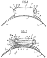
- the clamp as illustrated includes a band metallic 1 intended to surround in the form of a loop the object to tighten, not shown, for example a tube, sleeve, etc.
- a first end portion 2 of the strip 1 is secured to a cage 3, for example by being folded back on itself and fixed by a point of solder 4 (see figure 2).
- the second end part or part free end 5 of the strip 1 is provided with a longitudinal row of holes 6, for example of circular shape.
- the cage 3 is made up, as shown especially in FIG. 4, by a section of U-shaped profile, for example of sheet metal, the core of which 7 curved in an arc is surrounded by the end part 2 folded of the metal strip 1.
- the core 7 is extended, on the side opposite to the welding point 4 of the end part 2 of the strip 1, by two branches 8 in the form of fork teeth, spaced apart by a reciprocal distance slightly greater than the width of the strip metallic 1.
- the two wings 9 of the cage 3 in U are turned to the side outside of the clamp, i.e. opposite the object to tighten by the collar.
- a support 10 consisting of a U-shaped part with an external width slightly less than the inner width of the cage 3, so that the support 10 can be fitted from the outside of the hose clamp into the cage 3, its core 11 being turned towards the core 7 of the cage 3 and its two wings 12 being turned towards the outside of the clamp, everything like the wings 9 of the cage 3.
- a tooth 13 of triangular shape or trapezoidal is formed by cutting and folding, like a punctured, in the core 11 of the support 10, being inclined towards the side outside of the clamp and towards the welding point 4 when the support 10 is fitted into the cage 3.
- a nut 14 is pivotally mounted inside the support 10.
- the nut 14 comprises two opposite pins 15 mounted in rotation in the holes of the two wings 12 of the support 10 so that the nut 14 can pivot relative to the support 10 about an axis which is perpendicular to the threaded hole 16 of the nut 14.
- the nut 14 has a generally parallelepiped shape, the two pins 15 being provided on two opposite narrow sides of the nut 14.
- a wide side 17 of the nut 14 is spaced from the axis of pivot defined by the pins 15 so that when the nut 14 occupies the angular position according to FIG. 3 in which side 17 is facing the core 11 of the support 10, it remains between said side 17 and the free end of tooth 13 a distance greater than the thickness of the metallic strip 1.
- Another narrow side 18 of the nut 14 which is adjacent to the side 17 is curved in an arc centered on the axis defined by the pins 15, with a radius which, according to FIG. 2, is greater than the distance separating the tip of tooth 13 from the pivot axis of nut 14, but less than the distance separating the core 11 from the support 10 from the axis of pivoting of the nut 14.
- the side 18 of the nut 14 is also indented in 19, in the middle of its width 18, also in an arc centered on the pivot axis of the nut 14, so that the part median 19 is spaced from the pivot axis of the nut 14 by distance which, as shown in Figures 2 and 3, is greater than the distance separating the face 17 from the pivot axis of the nut 14, but less than the distance between the tip of tooth 13 from the axis of pivoting the nut 14.
- a clamping screw 20 bearing on its rod, between the nut 14 and its head 21, a stop 22 which can slide on the rod of the screw 20 and has two opposite ears 23 intended, when the screw 20 is in the tightening position, to cooperate with two opposite notches 24 formed in the two wings 9 of the cage 3, on the side facing the welding point 4 of the first end part 2 of the metallic strip 1.
- the cage 3 has, as especially shown in Figure 4, in each of its two wings 9 two inner projections 25 formed by local stampings.
- the support 10 present on its side, in the outer face of each of its two wings 12, two recesses 26 also constituted by two local stampings.
- the stamped upper in each wing 12 of the support 10 internally forms a projection 27 intended to cooperate, in the position of the nut following the Figure 3, with a recess 28 formed in the nut 14 in the flat side 29 opposite side 18, where it connects side 29 with each two opposite sides carrying the pins 15 (see Figure 1).
- the fitting of the clamp is carried out as described below.
- the support 10 is fitted into the cage 3 and held in position by cooperation of its recesses 26 with the bosses 25 of the cage 3.
- the screw 20 is engaged in nut 14 so that its end does not protrude the nut and is held in a position perpendicular to the base of the cage 3 by cooperation of the hollows 28 of the nut 14 with the bosses 27 of the support 10.
- the nut 14 releases the tooth 13, its face 17 being sufficiently spaced from tooth 13 so that the free end portion 5 of the metal strip 1, provided with holes 6, can be threaded into the space between the nut 14 and the base 11 of the support 10.
- the two curved lateral parts on the side 18 of the nut 14 press the free end part 5 of the strip 1 against the bottom 11 of support 10, on either side of tooth 13, to prevent part 5 to come out of tooth 13, and the middle part cylindrical 19 on the side 18 bears against the tip of the tooth 13 to prevent the latter from deforming under the tensile force tape 1.
- the clamping stroke of the collar, by tightening the screw 20, is depending on the length of the latter, as it appears on the Figure 5 which shows in broken line the position of the support 10, of the nut 14 and screw 20 at the start of tightening and in solid lines the position of these same elements at the end of tightening.
- the tightening by the traction screw 20 allows a torque of very important tightening which is only limited by the resistance to screw tension 20.
- the means for temporarily positioning the support 10 on the cage 3, formed here by hollows 26 and projections 25, could be replaced by other equivalent means.
- the arcuate surfaces 18 and 19 of the nut 14 cooperating with the part free end 5 of band 1 and with tooth 13, could also be modified or even deleted depending in particular the shape of tooth 13 which could be replaced by any other hooking lug.
Landscapes
- Engineering & Computer Science (AREA)
- General Engineering & Computer Science (AREA)
- Mechanical Engineering (AREA)
- Clamps And Clips (AREA)
Description
Claims (10)
- Collier de serrage comprenant une bande métallique (1) formant une boucle ouverte destinée à entourer l'objet à serrer, une cage (3) reliée à une première partie d'extrémité (2) de ladite bande, un écrou (14) relié par un axe d'articulation (15) parallèle à l'axe de la boucle formée par la bande (1) à un support (10) susceptible de coopérer avec la seconde partie d'extrémité (5) de la bande, une vis de serrage (20) engagée dans ledit écrou et une butée (22) montée mobile sur la vis, entre la tête (21) de cette dernière et l'écrou (14), pour permettre l'appui de la tête (21) de la vis contre la cage (3) en vue du serrage de la bande, caractérisé par le fait que le support (10) sur lequel est articulé l'écrou (14) comporte au moins une dent (13) faisant saillie sur le support en direction de l'écrou (14), que la bande métallique (1) présente, au moins dans sa seconde partie d'extrémité (5), une rangée longitudinale de trous (6) de telle manière que ladite seconde partie d'extrémité (5) de la bande métallique (1) puisse être enfilée dans le support (10), entre la dent (13) de ce dernier et l'écrou (14), et que ladite dent (13) puisse s'accrocher dans un trou (6) de la bande (1), pour rendre ainsi le support (10) solidaire de la bande seconde partie d'extrémité (5) de la bande métallique (1) en vue du serrage du collier par la vis (20).
- Collier de serrage suivant la revendication 1, caractérisé par le fait que l'écrou (14) comporte des moyens (19) pour empêcher la dent (13) du support (10) de se déformer sous l'effort de traction exercé sur la bande (1) lors du serrage.
- Collier de serrage suivant la revendication 2, caractérisé par le fait que l'écrou (14) comporte au moins un côté plat (17) perpendiculaire à l'axe de la vis (20) et un côté adjacent (18) ayant une partie médiane cylindrique (19) qui est centrée sur l'axe d'articulation (15) de l'écrou (14) et présente un rayon de courbure supérieur à la distance séparant ledit côté plat (17) de l'axe d'articulation (15), de façon normale audit côté plat.
- Collier de serrage suivant l'une quelconque des revendications précédentes, caractérisé par le fait que l'écrou (14 présente des moyens (18) empêchant la bande métallique (1) de se dégager de la dent (13) du support (10).
- Collier de serrage suivant la revendication 4, caractérisé par le fait que l'écrou (14) présente, sur son côté (18) adjacent audit côté plat (17), de part et d'autre de ladite partie médiane cylindrique (19), deux parties latérales cylindriques ayant un rayon de courbure supérieur à celui de la partie médiane cylindrique.
- Collier de serrage suivant l'une quelconque des revendications précédentes, caractérisé par le fait que la dent (13) du support (10) est inclinée en opposition au sens de la traction exercée sur la seconde partie d'extrémité (5) de la bande métallique (1) lors du serrage de la vis (20).
- Collier de serrage suivant la revendication 6, caractérisé par le fait que la dent (13) présente une forme triangulaire ou trapézoïdale et que les trous (6) de la bande métallique (1) sont des trous circulaires.
- Collier de serrage suivant l'une quelconque des revendications précédentes, caractérisé par le fait que la cage (3) et le support (10) comportent des moyens (25, 26, 27) de maintien provisoire du support (10) sur la cage (3), moyens dont l'action est automatiquement annulée lors du serrage de la vis (20).
- Collier de serrage suivant l'une quelconque des revendications précédentes, caractérisé par le fait que le support (10) et l'écrou (14) comportent des moyens (27, 28) de maintien provisoire de l'écrou (14) dans la position d'enfilage de la deuxième partie d'extrémité (5) de la bande métallique (1) entre l'écrou (14) et le support (10).
- Collier de serrage suivant la revendication 8 ou 9, caractérisé par le fait que les moyens de maintien provisoire comprennent des saillies (25, 27) sur l'une des pièces et des creux (26, 29) sur l'autre pièce, permettant un encliquetage par effet d'élasticité de l'une au moins des pièces.
Applications Claiming Priority (2)
| Application Number | Priority Date | Filing Date | Title |
|---|---|---|---|
| FR9500979A FR2730030B1 (fr) | 1995-01-27 | 1995-01-27 | Collier de serrage a reglage instantane |
| FR9500979 | 1995-01-27 |
Publications (2)
| Publication Number | Publication Date |
|---|---|
| EP0724107A1 EP0724107A1 (fr) | 1996-07-31 |
| EP0724107B1 true EP0724107B1 (fr) | 2000-05-17 |
Family
ID=9475585
Family Applications (1)
| Application Number | Title | Priority Date | Filing Date |
|---|---|---|---|
| EP19960400170 Expired - Lifetime EP0724107B1 (fr) | 1995-01-27 | 1996-01-25 | Collier de serrage à réglage instantané |
Country Status (3)
| Country | Link |
|---|---|
| EP (1) | EP0724107B1 (fr) |
| DE (1) | DE69608321T2 (fr) |
| FR (1) | FR2730030B1 (fr) |
Family Cites Families (3)
| Publication number | Priority date | Publication date | Assignee | Title |
|---|---|---|---|---|
| DE1249030B (de) * | 1961-10-11 | 1967-08-31 | Wolfgang Henning | Spannschelle |
| US3950830A (en) * | 1974-09-03 | 1976-04-20 | Standard-Thomson Corporation | Quick attachment and release worm gear type hose clamp |
| DE3130112A1 (de) * | 1981-07-30 | 1983-02-17 | Kurt 7238 Oberndorf Allert | Schlauchschelle |
-
1995
- 1995-01-27 FR FR9500979A patent/FR2730030B1/fr not_active Expired - Lifetime
-
1996
- 1996-01-25 EP EP19960400170 patent/EP0724107B1/fr not_active Expired - Lifetime
- 1996-01-25 DE DE1996608321 patent/DE69608321T2/de not_active Expired - Lifetime
Also Published As
| Publication number | Publication date |
|---|---|
| DE69608321D1 (de) | 2000-06-21 |
| EP0724107A1 (fr) | 1996-07-31 |
| DE69608321T2 (de) | 2001-02-15 |
| FR2730030A1 (fr) | 1996-08-02 |
| FR2730030B1 (fr) | 1998-01-23 |
Similar Documents
| Publication | Publication Date | Title |
|---|---|---|
| EP2017518B1 (fr) | Dispositif de serrage avec collier de serrage et pièce de positionnement | |
| EP0434825B1 (fr) | Ecrou rapide | |
| EP0571294B1 (fr) | Collier de serrage à vis | |
| EP0724106A1 (fr) | Collier de serrage | |
| EP0697934A1 (fr) | Monture de scie | |
| CH661185A5 (en) | Watch bracelet | |
| FR2842276A1 (fr) | Collier de serrage | |
| EP4480729B1 (fr) | Dispositif de serrage d'un objet comprenant une ceinture | |
| FR3002601A1 (fr) | Dispositif de maintien et de positionnement d'elements allonges, tels que des cables | |
| EP0754868B1 (fr) | Attache pour la fixation réglable de deux pièces espacées | |
| EP2446155B1 (fr) | Dispositif de fixation a ecrou plastique | |
| EP0724107A1 (fr) | Collier de serrage à réglage instantané | |
| EP1141563B1 (fr) | Procede et dispositif pour le blocage anti-rotation d'un ecrou sur une tige filetee | |
| FR2617784A1 (fr) | Compensateur de frein a main | |
| EP0378969A1 (fr) | Charnière de lunettes | |
| EP0851264A1 (fr) | Charnière élastique | |
| EP0004814B1 (fr) | Manille perfectionnée | |
| EP0323338B1 (fr) | Dispositif de jonction de deux brides espacées d'assemblage d'un tuyau d'échappement | |
| FR2756356A1 (fr) | Collier de serrage a boitier elastique | |
| FR2802455A1 (fr) | Dispositif d'extracteur d'electrode | |
| FR2754435A1 (fr) | Fermoir a boucle deployante comprenant une genouillere | |
| FR2491690A3 (fr) | Pince a denuder les fils ou cables electriques | |
| CA1122833A (fr) | Dispositif de serrage ou de blocage d'un objet sur une tige | |
| FR2918095A1 (fr) | Ensemble pour une grille barreaudee | |
| FR2506528A1 (fr) | Dispositif de connexion destine au raccordement d'une extremite d'un fil a un appareil electrique |
Legal Events
| Date | Code | Title | Description |
|---|---|---|---|
| PUAI | Public reference made under article 153(3) epc to a published international application that has entered the european phase |
Free format text: ORIGINAL CODE: 0009012 |
|
| AK | Designated contracting states |
Kind code of ref document: A1 Designated state(s): DE GB |
|
| 17P | Request for examination filed |
Effective date: 19970114 |
|
| GRAG | Despatch of communication of intention to grant |
Free format text: ORIGINAL CODE: EPIDOS AGRA |
|
| 17Q | First examination report despatched |
Effective date: 19990730 |
|
| GRAG | Despatch of communication of intention to grant |
Free format text: ORIGINAL CODE: EPIDOS AGRA |
|
| GRAH | Despatch of communication of intention to grant a patent |
Free format text: ORIGINAL CODE: EPIDOS IGRA |
|
| GRAH | Despatch of communication of intention to grant a patent |
Free format text: ORIGINAL CODE: EPIDOS IGRA |
|
| GRAA | (expected) grant |
Free format text: ORIGINAL CODE: 0009210 |
|
| AK | Designated contracting states |
Kind code of ref document: B1 Designated state(s): DE GB |
|
| REF | Corresponds to: |
Ref document number: 69608321 Country of ref document: DE Date of ref document: 20000621 |
|
| GBT | Gb: translation of ep patent filed (gb section 77(6)(a)/1977) |
Effective date: 20000809 |
|
| PLBE | No opposition filed within time limit |
Free format text: ORIGINAL CODE: 0009261 |
|
| STAA | Information on the status of an ep patent application or granted ep patent |
Free format text: STATUS: NO OPPOSITION FILED WITHIN TIME LIMIT |
|
| 26N | No opposition filed | ||
| REG | Reference to a national code |
Ref country code: GB Ref legal event code: IF02 |
|
| PGFP | Annual fee paid to national office [announced via postgrant information from national office to epo] |
Ref country code: DE Payment date: 20150109 Year of fee payment: 20 |
|
| PGFP | Annual fee paid to national office [announced via postgrant information from national office to epo] |
Ref country code: GB Payment date: 20150114 Year of fee payment: 20 |
|
| REG | Reference to a national code |
Ref country code: DE Ref legal event code: R071 Ref document number: 69608321 Country of ref document: DE |
|
| REG | Reference to a national code |
Ref country code: GB Ref legal event code: PE20 Expiry date: 20160124 |
|
| PG25 | Lapsed in a contracting state [announced via postgrant information from national office to epo] |
Ref country code: GB Free format text: LAPSE BECAUSE OF EXPIRATION OF PROTECTION Effective date: 20160124 |