EP0723902B1 - Vehicle state observer system - Google Patents
Vehicle state observer system Download PDFInfo
- Publication number
- EP0723902B1 EP0723902B1 EP95120686A EP95120686A EP0723902B1 EP 0723902 B1 EP0723902 B1 EP 0723902B1 EP 95120686 A EP95120686 A EP 95120686A EP 95120686 A EP95120686 A EP 95120686A EP 0723902 B1 EP0723902 B1 EP 0723902B1
- Authority
- EP
- European Patent Office
- Prior art keywords
- vehicle
- observer
- state
- pole
- variable
- Prior art date
- Legal status (The legal status is an assumption and is not a legal conclusion. Google has not performed a legal analysis and makes no representation as to the accuracy of the status listed.)
- Expired - Lifetime
Links
Images


Classifications
-
- B—PERFORMING OPERATIONS; TRANSPORTING
- B62—LAND VEHICLES FOR TRAVELLING OTHERWISE THAN ON RAILS
- B62D—MOTOR VEHICLES; TRAILERS
- B62D6/00—Arrangements for automatically controlling steering depending on driving conditions sensed and responded to, e.g. control circuits
-
- B—PERFORMING OPERATIONS; TRANSPORTING
- B62—LAND VEHICLES FOR TRAVELLING OTHERWISE THAN ON RAILS
- B62D—MOTOR VEHICLES; TRAILERS
- B62D7/00—Steering linkage; Stub axles or their mountings
- B62D7/06—Steering linkage; Stub axles or their mountings for individually-pivoted wheels, e.g. on king-pins
- B62D7/14—Steering linkage; Stub axles or their mountings for individually-pivoted wheels, e.g. on king-pins the pivotal axes being situated in more than one plane transverse to the longitudinal centre line of the vehicle, e.g. all-wheel steering
- B62D7/15—Steering linkage; Stub axles or their mountings for individually-pivoted wheels, e.g. on king-pins the pivotal axes being situated in more than one plane transverse to the longitudinal centre line of the vehicle, e.g. all-wheel steering characterised by means varying the ratio between the steering angles of the steered wheels
- B62D7/159—Steering linkage; Stub axles or their mountings for individually-pivoted wheels, e.g. on king-pins the pivotal axes being situated in more than one plane transverse to the longitudinal centre line of the vehicle, e.g. all-wheel steering characterised by means varying the ratio between the steering angles of the steered wheels characterised by computing methods or stabilisation processes or systems, e.g. responding to yaw rate, lateral wind, load, road condition
Definitions
- the present invention relates to a vehicle state observer system which estimates a motion state of a vehicle.
- a vehicle state observer system for use in an automotive vehicle is known. "Introduction to Modern Control Theory" by M. Shiraishi published on November 25, 1987 from Keigaku Shuppan Co. in Japan teaches a vehicle state observer system which estimates a quantity of motion state of a vehicle.
- the vehicle state observer system of the above type includes an observable state measuring unit which measures an observable quantity of state of a vehicle.
- a controlled variable detecting unit in the vehicle state observer system detects a controlled variable of the vehicle.
- An observer in the vehicle state observer system estimates an unobservable quantity of state of the vehicle from the measured observable quantity and from the detected controlled variable in accordance with a system matrix including a system variable.
- the above vehicle state observer system estimates the quantities of state of the vehicle by maintaining a pole of the observer at a fixed point so as to optimize an error between the pole of the observer and a pole of a system.
- G(s) N(s)/D(s) where s is a complex number, N(s) is a numerator polynomial, and D(s) is a denominator polynomial.
- the numerator polynomial N(s) is indicative of the measured quantity, and the denominator polynomial D(s) is indicative of the controlled variable.
- the numerator polynomial N'(s) is indicative of the observed quantity, and the denominator polynomial D'(s) is indicative of the controlled variable.
- the pole of the system mentioned above means a solution obtained by putting the denominator polynomial D(s) of the transfer function of the system equal to zero.
- the pole of the observer is greater than the pole of the system, it is impossible to estimate the quantities of state of the vehicle. Therefore, in the conventional system, the pole of the observer is maintained at the fixed point which is smaller than the pole of the system.
- the system variable which is included in the system matrix is changed, and the stability of the system is changed in accordance with the change of the system variable.
- the system variable is, for example, a vehicle speed, a vehicle weight, etc. Therefore, the pole of the system is changed in accordance with the change of the system variable. For example, when the system variable is changed, the system becomes more instable and the pole of the system becomes greater than before.
- the pole of the observer is maintained at the fixed point.
- the error between the pole of the observer and the pole of the system may be greater in accordance with the change of the system variable. If the error between the pole of the observer and the pole of the system is greater than a reference value, the accuracy of estimated quantities of state of the vehicle becomes low and the accuracy thereof may scatter.
- the above vehicle state observer system may experience the scattering of the accuracy of estimated quantities of state of the vehicle when the system variable is changed.
- An object of the present invention is to provide an improved vehicle state observer system in which the above-described problem is eliminated.
- Another object of the present invention is to provide a vehicle state observer system in which a transition of the pole of the observer follows a transition of the pole of the system, so that the error between the pole of the observer and the pole of the system is maintained to be constant even when the pole of the system is changed in response to the change of the system variable.
- a vehicle state observer system which includes a state quantity measuring unit which measures an observable quantity of state of a vehicle, a controlled variable detecting unit which detects a controlled variable of the vehicle, an observer which estimates an unobservable quantity of state of the vehicle from the observable quantity measured by the state quantity measuring unit and the controlled variable detected by the controlled variable detecting unit, based on a system matrix including a system variable, a system variable detecting unit which detects the system variable included in the system matrix, and a correcting unit which corrects a pole of the observer in response to the system variable detected by the system variable detecting unit.
- the system variable detecting unit detects a change of the system variable
- the correcting unit corrects the pole of the observer in accordance with the change of the system variable and makes it possible to prevent the scattering of the accuracy of estimated quantities of state of the vehicle even when the pole of the system is changed in response to the change of the system variable. Therefore, the vehicle state observer system of the present invention estimates the unobservable quantity of state of the vehicle with accuracy.
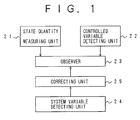
- FIG.1 shows a vehicle state observer system in one embodiment of the present invention.
- the vehicle state observer system includes a state quantity measuring unit 21 which measures an observable quantity of state of a vehicle.
- a controlled variable detecting unit 22 detects a controlled variable of the vehicle.
- An observer 23 estimates an unobservable quantity of state of the vehicle from the observable quantity measured by the state quantity measuring unit 21 and the controlled variable detected by the controlled variable detecting unit 22, in accordance with a system matrix including a system variable.
- a system variable detecting unit 24 detects the system variable included in the system matrix.
- a correcting unit 25 determines a corrected pole of the observer 23 in accordance with the system variable detected by the system variable detecting unit 24.
- the correcting unit 25 determines the corrected pole of the observer 23 in accordance with the system variable detected by the system variable detecting unit 24.
- the pole of the observer 23 is changed to the corrected pole determined by the correcting unit 25.
- the observer 23 estimates the unobservable quantity of state of the vehicle from the observable quantity measured by the state quantity measuring unit 21 and the controlled variable detected by the controlled variable detecting unit 22, in accordance with the system matrix.
- the vehicle state observer system of the present invention allows a transition of the pole of the observer to follow a transition of the pole of the system, thereby maintaining the error between the pole of the observer and the pole of the system to be constant even when the pole of the system is changed in accordance with the change of the system variable. Therefore, the vehicle state observer system of the present invention can prevent the scattering of the accuracy of estimated quantities of state of the vehicle even when the pole of the system is changed in accordance with the change of the system variable.
- a yaw rate ⁇ and a lateral slip angle ⁇ are taken as quantities of state of a vehicle.
- a system in which rear wheels of the vehicle are manipulated to control the quantities of state of the vehicle will be considered.
- a vehicle model which is represented with two degrees of freedom is taken as a controlled system.
- the yaw rate ⁇ , the lateral slip angle ⁇ , a vehicle speed V, a front-wheel steering angle ⁇ f, and a rear-wheel steering angle ⁇ r are variables of the vehicle model which are defined by the following equations.
- x is a state vector
- u is a control vector
- A is a system matrix
- B is a control matrix
- the relationship between the yaw rate ⁇ , the lateral slip angle ⁇ , the vehicle speed V, the front-wheel steering angle ⁇ f and the rear-wheel steering angle ⁇ r is defined as in the above Equations (1) through (5).
- the yaw rate ⁇ can be easily measured by using a yaw rate sensor.
- the yaw rate ⁇ is an observable state of the vehicle which is sensed by the yaw rate sensor.
- it is difficult to detect the lateral slip angle ⁇ it is assumed that the lateral slip angle ⁇ is an unobservable state of the vehicle which is estimated by the observer.
- y is an output vector and C is an output matrix.
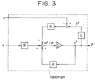
- FIG.3 shows an observer which is provided in correspondence to the vehicle model defined by the above Equations (1)-(7). This observer is of the same degree as the above vehicle model.
- a state equation of the observer shown in FIG.3 is as follows.
- x* is an estimated value of the state vector x
- dx*/dt is a derivative of the estimated value x*
- K is a feedback gain of the observer.
- the observer inputs the measured yaw rate ⁇ and the detected control vector u, and generates an estimated value x* of the state vector x from these inputs based on the state equation defined by the above Equation (8).
- the observer defined by the above Equation (8) generates an estimated lateral slip angle ⁇ * and an estimated yaw rate ⁇ * from the measured yaw rate ⁇ from the yaw rate sensor, the detected front-wheel steering angle ⁇ f from a front-wheel steering angle sensor, and the detected rear-wheel steering angle ⁇ r from a rear-wheel steering angle sensor.
- the front-wheel steering angle ⁇ f and the rear-wheel steering angle ⁇ r are taken as the controlled variables.
- a pole of the observer defined by the above Equation (8) means a solution obtained by putting the denominator polynomial D'(s) of the transfer function of the observer equal to zero.
- the solution, which is the pole of the observer, is equivalent to an eigenvalue of the matrix (A - KC).
- FIG.4 shows a transition of the pole of the system (or the vehicle model) in accordance with a change of the system variable (or the vehicle speed V) on a complex plane.
- a vehicle speed V sensed by a vehicle speed sensor is taken as the system variable.
- the vehicle speed V is one of the system variables which are included in the system matrix A.
- the system matrix A defined by the above formula (4) includes the vehicle speed V as the system variable. As the vehicle speed V varies, the element included in the system matrix A varies accordingly.
- G(s) N(s)/D(s) where s is a complex number, N(s) is a numerator polynomial (which is indicative of the measured quantity), and D(s) is a denominator polynomial (which is indicative of the controlled variable).
- a pole of the system is a solution obtained by putting the denominator polynomial D(s) of the transfer function of the system equal to zero.
- the solution, or the pole of the system is equivalent to an eigenvalue of the system matrix A.
- the system matrix A in the present embodiment is a 2 x 2 square matrix as indicated by the above formula (4).
- the poles p1 and p2 of the system are plotted with "*" and "o” respectively in accordance with the increase of the vehicle speed V from 10 km/h to 180 km/h.
- each of the poles p1 and p2 of the system in accordance with the change of the vehicle speed V is indicated by the arrow in FIG.4.
- the stability of the vehicle is reduced as the vehicle speed is increased.
- the real part of each of the poles p1 and p2 of the system approaches zero (which is the origin of the complex plane) in accordance with the increase of the vehicle speed V.
- the real part of each of the poles p1 and p2 of the system becomes greater in accordance with the increase of the vehicle speed V.
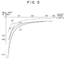
- FIG.5 shows a relationship between the vehicle speed and the real part of the pole of the system.
- a transition of each of the real parts of the poles p1 and p2 of the system in accordance with the increase of the vehicle speed V is indicated by a dotted line. It is observed that the real parts of the poles p1 and p2 of the system are increased in accordance with the increase of the vehicle speed V.
- the two poles p1 and p2 of the system are indicated as two distinct real numbers (FIG.4). So there are two real parts of the poles of the system for a value of the vehicle speed V when the vehicle speed V is in the low speed range.
- the two poles p1 and p2 of the system are indicated as two conjugate complex numbers (FIG.4). So there is one real part of the poles of the system for a value of the vehicle speed V when the vehicle speed V is in the high speed range.
- each of the poles p1 and p2 of the system in accordance with the increase of the vehicle speed V is predetermined by calculating the eigenvalues of the system matrix A in accordance with the increase of the vehicle speed V.
- the observer includes two poles p11 and p12 which are defined as a function of the vehicle speed V.
- the poles of the observer are corrected such that the transition of each of the poles p11 and p12 of the observer follows the transition of the poles p1 and p2 of the system in accordance with a change of the vehicle speed V.
- p12 -7.0 - 720/V (-60 ⁇ p12)
- the feedback gain K of the observer is controlled so that the poles p11 and p12 vary in accordance with the change of the vehicle speed V as defined by the above Equations (9) and (10).
- the poles p11 and p12 of the observer in the present embodiment are corrected in accordance with the functions defined by the above Equations (9) and (10).
- the transition of each of the poles p11 and p12 of the observer in accordance with the increase of the vehicle speed V is indicated by a solid line in FIG.5.
- the transition of the poles p11 and p12 of the observer follows the transition of the poles p1 and p2 of the system, respectively.
- the observer in the present embodiment generates an estimated lateral slip angle ⁇ * and an estimated yaw rate ⁇ * from the measured yaw rate ⁇ , the detected front-wheel steering angle ⁇ f and the detected rear-wheel steering angle ⁇ r in accordance with the above Equation (8), based on a corrected pole of the observer obtained by the above Equations (9) and (10).
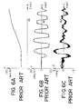
- FIGS.6A, 6B and 6C shows an estimation result of a conventional vehicle state observer system.
- FIG.6A is a time chart indicating a relationship between time t and vehicle speed V when an experiment is performed with the conventional system.
- FIG.6B an error between an estimated yaw rate (indicated by a dotted line) from the pole-fixed observer of the conventional system and a measured yaw rate (indicated by a solid line) from a yaw rate measuring instrument is shown.
- FIG.6C an error between an estimated lateral slip angle (indicated by a dotted line) from the pole-fixed observer of the conventional system and a measured lateral slip angle (indicated by a solid line) from a lateral slip angle measuring instrument is shown.
- the accuracy of the estimated yaw rate is highest when the vehicle speed V is around 50 km/h, and the accuracy of the estimated lateral slip angle is relatively high throughout the whole range of the vehicle speed V since the poles of the observer are preset at a suitable fixed point.
- the poles of the observer are preset such that the accuracy of the estimated lateral slip angle is relatively high.
- the difference between the estimated lateral slip angle and the measured value is relatively great when the vehicle speed V is high.
- FIGS.7A, 7B and 7C shows an estimation result of the vehicle state observer system in the present embodiment by comparison with the estimation result of FIGS.6A, 6B and 6C.
- FIG.7A is a time chart indicating a relationship between time t and vehicle speed V when an experiment is performed with the vehicle state observer system in the present embodiment.
- FIG.7B an error between an estimated yaw rate (indicated by a dotted line) from the observer of the present embodiment and a measured yaw rate (indicated by a solid line) from the yaw rate measuring instrument is shown.
- FIG.7C an error between an estimated lateral slip angle (indicated by a dotted line) from the observer of the present embodiment and a measured lateral slip angle (indicated by a solid line) from the lateral slip angle measuring instrument is shown.
- the poles p11 and p12 of the observer in the present embodiment are defined by the above Equations (9) and (10) as a function of the vehicle speed V, allowing the transition of the poles p11 and p12 of the observer to follow the transition of the poles p1 and p2 of the system. It is found that, when the vehicle speed is increased, the error between the estimated yaw rate and the measured value and the error between the estimated lateral slip angle and the measured value are negligible, as shown in FIGS.7B and 7C.
- the lateral slip angle measuring instrument utilizes a Doppler sensor which senses a vehicle speed in the aft-and-fore direction and a vehicle speed in the right-and-left direction. By using the lateral slip angle measuring instrument, an angle of a vector sum of the sensed vehicle speeds to the aft-and-fore direction is determined.
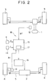
- FIG.2 shows a four-wheel steering system to which the embodiment of the present invention is applied.
- the four-wheel steering system shown in FIG.2, controls the steering of the rear wheels in accordance with an estimated quantity of state of the vehicle from the vehicle state observer system including the observer in the present embodiment.
- the two poles p11 and p12 of the observer are defined by the above Equations (9) and (10) as a function of the vehicle speed V.
- a controlled quantity to manipulate the rear wheels of the vehicle is determined in accordance with an estimated quantity of state of the vehicle from the vehicle state observer system of the present invention.
- the four-wheel steering system shown in FIG.2 includes a steering wheel 1 which is used by a vehicle operator to steer front wheels 3 of a vehicle, and an actuator 2 which is used to steer rear wheels 4 of the vehicle.
- a rear wheel steering mechanism is formed by the actuator 2 and a relay rod 5, the relay rod 5 being linked to the rear wheels 4 to allow the steering of the rear wheels 4.
- the actuator 2 actuates the relay rod 5 in an axial direction of the relay rod 5 so that the steering of the rear wheels 4 is controlled by the actuator 2.
- the four-wheel steering system further includes an electric control unit 18 which controls the actuator 2.
- the electric control unit 18 is provided within the vehicle on which the four-wheel steering system is mounted.
- the electric control unit 18 includes a vehicle speed sensor 11 which senses the vehicle speed V, a front-wheel steering angle sensor 12 which senses the front-wheel steering angle ⁇ f, a rear-wheel steering angle sensor 13 which senses the rear-wheel steering angle ⁇ r, and a yaw rate sensor 14 which senses the yaw rate ⁇ .
- the yaw rate ⁇ which is an observable quantity of state of the vehicle is sensed by the yaw rate sensor 14.
- Outputs of the above-described sensors 11, 12, 13 and 14 are connected to respective inputs of a microcomputer 15.
- An observer 17 including the two poles p11 and p12 defined by the above Equations (9) and (10) is provided in the microcomputer 15.
- the above Equations (9) and (10) are stored in a portion of the microcomputer 15.
- a desired steering quantity determining unit which determines a desired steering quantity relating to the rear wheels 4 in accordance with an estimated yaw rate and an estimated lateral slip angle is stored in the microcomputer 15.
- An output of the microcomputer 15 is connected to an input of an actuator drive circuit 16.
- An output of the actuator drive circuit 16 is connected to an input of the actuator 2.
- the actuator drive circuit 16 controls the actuator 2 in accordance with the desired rear-wheel steering quantity indicated by a signal output by the above desired steering quantity determining unit, so that the steering of the rear wheels 4 is controlled by the actuator 2.
- the observer 17, provided in the microcomputer 15, generates an estimated yaw rate and an estimated lateral slip angle from various measured quantities including a measured yaw rate ⁇ from the yaw rate sensor 14, a measured front-wheel steering angle ⁇ f from the front-wheel steering angle sensor 12, a measured rear-wheel steering angle ⁇ r from the rear-wheel steering angle sensor 13, and a measured vehicle speed V from the vehicle speed sensor 11.
- the desired steering quantity determining unit determines a desired rear-wheel steering quantity in accordance with the estimated yaw rate and the estimated lateral slip angle from the observer 17.
- the desired steering quantity determining unit outputs a signal indicative of the desired rear-wheel steering quantity, to the actuator drive circuit 16.
- the actuator drive circuit 16 receives the desired rear-wheel steering quantity signal from the desired steering quantity determining unit (or from the output of the microcomputer 15), and controls the steering of the rear wheels 4 through the actuator 2 in accordance with the desired rear-wheel steering quantity signal.
- the state quantity measuring unit 21 is constituted by the yaw rate sensor 14 which senses the yaw rate ⁇ of the vehicle.
- the controlled variable detecting unit 22 is constituted by the front-wheel steering angle sensor 12 which senses the front-wheel steering angle ⁇ f and by the rear-wheel steering angle sensor 13 which senses the rear-wheel steering angle ⁇ r.
- the system variable detecting unit 24 is constituted by the vehicle speed sensor 11 which senses the vehicle speed V.
- the correcting unit 25 and the observer 23 are constituted by portions of the microcomputer 15 wherein the above Equations (9) and (10) are stored and the feedback gain K of the observer 23 is determined in accordance with the results of calculations on the above Equations (9) and (10).
- the above Equations (9) and (10) are the function of the system variable included in the system matrix A.
- the system variable in the present embodiment is the vehicle speed V.
- the equations included in the correcting unit 25 are not limited to the above Equations (9) and (10). Also, the coefficients included in the above Equations (9) and (10) may be modified to other suitable values. Also, the system variable detected by the system variable detecting unit 24 is not limited to the vehicle speed V. The vehicle weight M may be detected instead of the vehicle speed V.
- the correcting unit 25 corrects a pole of the observer in accordance with the relation of the pole of the system with a predetermined change of the system variable, such that the transition of the pole of the observer follows the transition of the pole of the system.
- the correcting unit in the present embodiment generates a corrected pole of the observer as the function of the system variable without detecting the present value of the pole of the system.
- the correcting unit according to the present invention is not limited to the present embodiment. It is also possible to provide a correcting unit which detects a current value of the pole of the system and determines the pole of the observer in accordance with the detected current value of the pole of the system.
- the above-described embodiment of the present invention is applied to the four-wheel steering system.
- the present invention is not limited to the above-described embodiment.
- the vehicle state observer system of the present invention may be suitably applied to an antilock brake system, a traction control system, or any other system.
- a vehicle state observer system includes a state quantity measuring unit (21) which measures an observable quantity of state of a vehicle.
- a controlled variable detecting unit (22) detects a controlled variable of the vehicle.
- An observer (23) estimates an unobservable quantity of state of the vehicle from the observable quantity measured by the state quantity measuring unit and the controlled variable detected by the controlled variable detecting unit, in accordance with a system matrix including a system variable.
- a system variable detecting unit (24) detects the system variable included in the system matrix.
- a correcting unit (25) corrects a pole of the observer in response to the system variable detected by the system variable detecting unit.
Landscapes
- Engineering & Computer Science (AREA)
- Combustion & Propulsion (AREA)
- Mechanical Engineering (AREA)
- Transportation (AREA)
- Chemical & Material Sciences (AREA)
- Theoretical Computer Science (AREA)
- Physics & Mathematics (AREA)
- Mathematical Physics (AREA)
- Steering Control In Accordance With Driving Conditions (AREA)
- Vehicle Body Suspensions (AREA)
- Control Of Driving Devices And Active Controlling Of Vehicle (AREA)
- Regulating Braking Force (AREA)
- Feedback Control In General (AREA)
Description
Claims (8)
- A vehicle state observer system which includesa state quantity measuring means which measures an observable quantity of state of a vehicle,a controlled variable detecting means which detects a controlled variable of the vehicle, andan observer which estimates an unobservable quantity of state of the vehicle from the observable quantity measured by said state quantity measuring means and the controlled variable detected by said controlled variable detecting means, in accordance with a system matrix including a system variable, andsystem variable detecting means (24) which detects the system variable included in the system matrix;
characterized in that said vehicle state observer system comprises:correcting means (25) which corrects a pole of said observer (23) in response to the system variable detected by said system variable detecting means (24). - The vehicle state observer system according to claim 1, characterized in that said observer (23) generates an estimated unobservable quantity of state of the vehicle and an estimated observable quantity of state of the vehicle from the measured observable quantity and the detected controlled variable based on a corrected pole of the observer from said correcting means (25).
- The vehicle state observer system according to claim 1, characterized in that a transition of a pole of a vehicle model is determined by calculating an eigenvalue of the system matrix (A) in accordance with a change of the system variable (V).
- The vehicle state observer system according to claim 1, characterized in that said vehicle state observer system determines a feedback gain (K) of the observer (23) such that a transition of a corrected pole of the observer from the correcting means (25) follows a transition of a pole of a vehicle model in accordance with a change of the system variable.
- The vehicle state observer system according to claim 1, characterized in that said correcting means (25) and said observer (23) are provided in a microcomputer (15), said correcting means (25) including a predetermined function of the system variable (V) by which a corrected pole (p11, p12) of the observer in accordance with a change of the system variable (V) is defined.
- The vehicle state observer system according to claim 1, characterized in that said controlled variable detecting means (22) includes a front-wheel steering angle sensor (12) which senses a steering angle of front wheels of the vehicle and a rear-wheel steering angle sensor (13) which senses a steering angle of rear wheels of the vehicle.
- The vehicle state observer system according to claim 1, characterized in that said state quantity measuring means (21) includes a yaw rate sensor (14) which senses a yaw rate of the vehicle.
- The vehicle state observer system according to claim 1, characterized in that said system variable detecting means (24) includes a vehicle speed sensor (11) which senses a vehicle speed of the vehicle as the system variable included in the system matrix.
Applications Claiming Priority (2)
| Application Number | Priority Date | Filing Date | Title |
|---|---|---|---|
| JP10782/95 | 1995-01-26 | ||
| JP7010782A JPH08202403A (en) | 1995-01-26 | 1995-01-26 | Vehicle state quantity estimation device |
Publications (3)
| Publication Number | Publication Date |
|---|---|
| EP0723902A2 EP0723902A2 (en) | 1996-07-31 |
| EP0723902A3 EP0723902A3 (en) | 1997-07-23 |
| EP0723902B1 true EP0723902B1 (en) | 1998-11-04 |
Family
ID=11759913
Family Applications (1)
| Application Number | Title | Priority Date | Filing Date |
|---|---|---|---|
| EP95120686A Expired - Lifetime EP0723902B1 (en) | 1995-01-26 | 1995-12-28 | Vehicle state observer system |
Country Status (6)
| Country | Link |
|---|---|
| US (1) | US5652379A (en) |
| EP (1) | EP0723902B1 (en) |
| JP (1) | JPH08202403A (en) |
| KR (1) | KR0155030B1 (en) |
| CN (1) | CN1134897A (en) |
| DE (1) | DE69505782T2 (en) |
Cited By (1)
| Publication number | Priority date | Publication date | Assignee | Title |
|---|---|---|---|---|
| WO2017178722A1 (en) | 2016-04-13 | 2017-10-19 | Renault Sas | Device for tracking the path of a vehicle |
Families Citing this family (15)
| Publication number | Priority date | Publication date | Assignee | Title |
|---|---|---|---|---|
| JP3707199B2 (en) * | 1997-04-28 | 2005-10-19 | 日産自動車株式会社 | Automatic vehicle steering system |
| US6148261A (en) | 1997-06-20 | 2000-11-14 | American Calcar, Inc. | Personal communication system to send and receive voice data positioning information |
| US6133853A (en) * | 1998-07-30 | 2000-10-17 | American Calcar, Inc. | Personal communication and positioning system |
| KR100697833B1 (en) * | 1998-10-21 | 2007-03-20 | 아메리칸 캘카어 인코포레이티드 | Positional camera and gps data interchange device |
| WO2001029573A2 (en) * | 1999-10-19 | 2001-04-26 | American Calcar Inc. | Technique for effective navigation based on user preferences |
| JP2003517164A (en) | 1999-10-27 | 2003-05-20 | アメリカン カルカー インコーポレイテッド | User navigation system and method |
| KR20030022876A (en) * | 2000-07-28 | 2003-03-17 | 아메리칸 캘카어 인코포레이티드 | Technique for effective organization and communication of information |
| US6560524B2 (en) * | 2001-09-26 | 2003-05-06 | General Motors Corporation | Integration of rear wheel steering with vehicle stability enhancement system |
| FR2864002B1 (en) * | 2003-12-18 | 2006-03-17 | Renault Sas | METHOD AND SYSTEM FOR CONTROLLING THE DIRECT REAR WHEEL BRAKE AND CORRESPONDING VEHICLE |
| FR2864003B1 (en) * | 2003-12-18 | 2006-03-17 | Renault Sas | METHOD AND SYSTEM FOR CONTROLLING THE DIRECT REAR WHEEL BRAKE AND CORRESPONDING VEHICLE |
| JP4379458B2 (en) * | 2006-10-12 | 2009-12-09 | 三菱自動車工業株式会社 | Data recorder |
| JP5668359B2 (en) * | 2010-08-11 | 2015-02-12 | トヨタ自動車株式会社 | Vehicle control device |
| JP6764292B2 (en) * | 2016-09-16 | 2020-09-30 | Ntn株式会社 | Anti-slip control device |
| US10216198B2 (en) | 2017-03-21 | 2019-02-26 | The Boeing Company | Methods and apparatus to perform observer-based control of a vehicle |
| DE102021201141A1 (en) * | 2021-02-08 | 2022-08-11 | Continental Automotive Gmbh | Control device and method for steering angle control of a vehicle |
Family Cites Families (13)
| Publication number | Priority date | Publication date | Assignee | Title |
|---|---|---|---|---|
| JP3008401B2 (en) * | 1988-08-08 | 2000-02-14 | 日産自動車株式会社 | Vehicle state quantity estimation device |
| US4884412A (en) * | 1988-09-15 | 1989-12-05 | William Sellers | Compressor slugging protection device and method therefor |
| JPH02106471A (en) * | 1988-10-14 | 1990-04-18 | Nissan Motor Co Ltd | Movement state quantity estimating device for vehicle |
| US5200899A (en) * | 1990-04-20 | 1993-04-06 | Regents Of The University Of Michigan | Method and system for detecting the misfire of an internal combustion engine utilizing angular velocity fluctuations |
| JPH04224260A (en) * | 1990-12-26 | 1992-08-13 | Nippondenso Co Ltd | Combustion condition detecting device for internal combustion engine |
| JPH05312085A (en) * | 1992-05-07 | 1993-11-22 | Nippondenso Co Ltd | Rough detector |
| JP3059827B2 (en) * | 1992-06-25 | 2000-07-04 | 本田技研工業株式会社 | Road surface condition determination device |
| US5345398A (en) * | 1992-09-11 | 1994-09-06 | Delco Electronics Corporation | Gauge glider |
| US5394330A (en) * | 1992-11-12 | 1995-02-28 | Texas Instruments Incorporated | System and method for monitoring an operating state of an engine |
| KR0141893B1 (en) * | 1993-06-30 | 1998-06-01 | 나까무라 유이찌 | Fault diagnosis apparatus and method for vehicle control system |
| JP2952151B2 (en) * | 1993-07-30 | 1999-09-20 | トヨタ自動車株式会社 | Wheel disturbance detection device and its use |
| JP2807736B2 (en) * | 1993-08-19 | 1998-10-08 | 本田技研工業株式会社 | Device for determining combustion state of internal combustion engine |
| US5495415A (en) * | 1993-11-18 | 1996-02-27 | Regents Of The University Of Michigan | Method and system for detecting a misfire of a reciprocating internal combustion engine |
-
1995
- 1995-01-26 JP JP7010782A patent/JPH08202403A/en active Pending
- 1995-10-19 KR KR1019950036817A patent/KR0155030B1/en not_active IP Right Cessation
- 1995-12-14 US US08/572,733 patent/US5652379A/en not_active Expired - Lifetime
- 1995-12-28 EP EP95120686A patent/EP0723902B1/en not_active Expired - Lifetime
- 1995-12-28 DE DE69505782T patent/DE69505782T2/en not_active Expired - Fee Related
-
1996
- 1996-01-24 CN CN96100678A patent/CN1134897A/en active Pending
Cited By (1)
| Publication number | Priority date | Publication date | Assignee | Title |
|---|---|---|---|---|
| WO2017178722A1 (en) | 2016-04-13 | 2017-10-19 | Renault Sas | Device for tracking the path of a vehicle |
Also Published As
| Publication number | Publication date |
|---|---|
| US5652379A (en) | 1997-07-29 |
| KR0155030B1 (en) | 1998-10-15 |
| KR960029187A (en) | 1996-08-17 |
| EP0723902A3 (en) | 1997-07-23 |
| DE69505782T2 (en) | 1999-05-20 |
| CN1134897A (en) | 1996-11-06 |
| DE69505782D1 (en) | 1998-12-10 |
| EP0723902A2 (en) | 1996-07-31 |
| JPH08202403A (en) | 1996-08-09 |
Similar Documents
| Publication | Publication Date | Title |
|---|---|---|
| EP0723902B1 (en) | Vehicle state observer system | |
| US5001636A (en) | Yaw motion control device | |
| US7269489B2 (en) | Adaptive rear-wheel steer open-loop control for vehicle-trailer system | |
| CN101233482B (en) | Online estimation of vehicle side-slip under linear operating region | |
| EP0983919B1 (en) | A method for detecting a bank angle experienced by a moving vehicle | |
| US5019982A (en) | Method of controlling rear wheels of a four-wheel steering motor vehicles | |
| JPH06104455B2 (en) | Vehicle motion condition estimation device | |
| JP5011866B2 (en) | Side slip angle estimation device, automobile, and side slip angle estimation method | |
| CA2048908C (en) | Vehicle control apparatus | |
| US5606502A (en) | Steering angle control system for vehicle | |
| JPH06273187A (en) | Vehicle body gravity center slip angle measuring apparatus | |
| JP2004505855A (en) | Method for controlling yaw and lateral dynamics in road vehicles | |
| US20040158375A1 (en) | Motion control apparatus and method for automotive vehicle | |
| US20150232122A1 (en) | Steer-by-wire steering reaction force control device | |
| Tseng et al. | Technical challenges in the development of vehicle stability control system | |
| US5428536A (en) | Method of steering a road vehicle with front-wheel steering | |
| GB2360096A (en) | Detecting an unstable running condition of a motor vehicle | |
| US5745862A (en) | Movement state control apparatus for wheeled vehicle | |
| US5040115A (en) | System for monitoring vehicle slip angle | |
| US6619422B2 (en) | Steering unit and internal drag calculation apparatus used therein | |
| JPH11287749A (en) | Road surface friction coefficient estimation device | |
| JPH06207951A (en) | Abnormality detector for yaw rate sensor | |
| US5467278A (en) | Electric control apparatus for four-wheel steering system | |
| JP2014065492A (en) | Electric power steering device | |
| JP2755068B2 (en) | Vehicle weight center slip angle measuring device |
Legal Events
| Date | Code | Title | Description |
|---|---|---|---|
| PUAI | Public reference made under article 153(3) epc to a published international application that has entered the european phase |
Free format text: ORIGINAL CODE: 0009012 |
|
| 17P | Request for examination filed |
Effective date: 19951228 |
|
| AK | Designated contracting states |
Kind code of ref document: A2 Designated state(s): DE FR GB |
|
| PUAL | Search report despatched |
Free format text: ORIGINAL CODE: 0009013 |
|
| AK | Designated contracting states |
Kind code of ref document: A3 Designated state(s): DE FR GB |
|
| 17Q | First examination report despatched |
Effective date: 19970911 |
|
| GRAG | Despatch of communication of intention to grant |
Free format text: ORIGINAL CODE: EPIDOS AGRA |
|
| GRAG | Despatch of communication of intention to grant |
Free format text: ORIGINAL CODE: EPIDOS AGRA |
|
| GRAH | Despatch of communication of intention to grant a patent |
Free format text: ORIGINAL CODE: EPIDOS IGRA |
|
| GRAH | Despatch of communication of intention to grant a patent |
Free format text: ORIGINAL CODE: EPIDOS IGRA |
|
| GRAA | (expected) grant |
Free format text: ORIGINAL CODE: 0009210 |
|
| AK | Designated contracting states |
Kind code of ref document: B1 Designated state(s): DE FR GB |
|
| REF | Corresponds to: |
Ref document number: 69505782 Country of ref document: DE Date of ref document: 19981210 |
|
| ET | Fr: translation filed | ||
| PLBE | No opposition filed within time limit |
Free format text: ORIGINAL CODE: 0009261 |
|
| STAA | Information on the status of an ep patent application or granted ep patent |
Free format text: STATUS: NO OPPOSITION FILED WITHIN TIME LIMIT |
|
| 26N | No opposition filed | ||
| REG | Reference to a national code |
Ref country code: GB Ref legal event code: IF02 |
|
| REG | Reference to a national code |
Ref country code: GB Ref legal event code: 746 Effective date: 20041018 |
|
| REG | Reference to a national code |
Ref country code: FR Ref legal event code: D6 |
|
| PGFP | Annual fee paid to national office [announced via postgrant information from national office to epo] |
Ref country code: FR Payment date: 20071210 Year of fee payment: 13 |
|
| PGFP | Annual fee paid to national office [announced via postgrant information from national office to epo] |
Ref country code: DE Payment date: 20081229 Year of fee payment: 14 |
|
| PGFP | Annual fee paid to national office [announced via postgrant information from national office to epo] |
Ref country code: GB Payment date: 20081224 Year of fee payment: 14 |
|
| GBPC | Gb: european patent ceased through non-payment of renewal fee |
Effective date: 20091228 |
|
| REG | Reference to a national code |
Ref country code: FR Ref legal event code: ST Effective date: 20100831 |
|
| PG25 | Lapsed in a contracting state [announced via postgrant information from national office to epo] |
Ref country code: FR Free format text: LAPSE BECAUSE OF NON-PAYMENT OF DUE FEES Effective date: 20091231 |
|
| PG25 | Lapsed in a contracting state [announced via postgrant information from national office to epo] |
Ref country code: DE Free format text: LAPSE BECAUSE OF NON-PAYMENT OF DUE FEES Effective date: 20100701 |
|
| PG25 | Lapsed in a contracting state [announced via postgrant information from national office to epo] |
Ref country code: GB Free format text: LAPSE BECAUSE OF NON-PAYMENT OF DUE FEES Effective date: 20091228 |