EP0723761A2 - Oscillometric blood pressure monitor with enhanced cuff pressure control - Google Patents
Oscillometric blood pressure monitor with enhanced cuff pressure control Download PDFInfo
- Publication number
- EP0723761A2 EP0723761A2 EP96300241A EP96300241A EP0723761A2 EP 0723761 A2 EP0723761 A2 EP 0723761A2 EP 96300241 A EP96300241 A EP 96300241A EP 96300241 A EP96300241 A EP 96300241A EP 0723761 A2 EP0723761 A2 EP 0723761A2
- Authority
- EP
- European Patent Office
- Prior art keywords
- pressure
- cuff
- inflating
- blood pressure
- deflating
- Prior art date
- Legal status (The legal status is an assumption and is not a legal conclusion. Google has not performed a legal analysis and makes no representation as to the accuracy of the status listed.)
- Granted
Links
Images


Classifications
-
- A—HUMAN NECESSITIES
- A61—MEDICAL OR VETERINARY SCIENCE; HYGIENE
- A61B—DIAGNOSIS; SURGERY; IDENTIFICATION
- A61B5/00—Measuring for diagnostic purposes; Identification of persons
- A61B5/02—Detecting, measuring or recording pulse, heart rate, blood pressure or blood flow; Combined pulse/heart-rate/blood pressure determination; Evaluating a cardiovascular condition not otherwise provided for, e.g. using combinations of techniques provided for in this group with electrocardiography or electroauscultation; Heart catheters for measuring blood pressure
- A61B5/021—Measuring pressure in heart or blood vessels
- A61B5/022—Measuring pressure in heart or blood vessels by applying pressure to close blood vessels, e.g. against the skin; Ophthalmodynamometers
- A61B5/02225—Measuring pressure in heart or blood vessels by applying pressure to close blood vessels, e.g. against the skin; Ophthalmodynamometers using the oscillometric method
-
- A—HUMAN NECESSITIES
- A61—MEDICAL OR VETERINARY SCIENCE; HYGIENE
- A61B—DIAGNOSIS; SURGERY; IDENTIFICATION
- A61B5/00—Measuring for diagnostic purposes; Identification of persons
- A61B5/02—Detecting, measuring or recording pulse, heart rate, blood pressure or blood flow; Combined pulse/heart-rate/blood pressure determination; Evaluating a cardiovascular condition not otherwise provided for, e.g. using combinations of techniques provided for in this group with electrocardiography or electroauscultation; Heart catheters for measuring blood pressure
- A61B5/021—Measuring pressure in heart or blood vessels
- A61B5/022—Measuring pressure in heart or blood vessels by applying pressure to close blood vessels, e.g. against the skin; Ophthalmodynamometers
- A61B5/0225—Measuring pressure in heart or blood vessels by applying pressure to close blood vessels, e.g. against the skin; Ophthalmodynamometers the pressure being controlled by electric signals, e.g. derived from Korotkoff sounds
Definitions
- the resultant signals typically consist of a DC voltage with a small superimposed variational component caused by arterial blood pressure pulsations (referred to herein as “oscillation complexes” or just simply “oscillations”).
- oscillation complexes or just simply “oscillations”
- peak pulse amplitudes (PPA) above a given base-line are measured and stored. As the decrementing continues, the peak amplitudes will normally increase from a lower level to a relative maximum, and thereafter will decrease. These peak amplitudes together form an oscillometric envelope for the patient.
- the lowest cuff pressure at which the oscillations have a maximum value has been found to be representative of the mean arterial pressure ("MAP").
- MAP mean arterial pressure
- Systolic and diastolic pressures can be derived either as predetermined fractions of MAP, or by more sophisticated methods of direct processing of the oscillation complexes.
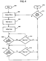
- Figure 4 is a flow chart representing the operation of the apparatus of Figure 1 under control of a microprocessor programmed to overshoot on the deflate and then inflate to the target pressure in accordance with the techniques of the invention.
- Prior art Figure 2 illustrates a pressure versus time graph illustrating a conventional cuff step deflation and measurement cycle for a conventional noninvasive blood pressure (NIBP) monitor.
- NIBP noninvasive blood pressure
- the pressure cuff 101 is inflated to a pressure above the systolic pressure, and the pressure cuff 101 is then deflated in steps of equal duration of about 8 mm Hg per step.
- a timeout duration d is provided at each step during which the signal processing circuitry searches for oscillation complexes in accordance with the techniques described in the afore-mentioned commonly assigned patents.
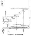
- Figure 3 is a pressure versus time graph for a blood pressure monitor modified in accordance with the principles of the invention so as to minimize the "air effect" problem which may occur in conventional blood pressure monitors.
- the pressure cuff 101 is inflated to a pressure above systolic pressure and then deflated in equal decrements of about 20 mm Hg for a rapid blood pressure determination requiring relatively few samples.
- each step deflate does not deflate the pressure cuff 101 directly to the target pressure. Instead, for each step, the pressure cuff 101 is deflated to a pressure lower than the target pressure, a short time interval w is allowed to pass, and the pressure cuff 101 is then inflated to the target pressure.
- the overall duration at each pressure step is still d (d>>w); however, the likelihood of an accurate measurement is greatly enhanced by the cancellation of the air effect. Also, the duration of w is preferably kept short to minimize the length of duration d at each pressure step.
- pressure cuff 101 is deflated at step 402 by pressure increments of a predetermined fixed magnitude, generally about 25 mm Hg per step for a desired deflation of 20 mm Hg per step, by opening deflation valve 102.
- the system waits for a short duration w (d>>w) for allowing the air effect to somewhat settle out.
- inflate valve 111 is opened to inflate pressure cuff 101 by about 5 mm Hg so that the overall step deflate is -20 mm Hg (-25 mm Hg + 5 mm Hg).
- the system then checks for oscillation complexes at the present pressure level at step 408 using conventional procedures described in the aforementioned commonly owned patents. If no oscillation complexes are detected at step 408, the system continues to check for an oscillation complex until the end of the timeout duration is reached at step 410. At this time, processing proceeds to step 416 where it is determined whether enough data has been collected to determine the patient's blood pressure. If enough data has been collected, the deflation routine is exited at step 418. However, if enough data has not been collected, steps 402-406 are repeated so that the pressure cuff 101 is again deflated 20 mm Hg to the next deflation step.
- step 408 If an oscillation complex is detected at step 408, the system then searches for a second oscillation complex at step 412 until the end of the timeout duration is reached at step 414. At this time, processing proceeds to step 416 where it is determined whether enough data has been collected to determine the patient's blood pressure. If enough data has been collected, the deflation routine is exited at step 418. However, if enough data has not been collected, steps 402-406 are repeated so that the pressure cuff 101 is again deflated 20 mm Hg to the next deflation step.
- the techniques of the invention are preferably used for large inflates and deflates of 20mm Hg or more or in the first steps after inflation where the air effects are most pronounced; however, the techniques of the invention may be used for small inflates and deflates as well, such as conventional deflates on the order of 8 mm Hg.
- the techniques of the invention may also be implemented mathematically by determining a mathematical model of the air effect, running this mathematical model concurrently with the blood pressure determination, and then arithmetically cancelling the air effect.
Landscapes
- Health & Medical Sciences (AREA)
- Life Sciences & Earth Sciences (AREA)
- Vascular Medicine (AREA)
- Cardiology (AREA)
- Biomedical Technology (AREA)
- Heart & Thoracic Surgery (AREA)
- Physiology (AREA)
- Biophysics (AREA)
- Pathology (AREA)
- Engineering & Computer Science (AREA)
- Ophthalmology & Optometry (AREA)
- Physics & Mathematics (AREA)
- Medical Informatics (AREA)
- Molecular Biology (AREA)
- Surgery (AREA)
- Animal Behavior & Ethology (AREA)
- General Health & Medical Sciences (AREA)
- Public Health (AREA)
- Veterinary Medicine (AREA)
- Measuring Pulse, Heart Rate, Blood Pressure Or Blood Flow (AREA)
Abstract
Description
- This invention relates to automated blood pressure monitoring, and more particularly, to automated blood pressure monitors that utilize a pneumatic cuff for accomplishing a sphygmomanometric measurement on a patient.
- The sphygmomanometric class of automated blood pressure monitors employs an inflatable cuff to exert controlled counter-pressure on the vasculature of a patient. One large class of such monitors, exemplified by that described in U.S. Patent Nos. 4,349,034 and 4,360,029, both to Maynard Ramsey, III and commonly assigned herewith, employs the oscillometric methodology. In accordance with the Ramsey patents, an inflatable cuff is suitably located on the limb of a patient and is pumped up to a predetermined pressure above the systolic pressure. Then, the cuff pressure is reduced in predetermined decrements, and at each level, pressure fluctuations are monitored. The resultant signals typically consist of a DC voltage with a small superimposed variational component caused by arterial blood pressure pulsations (referred to herein as "oscillation complexes" or just simply "oscillations"). After suitable filtering to reject the DC component and to provide amplification, peak pulse amplitudes (PPA) above a given base-line are measured and stored. As the decrementing continues, the peak amplitudes will normally increase from a lower level to a relative maximum, and thereafter will decrease. These peak amplitudes together form an oscillometric envelope for the patient. The lowest cuff pressure at which the oscillations have a maximum value has been found to be representative of the mean arterial pressure ("MAP"). Systolic and diastolic pressures can be derived either as predetermined fractions of MAP, or by more sophisticated methods of direct processing of the oscillation complexes.
- The step deflation technique as set forth in the Ramsey patents is the commercial standard of operation. A large percentage of clinically acceptable automated blood pressure monitors utilize the step deflation rationale. Accordingly, many subsequent developments have been directed at minimizing the duration of this step deflation period so as to minimize patient discomfort. For example, in U.S. Patent No. 4,926,873 to Frankenreiter, the size of the deflation steps for a measurement cycle is varied from measurement to measurement as a function of the patient's actual blood pressure as measured in the preceding measuring cycle. This allows the duration of the measurement cycle to be minimized since extra steps can be avoided for patients with hypertension and more accurate measurements can be made for patients with hypotension. However, the duration of each deflation step within a particular measurement cycle is not varied.
- On the other hand, in U.S. Patent Nos. 4,543,962 to Medero et al., 4,889,133 to Nelson et al., and 4,949,710 to Dorsett et al., signal processing techniques are used to minimize the duration of each deflation step within a particular measurement cycle needed for detecting and processing the oscillation complexes. Such systems typically use a fixed "timeout" period at each pressure level to search for the oscillation complexes and only advance to the next step when one or more suitable oscillation complexes are detected or the "timeout" is reached.
- Unfortunately, the entire timeout period cannot be used to search for oscillation complexes because of a problem in step deflate/inflate oscillometric blood pressure monitors known as the "air effect." The "air effect" is a slow rise or fall in cuff pressure that results from a step inflate or step inflate. The air effect occurs when a quick pressure change occurs in the cuff and the pressure cannot stabilize immediately. The air effect has many different sources, such as the thermal changes in the air in the cuff as the air pressure is changed and the material properties of the cuff fabric. Generally, the air effect interferes with the small oscillations caused by the artery beneath the cuff by causing them to have modified pulse amplitudes. As a result, after a step inflate or deflate, the oscillations cannot be detected until the next heart cycle to allow time for the air effect to settle out. If the air effect is not given time to settle out, the oscillation amplitudes may be overestimated or underestimated, thereby causing errors in the blood pressure determination.
- As the speed of analysis of the blood pressure envelope improves, larger deflate/inflate steps may be used to decrease the overall time for the blood pressure determination, thereby increasing the comfort to the patient. However, larger steps cause larger air effects which, in turn, cause longer determination times. As a result, the benefit of the larger steps are somewhat negated by the increased time needed at each step to detect the oscillation complexes.
- It is, accordingly, a primary object of the present invention to minimize "air effects" and to shorten the time needed for air effects to settle out.
- It is a further object of the present invention to prevent the underestimation or overestimation of the pulse amplitudes during an oscillometric blood pressure measurement.
- It is yet another object of the present invention to minimize errors caused by "air effects" when large deflates are used between pulse measurements.
- The above objects have been met in accordance with the present invention by providing an automated sphygmomanometer in which the air effect is substantially eliminated by deflating the pressure cuff to a pressure lower than the target pressure, waiting a short time interval, and then inflating the pressure cuff to the target pressure. Of course, this process is reversed for step inflates. The driving force that causes the air effect to settle out after a step inflate or deflate is proportional to the size of the step change in pressure and is thus greatest during the wait time before the pressure cuff is inflated or deflated to the target pressure. Once at the target pressure, the remaining air effect is counteracted by the incremental air effect introduced by the latter inflate or deflate so that the air effect settles out sooner or is completely eliminated.
- The techniques of the invention are preferably used for large inflates and deflates of 20mm Hg or more where the air effects are most pronounced; however, the techniques of the invention may be used for small inflates and deflates as well. The techniques of the invention may also be implemented mathematically by determining a mathematical model of the air effect, running this mathematical model concurrently with the blood pressure determination, and then arithmetically cancelling the air effect.
- The present invention will be better understood after reading the following detailed description of the presently preferred embodiments thereof with reference to the appended drawings, in which:
- Figure 1 is a schematic representation of a blood pressure monitor embodying the present invention.
- Figure 2 is a pressure versus time graph illustrating a measuring cycle including step deflation steps as in a conventional noninvasive blood pressure measurement system.
- Figure 3 is a pressure versus time graph illustrating a measuring cycle including deflation and inflation steps for negating the air effect in accordance with the techniques of the invention.
- Figure 4 is a flow chart representing the operation of the apparatus of Figure 1 under control of a microprocessor programmed to overshoot on the deflate and then inflate to the target pressure in accordance with the techniques of the invention.
- A system and method which meets the above-mentioned objects and provides other beneficial features in accordance with the presently preferred exemplary embodiment of the invention will be described below with reference to Figures 1-4. Those skilled in the art will readily appreciate that the description given herein with respect to those figures is for explanatory purposes only and is not intended in any way to limit the scope of the invention. Accordingly, all questions regarding the scope of the invention should be resolved by referring to the appended claims.
- In U.S. Patent No. 4,360,029, Ramsey discloses in great detail a system for oscillometric blood pressure monitoring to which the principles of the present invention may be applied with advantage. The disclosure of the Ramsey '029 patent is incorporated by reference herein. The following description of Figure 1 will act as a brief summary of the operation of that system.
- In Figure 1, the
arm 100 of a human subject is shown wearing a conventional flexible inflatable anddeflatable pressure cuff 101 for occluding the brachial artery when fully inflated. As thepressure cuff 101 is deflated usingdeflate valve 102 havingexhaust 103, the arterial occlusion is gradually relieved. As will be described more fully below, the deflation ofpressure cuff 101 viadeflate valve 102 is controlled bymicroprocessor 108 viacontrol line 104. - A
pressure transducer 105 is coupled by aduct 106 to thepressure cuff 101 for sensing the pressure therein. In accordance with conventional oscillometric techniques, pressure oscillations in the artery are sensed by changes in the counter-pressure of thepressure cuff 101, and these pressure oscillations are converted into an electrical signal bytransducer 105 and coupled overpath 107 to amicroprocessor 108 for processing. In addition, a source of pressurizedair 109 is connected via aduct 110 through an inflate valve 111 and aduct 112 to thepressure cuff 101. The inflate valve 111 is electrically controlled through aconnection 113 from themicroprocessor 108. Finally, thedeflate valve 102 is connected byduct 114 via abranch connection 115 with theduct 112 leading topressure cuff 101. - From the standpoint of the principles of the present invention, the processing of the signals from
pressure transducer 105 by themicroprocessor 108 to produce blood pressure data, and optionally to reject artifact data, can be conducted in accordance with the prior art teachings of the above-referenced Ramsey '029 and '034 patents. Alternatively, the blood pressure can be determined in accordance with the teachings of Medero et al. in U.S. Patent No. 4,543,962, of Medero in U.S. Patent No. 4,546,775, of Hood, Jr. et al. in U.S. Patent No. 4,461,266, of Ramsey, III et al. in U.S. Patent No. 4,638,810, of Ramsey, III et al. in U.S. Patent No. 4,754,761, of Ramsey, III et al. in U.S. Patent No. 5,170,795, and of Ramsey, III et al. in U.S. Patent No. 5,052,397, all of which are commonly assigned herewith and the disclosures of which are hereby incorporated by reference. In any event, it is desirable to use any of the known techniques to determine the quality of the oscillation complexes received at each level so that the blood pressure determination is made using actual blood pressure data and not artifacts. - The apparatus described above with reference to Figure 1, except for the programming of the
microprocessor 108, can be substantially the same as that disclosed in the Ramsey, III et al. '029 and '034 patents. Thus, during operation of the apparatus illustrated in Figure 1, it can be assumed that air under pressure to about 8-10 p.s.i. is available in the source ofpressurized air 109. When it is desired to initiate a determination of blood pressure, themicroprocessor 108 furnishes a signal overpath 113 to open the inflate valve 111. Thedeflate valve 102 is closed. Air from thesource 109 is communicated through inflate valve 111 andduct 112 to inflate thepressure cuff 101 to a desired level, preferably above the estimated systolic pressure of the patient.Microprocessor 108 responds to a signal onpath 107 from thepressure transducer 105, which is indicative of the instantaneous pressure in thepressure cuff 101, to interrupt the inflation of thepressure cuff 101 when the pressure in thepressure cuff 101 reaches a predetermined value above the estimated systolic pressure of the patient. Such interruption is accomplished by sending a signal overpath 113 instructing inflate valve 111 to close. Once inflate valve 111 has been closed, the blood pressure measurement can be obtained by commencing the deflate routine. - As noted above, actual measurement of the blood pressure under the control of the
microprocessor 108 and thedeflate valve 102 as sensed bypressure transducer 105 can be accomplished in any suitable manner such as that disclosed in the aforementioned patents. At the completion of each measurement cycle, thedeflate valve 102 can be reopened long enough to relax the cuff pressure substantially completely viaexhaust 103. Thereafter, thedeflate valve 102 is closed for the start of a new measurement cycle. - By way of a summation, when a blood pressure measurement is desired, the inflate valve 111 is opened while the cuff pressure is supervised by
pressure transducer 105 until the cuff pressure reaches the desired level. The inflate valve 111 is then closed. Thereafter, thedeflate valve 102 is operated usingsignal 104 frommicroprocessor 108 and the blood pressure measurement taken. To this point, the monitor operates in a conventional manner. The present invention relates to a modification of the deflation phase, and that operation will now be described with particular reference to Figures 2-4. - In typical automatic sphygmomanometric devices, the cuff deflation operation is accomplished in equal decrements, usually about 8 mm Hg per step. Prior art Figure 2 illustrates a pressure versus time graph illustrating a conventional cuff step deflation and measurement cycle for a conventional noninvasive blood pressure (NIBP) monitor. As illustrated, the
pressure cuff 101 is inflated to a pressure above the systolic pressure, and thepressure cuff 101 is then deflated in steps of equal duration of about 8 mm Hg per step. A timeout duration d is provided at each step during which the signal processing circuitry searches for oscillation complexes in accordance with the techniques described in the afore-mentioned commonly assigned patents. At the end of timeout duration d, the cuff pressure is decremented even if no oscillation complex is detected. This process of decrementing the cuff pressure and searching for oscillation complexes is repeated at least until MAP and/or the oscillation envelope may be determined. The entire blood pressure determination process is then repeated at set intervals. - As noted above, the entire timeout duration d cannot be used to search for oscillation complexes because of the "air effect" which occurs when a quick pressure change occurs in the
pressure cuff 101 and the pressure cannot stabilize immediately. Time must be allowed after a step inflate or deflate for the air effect to settle out before the oscillations may be detected. The time required for the step inflate to settle out increases as the step size increases. The operation of a step deflation/inflation technique for minimizing the air effect for a 20 mm Hg step size in accordance with the invention is illustrated in Figure 3. - Figure 3 is a pressure versus time graph for a blood pressure monitor modified in accordance with the principles of the invention so as to minimize the "air effect" problem which may occur in conventional blood pressure monitors. As illustrated in Figure 3, the
pressure cuff 101 is inflated to a pressure above systolic pressure and then deflated in equal decrements of about 20 mm Hg for a rapid blood pressure determination requiring relatively few samples. As shown, in accordance with the invention each step deflate does not deflate thepressure cuff 101 directly to the target pressure. Instead, for each step, thepressure cuff 101 is deflated to a pressure lower than the target pressure, a short time interval w is allowed to pass, and thepressure cuff 101 is then inflated to the target pressure. This process is reversed for step inflates. Since the driving force that causes the air effect to settle out after a step inflate or deflate is proportional to the size of the step change in pressure, the air effect is greatest during the wait time w before thepressure cuff 101 is inflated or deflated to the target pressure. Once at the target pressure, the remaining air effect is counteracted by the incremental air effect introduced by the latter inflate or deflate so that the air effect settles out sooner or is completely eliminated. - As shown in Figure 3, the overall duration at each pressure step is still d (d>>w); however, the likelihood of an accurate measurement is greatly enhanced by the cancellation of the air effect. Also, the duration of w is preferably kept short to minimize the length of duration d at each pressure step.
- The operation of the present invention will now be described with reference to the flow chart of Figure 4. Those skilled in the art will appreciate that the flow chart of Figure 4 is typically implemented in software on
microprocessor 108 of Figure 1 for controlling the step deflation cycle. - At the commencement of the deflation operation at
step 400,pressure cuff 101 is deflated atstep 402 by pressure increments of a predetermined fixed magnitude, generally about 25 mm Hg per step for a desired deflation of 20 mm Hg per step, by openingdeflation valve 102. Atstep 404, the system waits for a short duration w (d>>w) for allowing the air effect to somewhat settle out. Then, atstep 406, inflate valve 111 is opened to inflatepressure cuff 101 by about 5 mm Hg so that the overall step deflate is -20 mm Hg (-25 mm Hg + 5 mm Hg). The system then checks for oscillation complexes at the present pressure level atstep 408 using conventional procedures described in the aforementioned commonly owned patents. If no oscillation complexes are detected atstep 408, the system continues to check for an oscillation complex until the end of the timeout duration is reached atstep 410. At this time, processing proceeds to step 416 where it is determined whether enough data has been collected to determine the patient's blood pressure. If enough data has been collected, the deflation routine is exited atstep 418. However, if enough data has not been collected, steps 402-406 are repeated so that thepressure cuff 101 is again deflated 20 mm Hg to the next deflation step. - If an oscillation complex is detected at
step 408, the system then searches for a second oscillation complex atstep 412 until the end of the timeout duration is reached at step 414. At this time, processing proceeds to step 416 where it is determined whether enough data has been collected to determine the patient's blood pressure. If enough data has been collected, the deflation routine is exited atstep 418. However, if enough data has not been collected, steps 402-406 are repeated so that thepressure cuff 101 is again deflated 20 mm Hg to the next deflation step. - Generally, the amplitude of the two oscillation complexes detected at
steps step 416 that enough data to define the blood pressure envelope has been detected, the deflation routine is exited atstep 418 for a blood pressure determination. - The techniques of the invention are preferably used for large inflates and deflates of 20mm Hg or more or in the first steps after inflation where the air effects are most pronounced; however, the techniques of the invention may be used for small inflates and deflates as well, such as conventional deflates on the order of 8 mm Hg. The techniques of the invention may also be implemented mathematically by determining a mathematical model of the air effect, running this mathematical model concurrently with the blood pressure determination, and then arithmetically cancelling the air effect.
- It will be appreciated by those skilled in the art that the foregoing has set forth the presently preferred embodiment of the invention and an illustrative embodiment of the invention but that numerous alternative embodiments are possible without departing from the novel teachings of the invention. For example, those skilled in the art will appreciate that the techniques of the invention may be used for blood pressure monitors in which the pressure is incremented from diastolic as described, for example, in U.S. Patent No. 4,461,266 to Hood, Jr. et al. Also, those skilled in the art will appreciate that the techniques of the invention may be used for blood pressure monitors which do not use amplitude matching techniques described by Ramsey to determine whether oscillation complexes of sufficient quality have been received. In addition, those skilled in the art will appreciate that the techniques of the invention may be expanded to permit multiple, possibly somewhat random, timeout durations for the measurements at respective deflation levels. Accordingly, all such modifications are intended to be included within the scope of the appended claims.
Claims (6)
- An automated sphygmomanometer apparatus, comprising:an inflatable and deflatable pressure cuff;inflating means operatively coupled to said cuff for selectively applying a medium under pressure to said cuff for inflating and pressurizing said cuff;cuff pressure sensing means coupled to said cuff for sensing cuff pressure including any blood pressure oscillations therein;deflating means operatively coupled to said cuff for selectively relieving pressure from said cuff; andcontrol means responsive to a cuff pressure determination of said cuff pressure sensing means for controlling said inflating means to inflate said cuff and said deflating means to deflate said cuff during a blood pressure determination of a patient, said control means instructing said inflating means to inflate said cuff a predetermined amount above an estimated systolic pressure of said patient at a beginning of a blood pressure measurement cycle, instructing said deflating means to deflate said cuff to a pressure lower than a target pressure and, after a predetermined interval of time, instructing said inflating means to inflate said cuff to said target pressure for a determination of the existence and magnitude of blood pressure oscillations at said target pressure by said cuff pressure sensing means.
- An automated sphygmomanometer apparatus, comprising:an inflatable and deflatable pressure cuff;inflating means operatively coupled to said cuff for selectively applying a medium under pressure to said cuff for inflating and pressurizing said cuff;cuff pressure sensing means coupled to said cuff for sensing cuff pressure including any blood pressure oscillations therein;deflating means operatively coupled to said cuff for relieving pressure from said cuff; andcontrol means responsive to a cuff pressure determination of said cuff pressure sensing means for controlling said inflating means to inflate said cuff and said deflating means to deflate said cuff during a blood pressure determination of a patient, said control means instructing said inflating means to inflate said cuff a predetermined amount above a target pressure, and, after a predetermined interval of time, instructing said deflating means to deflate said cuff to said target pressure for a determination of the existence and magnitude of blood pressure oscillations at said target pressure by said cuff pressure sensing means, and then instructing said inflating means to inflate said cuff to a higher target pressure for a determination of the existence and magnitude of blood pressure oscillation at said higher target pressure.
- In an automatic oscillometric blood pressure monitor comprising a pressurized cuff, means for inflating and deflating said cuff, and means for measuring arterial pressure oscillation complexes through measurement of time varying pressures within said cuff, a method of measuring blood pressure of a patient comprising the steps of:(a) inflating said cuff about an artery of the patient until said cuff is at a first pressure level a predetermined amount above the patient's estimated systolic pressure;(b) deflating said cuff from said first pressure level to a second pressure level below a target pressure level;(c) after a predetermined interval of time, inflating said cuff from said second pressure level to said target pressure level; and(d) searching for arterial pressure oscillation complexes at said target pressure level.
- A method as in claim 3, comprising the further step of repeating steps (b) - (d) for subsequent pressure levels until arterial pressure oscillation complexes of a predetermined quality are detected in step (d) for a sufficient number of pressure levels to permit a blood pressure determination for the patient.
- In an automatic oscillometric blood pressure monitor comprising a pressurized cuff, means for inflating and deflating said cuff, and means for measuring arterial pressure oscillation complexes through measurement of time varying pressures within said cuff, a method of measuring blood pressure of a patient comprising the steps of:(a) inflating said cuff about an artery of the patient until said cuff is at a first pressure level a predetermined amount above a target pressure level;(b) after a predetermined interval of time, deflating said cuff from said first pressure level to said target pressure level; and(c) searching for arterial pressure oscillation complexes at said target pressure level.
- A method as in claim 5, comprising the further step of repeating steps (a) - (c) for higher target pressure levels until arterial pressure oscillation complexes of a predetermined quality are detected in step (c) for a sufficient number of pressure levels to permit a blood pressure determination for the patient.
Applications Claiming Priority (2)
| Application Number | Priority Date | Filing Date | Title |
|---|---|---|---|
| US08/372,137 US5579776A (en) | 1995-01-13 | 1995-01-13 | Oscillometric blood pressure monitor with enhanced cuff pressure control |
| US372137 | 1995-01-13 |
Publications (3)
| Publication Number | Publication Date |
|---|---|
| EP0723761A2 true EP0723761A2 (en) | 1996-07-31 |
| EP0723761A3 EP0723761A3 (en) | 1998-06-24 |
| EP0723761B1 EP0723761B1 (en) | 2004-04-28 |
Family
ID=23466857
Family Applications (1)
| Application Number | Title | Priority Date | Filing Date |
|---|---|---|---|
| EP96300241A Expired - Lifetime EP0723761B1 (en) | 1995-01-13 | 1996-01-12 | Oscillometric blood pressure monitor with enhanced cuff pressure control |
Country Status (7)
| Country | Link |
|---|---|
| US (1) | US5579776A (en) |
| EP (1) | EP0723761B1 (en) |
| JP (1) | JP3738075B2 (en) |
| AU (1) | AU692963B2 (en) |
| CA (1) | CA2167010C (en) |
| DE (1) | DE69632278T2 (en) |
| ZA (1) | ZA96263B (en) |
Families Citing this family (27)
| Publication number | Priority date | Publication date | Assignee | Title |
|---|---|---|---|---|
| DE69416475T2 (en) * | 1993-04-02 | 1999-07-22 | Nagano, Ken, Nagano, Nagano | ELECTRONIC INSTRUMENT FOR MEASURING BLOOD PRESSURE |
| US6050951A (en) * | 1997-11-10 | 2000-04-18 | Critikon Company, L.L.C. | NIBP trigger in response to detected heart rate variability |
| US6358213B1 (en) | 1999-08-18 | 2002-03-19 | Critikon Company, Llc | Calculation of quality and its use in determination of indirect noninvasive blood pressure |
| DE10055316A1 (en) * | 2000-11-08 | 2002-05-16 | Taidoc Corp | Method and device for determining patient blood pressure by generation of two blood pressure curves and a corresponding envelope curve such that patient discomfort is prevented and excessive pressure application is not required |
| KR100745747B1 (en) | 2001-08-21 | 2007-08-02 | 삼성전자주식회사 | Apparatus and method for measuring blood-pressure using air-pressure capable of being linearly varied thereby |
| US20030144829A1 (en) * | 2002-01-25 | 2003-07-31 | Geatz Michael W. | System and method for sensing and evaluating physiological parameters and modeling an adaptable predictive analysis for symptoms management |
| US6893403B2 (en) * | 2003-02-25 | 2005-05-17 | Ge Medical Systems Information Technologies, Inc. | Oscillometric determination of blood pressure |
| US7186218B2 (en) * | 2003-02-27 | 2007-03-06 | Ge Medical Systems Information Technologies Inc. | Method and system for cuff pressure reversions |
| US7070566B2 (en) | 2003-03-13 | 2006-07-04 | Ge Medical Systems Information Technologies, Inc. | Artifact rejection using pulse quality values |
| US7198604B2 (en) * | 2003-03-18 | 2007-04-03 | Ge Medical Systems Information Technologies | Method and system for determination of pulse rate |
| US7074192B2 (en) * | 2003-07-03 | 2006-07-11 | Ge Medical Systems Information Technologies, Inc. | Method and apparatus for measuring blood pressure using relaxed matching criteria |
| US7288070B2 (en) * | 2004-05-18 | 2007-10-30 | The General Electric Company | Method and apparatus for determining extreme blood pressure values |
| US7214192B2 (en) * | 2004-09-07 | 2007-05-08 | Biomedix, Inc. | Vascular testing system |
| US7172555B2 (en) * | 2004-09-07 | 2007-02-06 | Biomedix, Inc. | Vascular testing system |
| US7166076B2 (en) * | 2004-09-07 | 2007-01-23 | Biomedix, Inc. | Vascular testing system |
| US7678059B2 (en) * | 2005-10-12 | 2010-03-16 | General Electric Company | Non-invasive blood pressure monitor with improved performance |
| US7390302B2 (en) * | 2006-08-16 | 2008-06-24 | The General Electric Company | Method and system of determining NIBP target inflation pressure using an SpO2 plethysmograph signal |
| US7462152B2 (en) * | 2006-09-07 | 2008-12-09 | The General Electric Company | Method and system utilizing SpO2 plethysmograph signal to reduce NIBP determination time |
| US7300404B1 (en) | 2006-09-07 | 2007-11-27 | The General Electric Company | Method and system utilizing SpO2 plethysmograph signal to qualify NIBP pulses |
| US7927283B2 (en) * | 2007-03-20 | 2011-04-19 | Tiba Medical, Inc. | Blood pressure algorithm |
| US8211030B2 (en) * | 2009-03-26 | 2012-07-03 | The General Electric Company | NIBP target inflation pressure automation using derived SPO2 signals |
| US8721557B2 (en) * | 2011-02-18 | 2014-05-13 | Covidien Lp | Pattern of cuff inflation and deflation for non-invasive blood pressure measurement |
| US10945612B2 (en) * | 2014-04-03 | 2021-03-16 | The Regents Of The University Of California | Assessing endothelial function using a blood pressure cuff |
| US10048703B1 (en) * | 2014-06-06 | 2018-08-14 | The United States Of America As Represented By The Secretary Of The Navy | Force feedback pressure cuff systems and methods |
| EP3334336B1 (en) | 2015-08-14 | 2024-01-17 | The Regents of The University of California | Assessing endothelial function and providing calibrated ufmd data using a blood pressure cuff |
| US10772571B2 (en) | 2016-11-15 | 2020-09-15 | Welch Allyn, Inc. | Method and systems for correcting for arterial compliance in a blood pressure assessment |
| KR20200097803A (en) | 2017-12-22 | 2020-08-19 | 센시프리 리미티드 | Continuous blood pressure measurement |
Citations (3)
| Publication number | Priority date | Publication date | Assignee | Title |
|---|---|---|---|---|
| US4349034A (en) * | 1978-04-10 | 1982-09-14 | Johnson & Johnson | Automatic mean blood pressure reading device |
| US5000187A (en) * | 1986-08-11 | 1991-03-19 | Colin Electronics Co., Ltd. | Blood pressure measuring apparatus |
| DE4331451C1 (en) * | 1993-09-16 | 1994-11-17 | Hewlett Packard Gmbh | Blood pressure instrument and method of controlling the cuff pressure in a blood pressure instrument |
Family Cites Families (19)
| Publication number | Priority date | Publication date | Assignee | Title |
|---|---|---|---|---|
| US4360029A (en) * | 1978-04-10 | 1982-11-23 | Johnson & Johnson | Automatic mean blood pressure reading device |
| US4461266A (en) * | 1982-04-29 | 1984-07-24 | Critikon, Inc. | Adaptive incremental blood pressure monitor |
| US4546775A (en) * | 1984-06-18 | 1985-10-15 | Critikon, Inc. | Detection of blood pressure complexes in automated vital signs monitors |
| US4543962A (en) * | 1984-07-09 | 1985-10-01 | Critikon, Inc. | Method of automated blood pressure detection |
| US5052397A (en) * | 1985-07-05 | 1991-10-01 | Critikon, Inc. | Oscillometric blood pressure monitor employing non-uniform pressure decrementing steps |
| US5170795A (en) * | 1985-07-05 | 1992-12-15 | Critikon, Inc. | Oscillometric blood pressure monitor and method employing non-uniform pressure decrementing steps |
| US4754761A (en) * | 1985-07-05 | 1988-07-05 | Critikon, Inc. | Automated mean arterial blood pressure monitor with data enhancement |
| US4638810A (en) * | 1985-07-05 | 1987-01-27 | Critikon, Inc. | Automated diastolic blood pressure monitor with data enhancement |
| US4627440A (en) * | 1985-07-05 | 1986-12-09 | Critikon, Inc. | Sphygmomanometric cuff pressurizing system |
| US4774960A (en) * | 1986-10-30 | 1988-10-04 | Datascope Corporation | Method and apparatus for measuring blood pressure |
| US4889133A (en) * | 1988-05-25 | 1989-12-26 | Protocol Systems, Inc. | Method for noninvasive blood-pressure measurement by evaluation of waveform-specific area data |
| EP0353315B1 (en) * | 1988-08-01 | 1993-10-13 | Hewlett-Packard GmbH | Method for measuring blood pressure and apparatus for automated blood pressure measuring |
| US4949710A (en) * | 1988-10-06 | 1990-08-21 | Protocol Systems, Inc. | Method of artifact rejection for noninvasive blood-pressure measurement by prediction and adjustment of blood-pressure data |
| US4984577A (en) * | 1989-03-20 | 1991-01-15 | Hewlett-Packard Company | Oscillometric non-invasive method for measuring blood pressure and apparatus for automated oscillometric blood pressure measuring |
| US5054495A (en) * | 1989-07-10 | 1991-10-08 | Colin Electronics Co., Ltd. | Automatic blood-pressure measuring apparatus |
| US5103833A (en) * | 1989-12-20 | 1992-04-14 | Critikon, Inc. | Peripheral arterial monitoring instruments |
| US5261413A (en) * | 1990-08-02 | 1993-11-16 | Colin Electronics Co., Ltd. | Blood pressure measure system |
| US5253648A (en) * | 1991-10-11 | 1993-10-19 | Spacelabs Medical, Inc. | Method and apparatus for excluding artifacts from automatic blood pressure measurements |
| US5280790A (en) * | 1993-01-25 | 1994-01-25 | Spacelabs Medical, Inc. | Automatic blood pressure monitor having reduced data loss sensitivity to cuff pressure changes |
-
1995
- 1995-01-13 US US08/372,137 patent/US5579776A/en not_active Expired - Lifetime
-
1996
- 1996-01-09 AU AU40889/96A patent/AU692963B2/en not_active Ceased
- 1996-01-11 CA CA002167010A patent/CA2167010C/en not_active Expired - Fee Related
- 1996-01-12 JP JP02064196A patent/JP3738075B2/en not_active Expired - Fee Related
- 1996-01-12 DE DE69632278T patent/DE69632278T2/en not_active Expired - Fee Related
- 1996-01-12 ZA ZA96263A patent/ZA96263B/en unknown
- 1996-01-12 EP EP96300241A patent/EP0723761B1/en not_active Expired - Lifetime
Patent Citations (3)
| Publication number | Priority date | Publication date | Assignee | Title |
|---|---|---|---|---|
| US4349034A (en) * | 1978-04-10 | 1982-09-14 | Johnson & Johnson | Automatic mean blood pressure reading device |
| US5000187A (en) * | 1986-08-11 | 1991-03-19 | Colin Electronics Co., Ltd. | Blood pressure measuring apparatus |
| DE4331451C1 (en) * | 1993-09-16 | 1994-11-17 | Hewlett Packard Gmbh | Blood pressure instrument and method of controlling the cuff pressure in a blood pressure instrument |
Also Published As
| Publication number | Publication date |
|---|---|
| AU4088996A (en) | 1996-07-25 |
| ZA96263B (en) | 1997-07-14 |
| EP0723761A3 (en) | 1998-06-24 |
| JPH08308808A (en) | 1996-11-26 |
| DE69632278T2 (en) | 2005-06-02 |
| US5579776A (en) | 1996-12-03 |
| EP0723761B1 (en) | 2004-04-28 |
| CA2167010A1 (en) | 1996-07-14 |
| CA2167010C (en) | 2007-06-12 |
| DE69632278D1 (en) | 2004-06-03 |
| JP3738075B2 (en) | 2006-01-25 |
| AU692963B2 (en) | 1998-06-18 |
Similar Documents
| Publication | Publication Date | Title |
|---|---|---|
| US5579776A (en) | Oscillometric blood pressure monitor with enhanced cuff pressure control | |
| US5606977A (en) | Oscillometric blood pressure monitor which automatically determines when to take blood pressure measurements | |
| US5577508A (en) | Determination of oscillometric blood pressure by linear approximation | |
| US5651370A (en) | Detection of oscillometeric blood pressure complexes using correlation | |
| US6767328B2 (en) | Method and apparatus for determining blood pressure using pressure pulse duty cycle | |
| US7390302B2 (en) | Method and system of determining NIBP target inflation pressure using an SpO2 plethysmograph signal | |
| US5052397A (en) | Oscillometric blood pressure monitor employing non-uniform pressure decrementing steps | |
| US7300404B1 (en) | Method and system utilizing SpO2 plethysmograph signal to qualify NIBP pulses | |
| US7462152B2 (en) | Method and system utilizing SpO2 plethysmograph signal to reduce NIBP determination time | |
| US5791348A (en) | Automatic blood pressure measuring system | |
| US7153269B1 (en) | Method and system for estimation of blood pressure during cuff inflation | |
| US4984577A (en) | Oscillometric non-invasive method for measuring blood pressure and apparatus for automated oscillometric blood pressure measuring | |
| US8211030B2 (en) | NIBP target inflation pressure automation using derived SPO2 signals | |
| EP1195133A2 (en) | Oscillometric blood pressure monitor with improved perfomance in the presence of arrhythmias | |
| US7226421B1 (en) | Method of controlling blood pressure cuff deflation | |
| EP0353315A1 (en) | Method for measuring blood pressure and apparatus for automated blood pressure measuring | |
| JPH0512933B2 (en) | ||
| EP0208520B1 (en) | Oscillometric blood pressure monitor employing non uniform pressure decrementing steps | |
| EP0353316B1 (en) | Method for measuring blood pressure and apparatus for automated blood pressure measuring | |
| US5518000A (en) | Oscillometric blood pressure monitor employing deflation periods of alternating durations | |
| US6475154B1 (en) | Method and apparatus for non-invasive blood-pressure measurement | |
| US6458085B1 (en) | Method and apparatus for oscillometric blood-pressure measurement | |
| US5993396A (en) | Method and apparatus for determining a minimum wait time between blood pressure determinations |
Legal Events
| Date | Code | Title | Description |
|---|---|---|---|
| PUAI | Public reference made under article 153(3) epc to a published international application that has entered the european phase |
Free format text: ORIGINAL CODE: 0009012 |
|
| AK | Designated contracting states |
Kind code of ref document: A2 Designated state(s): DE ES FR GB IT PT SE |
|
| PUAL | Search report despatched |
Free format text: ORIGINAL CODE: 0009013 |
|
| AK | Designated contracting states |
Kind code of ref document: A3 Designated state(s): DE ES FR GB IT PT SE |
|
| 17P | Request for examination filed |
Effective date: 19981126 |
|
| RAP1 | Party data changed (applicant data changed or rights of an application transferred) |
Owner name: CRITIKON COMPANY, L.L.C. |
|
| 17Q | First examination report despatched |
Effective date: 20021023 |
|
| GRAP | Despatch of communication of intention to grant a patent |
Free format text: ORIGINAL CODE: EPIDOSNIGR1 |
|
| GRAS | Grant fee paid |
Free format text: ORIGINAL CODE: EPIDOSNIGR3 |
|
| GRAA | (expected) grant |
Free format text: ORIGINAL CODE: 0009210 |
|
| AK | Designated contracting states |
Kind code of ref document: B1 Designated state(s): DE ES FR GB IT PT SE |
|
| PG25 | Lapsed in a contracting state [announced via postgrant information from national office to epo] |
Ref country code: IT Free format text: LAPSE BECAUSE OF FAILURE TO SUBMIT A TRANSLATION OF THE DESCRIPTION OR TO PAY THE FEE WITHIN THE PRE;WARNING: LAPSES OF ITALIAN PATENTS WITH EFFECTIVE DATE BEFORE 2007 MAY HAVE OCCURRED AT ANY TIME BEFORE 2007. THE CORRECT EFFECTIVE DATE MAY BE DIFFERENT FROM THE ONE RECORDED.SCRIBED TIME-LIMIT Effective date: 20040428 Ref country code: FR Free format text: LAPSE BECAUSE OF FAILURE TO SUBMIT A TRANSLATION OF THE DESCRIPTION OR TO PAY THE FEE WITHIN THE PRESCRIBED TIME-LIMIT Effective date: 20040428 |
|
| REG | Reference to a national code |
Ref country code: GB Ref legal event code: FG4D |
|
| REF | Corresponds to: |
Ref document number: 69632278 Country of ref document: DE Date of ref document: 20040603 Kind code of ref document: P |
|
| PG25 | Lapsed in a contracting state [announced via postgrant information from national office to epo] |
Ref country code: SE Free format text: LAPSE BECAUSE OF FAILURE TO SUBMIT A TRANSLATION OF THE DESCRIPTION OR TO PAY THE FEE WITHIN THE PRESCRIBED TIME-LIMIT Effective date: 20040728 |
|
| PG25 | Lapsed in a contracting state [announced via postgrant information from national office to epo] |
Ref country code: ES Free format text: LAPSE BECAUSE OF FAILURE TO SUBMIT A TRANSLATION OF THE DESCRIPTION OR TO PAY THE FEE WITHIN THE PRESCRIBED TIME-LIMIT Effective date: 20040808 |
|
| PGFP | Annual fee paid to national office [announced via postgrant information from national office to epo] |
Ref country code: FR Payment date: 20050117 Year of fee payment: 10 |
|
| PLBE | No opposition filed within time limit |
Free format text: ORIGINAL CODE: 0009261 |
|
| STAA | Information on the status of an ep patent application or granted ep patent |
Free format text: STATUS: NO OPPOSITION FILED WITHIN TIME LIMIT |
|
| EN | Fr: translation not filed | ||
| 26N | No opposition filed |
Effective date: 20050131 |
|
| PG25 | Lapsed in a contracting state [announced via postgrant information from national office to epo] |
Ref country code: PT Free format text: LAPSE BECAUSE OF NON-PAYMENT OF DUE FEES Effective date: 20040928 |
|
| PGFP | Annual fee paid to national office [announced via postgrant information from national office to epo] |
Ref country code: DE Payment date: 20080229 Year of fee payment: 13 |
|
| PG25 | Lapsed in a contracting state [announced via postgrant information from national office to epo] |
Ref country code: DE Free format text: LAPSE BECAUSE OF NON-PAYMENT OF DUE FEES Effective date: 20090801 |
|
| PGFP | Annual fee paid to national office [announced via postgrant information from national office to epo] |
Ref country code: GB Payment date: 20150127 Year of fee payment: 20 |
|
| REG | Reference to a national code |
Ref country code: GB Ref legal event code: PE20 Expiry date: 20160111 |
|
| PG25 | Lapsed in a contracting state [announced via postgrant information from national office to epo] |
Ref country code: GB Free format text: LAPSE BECAUSE OF EXPIRATION OF PROTECTION Effective date: 20160111 |