EP0723485B1 - Pfosten, latten und zubehör dafür - Google Patents
Pfosten, latten und zubehör dafür Download PDFInfo
- Publication number
- EP0723485B1 EP0723485B1 EP94931222A EP94931222A EP0723485B1 EP 0723485 B1 EP0723485 B1 EP 0723485B1 EP 94931222 A EP94931222 A EP 94931222A EP 94931222 A EP94931222 A EP 94931222A EP 0723485 B1 EP0723485 B1 EP 0723485B1
- Authority
- EP
- European Patent Office
- Prior art keywords
- post
- prong
- staple
- posts
- face
- Prior art date
- Legal status (The legal status is an assumption and is not a legal conclusion. Google has not performed a legal analysis and makes no representation as to the accuracy of the status listed.)
- Expired - Lifetime
Links
- 238000000034 method Methods 0.000 claims description 4
- 230000000295 complement effect Effects 0.000 claims description 2
- 238000004519 manufacturing process Methods 0.000 claims description 2
- 238000007493 shaping process Methods 0.000 claims description 2
- 239000002184 metal Substances 0.000 description 10
- 229910052751 metal Inorganic materials 0.000 description 10
- 239000000463 material Substances 0.000 description 2
- 238000007792 addition Methods 0.000 description 1
- 238000005452 bending Methods 0.000 description 1
- 238000010276 construction Methods 0.000 description 1
- 238000010586 diagram Methods 0.000 description 1
- 238000009434 installation Methods 0.000 description 1
- 150000002739 metals Chemical class 0.000 description 1
- 238000012986 modification Methods 0.000 description 1
- 230000004048 modification Effects 0.000 description 1
Images


Classifications
-
- E—FIXED CONSTRUCTIONS
- E04—BUILDING
- E04H—BUILDINGS OR LIKE STRUCTURES FOR PARTICULAR PURPOSES; SWIMMING OR SPLASH BATHS OR POOLS; MASTS; FENCING; TENTS OR CANOPIES, IN GENERAL
- E04H17/00—Fencing, e.g. fences, enclosures, corrals
- E04H17/02—Wire fencing, e.g. made of wire mesh
- E04H17/10—Wire fencing, e.g. made of wire mesh characterised by the way of connecting wire to posts; Droppers
- E04H17/124—Wire fencing, e.g. made of wire mesh characterised by the way of connecting wire to posts; Droppers connecting by one or more clamps, clips, screws, wedges or ties
-
- B—PERFORMING OPERATIONS; TRANSPORTING
- B25—HAND TOOLS; PORTABLE POWER-DRIVEN TOOLS; MANIPULATORS
- B25D—PERCUSSIVE TOOLS
- B25D1/00—Hand hammers; Hammer heads of special shape or materials
- B25D1/16—Hand hammers; Hammer heads of special shape or materials having the impacting head in the form of a sleeve slidable on a shaft, e.g. hammers for driving a valve or draw-off tube into a barrel
-
- F—MECHANICAL ENGINEERING; LIGHTING; HEATING; WEAPONS; BLASTING
- F16—ENGINEERING ELEMENTS AND UNITS; GENERAL MEASURES FOR PRODUCING AND MAINTAINING EFFECTIVE FUNCTIONING OF MACHINES OR INSTALLATIONS; THERMAL INSULATION IN GENERAL
- F16G—BELTS, CABLES, OR ROPES, PREDOMINANTLY USED FOR DRIVING PURPOSES; CHAINS; FITTINGS PREDOMINANTLY USED THEREFOR
- F16G11/00—Means for fastening cables or ropes to one another or to other objects; Caps or sleeves for fixing on cables or ropes
Definitions
- This invention relates to posts, battens and the like which have a number of uses, one example being the construction of permanent or semi-permanent fencing.
- New Zealand Patent No.s 212487, 214830 and 217784 describe elements of a fencing system based on a metal post.
- the fencing system has been sold in New Zealand and elsewhere under the name STAPLELOKTM, and has substantial advantages when compared with conventional (timber and metal) post and batten fences.
- the STAPLELOK system provides ease of handling, it is fast to erect, versatile and flexible.
- One object of the present invention to provide improvements to metal fencing systems which will increase the versatility and strength of the systems and which will address the above-mentioned needs.
- an elongate post of substantially rectilinear body having, on a substantially flat face, an open channel having two parallel channel sides defined by adjacent inwardly turned edges to which attachments can be made, characterised in that the channel sides having opposed serrated faces, each channel side terminating at an inner end, said opposed serrated faces co-operating to provide a series of aligned apertures with respect to which attachments can be secured.
- the serrated edges can be regular and of a generally saw-tooth configuration with the tips of each coincident.
- the inner faces of the inwardly turned edges at the widest point can be provided with a surface which is substantially parallel with the said face.
- Posts as aforesaid can be used to support a series of spaced fence wires, the fence wires being secured to the posts by staples driven into the openings of the posts.
- the staples can be two-pronged staples each prong being joined by a common limb and each staple engaging with a separate part of the opening of said face.
- the locating face of said inner edges can be co-planar with the ridge of the spike of each staple prong.
- the post can be secured to a structure to support a wall lining or such like of a building.
- a method of manufacturing a post comprising the steps of feeding an elongate plate to a roll-forming apparatus, serrating side edges of the elongate plate and shaping the plate into a box-section.
- the side edges can be shaped prior to being serrated.
- the serration can be achieved by a pair or pairs of complimentary toothed wheels.
- a fence comprising a plurality of elongate posts as defined in claim 1.
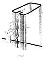
- a simple horizontal wire fence comprises posts generally indicated by arrow 1, intermediate battens generally indicated by arrow 2, and a plurality of horizontal fence wires 3.
- the posts 1 are driven into the ground and the battens 2 span the fence wires from top to bottom.
- the fence is erected by driving the required number of posts 1 into the ground securing wires 3 to the posts using staples or other means, tensioning the wires and then fixing the battens 2 at desired intervals.
- a post 1 in accordance with the present invention has a substantially rectilinear body 4 having a front face 5 with an opening generally indicated by arrow 6 therein.
- Opposite faces of the body 4 may be of complementary equal or unequal lengths.
- Each post may be provided with a cap (not shown) which protects the tip of the post against impact.
- the body 4 is constructed in metals as aforesaid although other materials may be suitable.
- the opening 6 is defined by two inwardly turned free edges 7 which are serrated such that tips of the free edges meet or nearly meet at 8 at intervals with sockets 9 being provided between.
- the front face 5 thus presents a series of sockets 9 to which fasteners or other attachment means can be secured.
- New Zealand STAPLELOKTM patents previously referred to describe how a staple can be driven into a channel between flanges of posts to secure wires or other attachments to the posts.
- the opening 6 of the post of the present invention also facilitates the attachment of staples and other accessories in a somewhat similar manner with the important exception that the opening 6 is an open channel and the arrangement of the present invention prevents longitudinal movement of the staple (movement in a vertical plane when a fence is erected). It is noted that the inner-most parts 10 of the edges 7 are substantially parallel to the front face of the post, and that the sockets 9 are wider than they are deep.
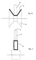
- the staple illustrated ( Figures 5 and 6) has arms generally indicated by arrow 11 which are generally spear-shaped having a tip part 12, divergent sides 13 which lead to a shoulder 14 where the arm narrows to be a predetermined width W larger than the width WO of the sockets 9 in the front face 5 of the post 1.
- the post 1 can be formed by roll-forming from a flat sheet of material with rollers gradually making each bend in the body of the post and forming the serrated free edges 7. At the end of the roll-forming process the closed edges 7 are near contact at intervals discussed.
- the post described is considered to have the significant advantages of being more robust than its predecessors and whilst maintaining all of the previous advantages, the serrated face allows staples and attachments to be securely fixed and the post configuration provides resistance to torsional and other bending forces which may be imposed on it.
- posts described may be useful in other applications, for example as studs and noggings to support wall/ceiling boards or for providing protection and support for ducting, suspended ceilings, pipes, electrical wires.
- the post of the present invention can be formed by roll-forming apparatus.
- the roll-forming apparatus is not shown in full in the line drawings but supports and rollers are shown in broken outline.
- a metal plate 16 is progressively formed into the post previously described.
- the plate 16 passes between complimentary rollers 21, 22 which have toothed ends 23 and the edges 18 are serrated.
- the metal plate is formed into the box-shape indicated by rollers 24, 25, intermediate rollers (not shown) and at the finishing point roller 26 which has a thin central fin 27 centralises the metal section.
Landscapes
- Engineering & Computer Science (AREA)
- Mechanical Engineering (AREA)
- General Engineering & Computer Science (AREA)
- Architecture (AREA)
- Civil Engineering (AREA)
- Structural Engineering (AREA)
- Fencing (AREA)
- Discharge Heating (AREA)
- Supports Or Holders For Household Use (AREA)
- Stringed Musical Instruments (AREA)
- Toys (AREA)
- Purses, Travelling Bags, Baskets, Or Suitcases (AREA)
- Mirrors, Picture Frames, Photograph Stands, And Related Fastening Devices (AREA)
- Golf Clubs (AREA)
- Acyclic And Carbocyclic Compounds In Medicinal Compositions (AREA)
Claims (9)
- Länglicher Pfosten (1) mit im wesentlichen geradlinigem Körper (4), der auf einer im wesentlichen ebenen Fläche (5) einen offenen Kanal (6) besitzt, welcher zwei durch benachbarte, nach innen gewendete Kanten (7) definierte, parallele Rinnenseiten aufweist, an denen Halterungen befestigt werden können, dadurch gekennzeichnet, daß die Rinnenseiten einander gegenüberliegende gezahnte Fronten aufweisen, wobei jede Rinnenseite an einem inneren Ende (10) aufhört und die einander gegenüberliegenden gezahnten Fronten derart zusammenwirken, daß sie eine Reihe von ausgerichteten Öffnungen (9) bilden, unter deren Einbeziehung Halterungen befestigt werden können.
- Länglicher Pfosten nach Anspruch 1, bei dem sich Zähne über die gesamte Länge jeder der einander gegenüberliegenden Fronten erstrecken.
- Länglicher Pfosten nach Anspruch 1 oder 2, worin die Zähne von im allgemeinen sägezahnförmiger Gestalt sind, wobei jeder Zahn eine scharfe, spitz zulaufende Spitze (8) besitzt, die auf die Spitze (8) eines Zahns in der gegenüberliegenden Front trifft.
- Zaun, umfassend:wobei jede Klammer einen ersten Zinken (11) und einen zweiten Zinken (11) aufweist, wobei jeder Zinken über ein Verbindungsglied mit dem anderen Zinken verbunden ist und der erste Klammerzinken einer entsprechenden Klammer in eine erste des genannten Paares benachbarter Öffnungen (9) der Front (5) des Pfostens (1) eingreift und der zweite Klammerzinken in die andere Öffnung (9) der genannten benachbarten Öffnungen eingreift;eine Mehrzahl länglicher Pfosten (1) wie in Anspruch 1 beansprucht;eine Reihe von beabstandeten Zaundrähten (3), die von den Pfosten gehalten werden;eine Mehrzahl von Klammern, die die Zaundrähte (3) an den Pfosten (1) halten, wobei jede Klammer in ein Paar von benachbarten Öffnungen (9) ihres entsprechenden Pfostens eingeführt wird, um die Zaundrähte an den Pfosten zu befestigen;
wobei jede Rinnenseite (7) des Pfostens (1) eine örtlich festgelegte Endfläche (10) am inneren Ende der genannten Rinnenseite (7) besitzt, wobei die örtlich festgelegten Endflächen (10) zueinander koplanar und zu den genannten Rinnenseiten (7) rechtwinklig stehen; und
wobei jede Klammer eine Schulter (14) besitzt, wobei die örtlich festgelegten Endflächen (10) der genannten Rinnenseiten (7) koplanar und über ihre Länge hinweg im Eingriff mit der Schulter (14) jeder eingeführten Klammernzinke (11) sind. - Zaun nach Anspruch 4, worin jede Klammerzinke (11) allgemein flach ausgebildet ist und sich parallel zur anderen Klammerzinke und im rechten Winkel zum Verbindungsglied erstreckt, wobei jede Zinke (11) im wesentlichen pfeilförmig ausgebildet ist und ein äußeres Ende mit einer einzigen, scharfen Spitze (12), sich verjüngende Seitenflanken (13), die sich vom äußeren Ende zur genannten Schulter (14) erstrecken, wobei die sich verjüngenden Seitenflanken (13) an der genannten Schulter ihre größte Breite aufweisen, die größer ist als die Breite der genannten Öffnung (9), und ein Endstück mit verringerter Breite besitzen, das sich von der genannten Schulter (14) zu dem genannten Verbindungsstück erstreckt, wobei das Endstück mit der verringerten Breite parallele Seitenränder besitzt, die an den entsprechenden parallelen Rinnenseiten (7) anliegen.
- Pfosten (1) oder Mehrzahl von Pfosten nach einem der Ansprüche 1 bis 3 in Befestigung an eine Struktur zum Halten einer Wandauskleidung oder derartigem eines Gebäudes.
- Verfahren zum Herstellen eines Pfostens (1) oder einer Mehrzahl von Pfosten nach einem der Ansprüche 1 bis 3, umfassend die Schritte:Einführen einer länglichen Platte (16) in eine Profilwalzenvorrichtung;Ausbilden von sägezahnförmigen Seitenrändern (7) der länglichen Platte (16) undÜberführen der länglichen Platte (16) in einen im wesentlichen geradlinigen Querschnitt (4).
- Verfahren nach Anspruch 7, worin die genannten Seitenränder (18) nach innen umgebogen werden, bevor sie gezahnt werden.
- Verfahren nach Anspruch 7 oder 8, worin die Zähnung mit Hilfe eines Paars oder von Paaren komplementärer gezähnter Räder (21, 22) bewirkt wird.
Applications Claiming Priority (3)
| Application Number | Priority Date | Filing Date | Title |
|---|---|---|---|
| NZ248964A NZ248964A (en) | 1993-10-15 | 1993-10-15 | Fencing posts, fences, post drivers; post member has on one face an opening having opposed inwardly turned edges |
| NZ24896493 | 1993-10-15 | ||
| PCT/NZ1994/000108 WO1995010372A1 (en) | 1993-10-15 | 1994-10-14 | Posts, battens and accessories therefor |
Publications (3)
| Publication Number | Publication Date |
|---|---|
| EP0723485A1 EP0723485A1 (de) | 1996-07-31 |
| EP0723485A4 EP0723485A4 (de) | 1997-01-22 |
| EP0723485B1 true EP0723485B1 (de) | 2002-06-12 |
Family
ID=19924529
Family Applications (1)
| Application Number | Title | Priority Date | Filing Date |
|---|---|---|---|
| EP94931222A Expired - Lifetime EP0723485B1 (de) | 1993-10-15 | 1994-10-14 | Pfosten, latten und zubehör dafür |
Country Status (10)
| Country | Link |
|---|---|
| US (1) | US5921530A (de) |
| EP (1) | EP0723485B1 (de) |
| AT (1) | ATE218936T1 (de) |
| AU (1) | AU690590B2 (de) |
| CA (1) | CA2174086A1 (de) |
| CZ (1) | CZ284811B6 (de) |
| DE (1) | DE69430809D1 (de) |
| NZ (1) | NZ248964A (de) |
| WO (1) | WO1995010372A1 (de) |
| ZA (1) | ZA948138B (de) |
Families Citing this family (13)
| Publication number | Priority date | Publication date | Assignee | Title |
|---|---|---|---|---|
| SG75798A1 (en) * | 1996-06-22 | 2000-10-24 | Aluminium Structure Pte Ltd | A fencing system |
| CN100395049C (zh) * | 2002-11-29 | 2008-06-18 | 北新建材(集团)有限公司 | 塑钢门窗五金件中c形件的制造方法 |
| US7188380B1 (en) * | 2006-03-27 | 2007-03-13 | Hao-Jen Wang | Fabricated bedstead member |
| US7789376B2 (en) * | 2006-05-26 | 2010-09-07 | Allied Tube & Conduit Corporation | Fencing construction apparatus and method |
| US7832497B2 (en) * | 2007-10-04 | 2010-11-16 | Robert Wilson | Shock dampening post driver |
| US7980323B2 (en) * | 2007-10-04 | 2011-07-19 | Robert Wilson | Shock dampening post driver |
| US20090258127A1 (en) * | 2008-04-15 | 2009-10-15 | Joshua Holtz | Container Rack of a Food Warmer and Method of Use |
| US20110031356A1 (en) * | 2009-08-06 | 2011-02-10 | Vonada Lowell L | Fastener |
| ES2374487B1 (es) * | 2011-12-12 | 2012-12-21 | Procoard, S.L. | Dispositivo de anclaje para un cerramiento metálico y cerramiento correspondiente |
| US8973904B2 (en) | 2013-03-12 | 2015-03-10 | William P McCann | Fence assembly |
| CN104234506B (zh) * | 2014-09-18 | 2017-04-05 | 张家港固耐特围栏系统有限公司 | 一种压力报警装置限位卡 |
| GB2541960B (en) * | 2016-01-19 | 2018-02-21 | Hampton Steel Ltd | Fencing system |
| US11692571B2 (en) * | 2019-04-08 | 2023-07-04 | Volvo Car Corporation | Clip assembly for holding a component during a vehicle assembly/disassembly process |
Family Cites Families (29)
| Publication number | Priority date | Publication date | Assignee | Title |
|---|---|---|---|---|
| US803706A (en) * | 1904-08-10 | 1905-11-07 | Henry Mcmaster | Cement-post fastening. |
| US987485A (en) * | 1909-03-06 | 1911-03-21 | Hyrum Peterson | Fence-post and fence-wire fastener. |
| US1057260A (en) * | 1912-04-24 | 1913-03-25 | Milton Murray | Fence-post. |
| US1081845A (en) * | 1913-06-13 | 1913-12-16 | Edward H Lehrke | Fence-post. |
| US1102394A (en) * | 1913-09-19 | 1914-07-07 | Dudley De Ros | Means of securing wire to standards. |
| US1136746A (en) * | 1914-02-25 | 1915-04-20 | Gen Fire Proofing Company | Wire-fastening device. |
| US1466880A (en) * | 1921-10-05 | 1923-09-04 | American Steel & Wire Co | Fencepost |
| US1477349A (en) * | 1922-06-22 | 1923-12-11 | American Steel & Wire Co | Tubular fencepost |
| US2067890A (en) * | 1936-03-12 | 1937-01-19 | George L Collord | Post driver |
| US2998087A (en) * | 1958-05-13 | 1961-08-29 | Paul J Iddings | Fence post driver |
| US3305985A (en) * | 1965-07-20 | 1967-02-28 | Hollie T Dean | Fence post with driving and anchoring means |
| AU2460467A (en) * | 1968-05-09 | 1969-11-13 | James Christie George | Improvements in or relating to stakes and methods of making said stakes |
| SE389887B (sv) * | 1971-09-01 | 1976-11-22 | Graenges Essem Ab | Anordning vid resning av tradstengsel |
| US3972110A (en) * | 1974-12-24 | 1976-08-03 | Eaton Corporation | Method of fence construction |
| US3959852A (en) * | 1974-12-24 | 1976-06-01 | Eaton Corporation | Fastener for fence construction |
| GB2034783B (en) * | 1978-11-21 | 1983-04-13 | Binns Fencing Ltd | Securing fencing material to posts |
| US4223872A (en) * | 1979-03-07 | 1980-09-23 | Leonard Boal | Wire engager for chain link fence device and methods of making and using the same |
| FR2452558A1 (fr) * | 1979-03-26 | 1980-10-24 | Ducros Georges | Systeme de fixation de fils de cloture sur des piquets |
| FR2467945A1 (fr) * | 1979-10-17 | 1981-04-30 | Bernadas Hubert | Systeme de montage, notamment pour clotures |
| AU4303885A (en) * | 1984-06-12 | 1985-12-19 | Joel S. Crosby | Mounting post |
| NZ212487A (en) * | 1984-06-20 | 1987-09-30 | Nommack No 2O Pty Ltd | Fence post having flanged channel section closed and pointed at one end |
| AU4921385A (en) * | 1984-11-07 | 1986-05-15 | Turnbull, W.A. | A post driver |
| NZ214830A (en) * | 1985-01-14 | 1987-11-27 | Nommack No 2O Pty Ltd | Staple: shoulder portion prevents wire being fixedly clamped to post |
| NZ217784A (en) * | 1985-10-08 | 1988-10-28 | Nommack Pty Ltd | Clip fastener for attachment of a wire or sign to a post |
| US4867421A (en) * | 1986-09-29 | 1989-09-19 | Vernon Kenneth O | Fence post |
| US4804166A (en) * | 1987-07-01 | 1989-02-14 | Gilbert Makus | Attaching clip |
| US5110094A (en) * | 1990-09-07 | 1992-05-05 | Ppa Industries, Inc. | B-shaped structural member and fastening system |
| US5660377A (en) * | 1996-01-30 | 1997-08-26 | The Tensar Corporation | Self-tensioning permanent fence system |
| US5676351A (en) * | 1996-08-09 | 1997-10-14 | Steel City Corporation | Fence post clip for fastening fencing to post |
-
1993
- 1993-10-15 NZ NZ248964A patent/NZ248964A/en not_active IP Right Cessation
-
1994
- 1994-10-14 AT AT94931222T patent/ATE218936T1/de not_active IP Right Cessation
- 1994-10-14 CA CA002174086A patent/CA2174086A1/en not_active Abandoned
- 1994-10-14 CZ CZ961072A patent/CZ284811B6/cs not_active IP Right Cessation
- 1994-10-14 WO PCT/NZ1994/000108 patent/WO1995010372A1/en not_active Ceased
- 1994-10-14 US US08/628,691 patent/US5921530A/en not_active Expired - Fee Related
- 1994-10-14 EP EP94931222A patent/EP0723485B1/de not_active Expired - Lifetime
- 1994-10-14 DE DE69430809T patent/DE69430809D1/de not_active Expired - Lifetime
- 1994-10-14 AU AU80058/94A patent/AU690590B2/en not_active Ceased
- 1994-10-17 ZA ZA948138A patent/ZA948138B/xx unknown
Also Published As
| Publication number | Publication date |
|---|---|
| WO1995010372A1 (en) | 1995-04-20 |
| CZ107296A3 (en) | 1997-02-12 |
| CA2174086A1 (en) | 1995-04-20 |
| CZ284811B6 (cs) | 1999-03-17 |
| AU690590B2 (en) | 1998-04-30 |
| EP0723485A1 (de) | 1996-07-31 |
| NZ248964A (en) | 1996-08-27 |
| EP0723485A4 (de) | 1997-01-22 |
| ATE218936T1 (de) | 2002-06-15 |
| AU8005894A (en) | 1995-05-04 |
| ZA948138B (en) | 1995-11-13 |
| DE69430809D1 (de) | 2002-07-18 |
| US5921530A (en) | 1999-07-13 |
Similar Documents
| Publication | Publication Date | Title |
|---|---|---|
| EP0723485B1 (de) | Pfosten, latten und zubehör dafür | |
| US2973175A (en) | Electrical box bracket | |
| US6874767B1 (en) | Fence | |
| US3601428A (en) | Pronged joist hanger | |
| EP2467009B1 (de) | Montagesystem für pfosten | |
| US4867421A (en) | Fence post | |
| US6050549A (en) | Fence clip system | |
| US3502303A (en) | Fencing | |
| US20220372784A1 (en) | Fence device | |
| US4492364A (en) | Chain link fence system | |
| US5593142A (en) | Stretch thru fastener | |
| US5735508A (en) | Tie and method for securing fence fabric to supports | |
| US4148466A (en) | Tension bar for fence construction | |
| US20080061280A1 (en) | Fence Wire Fastener | |
| AU2018102225A4 (en) | A fitting | |
| EP1170441B1 (de) | Klammer | |
| WO1984002944A1 (en) | Fence construction | |
| US20060202184A1 (en) | Fence bracket | |
| GB2051921A (en) | Batten for Wire Fencing | |
| US1278413A (en) | Method of attaching fence-wires. | |
| AU696594B2 (en) | Fencing post | |
| AU2006202545B2 (en) | Vine support system | |
| AU781445B2 (en) | Clips | |
| US176262A (en) | Improvement in barbed fence-wires | |
| NZ788522A (en) | Fence Device |
Legal Events
| Date | Code | Title | Description |
|---|---|---|---|
| PUAI | Public reference made under article 153(3) epc to a published international application that has entered the european phase |
Free format text: ORIGINAL CODE: 0009012 |
|
| 17P | Request for examination filed |
Effective date: 19960514 |
|
| AK | Designated contracting states |
Kind code of ref document: A1 Designated state(s): AT BE CH DE DK ES FR GB GR IE IT LI LU MC NL PT SE |
|
| A4 | Supplementary search report drawn up and despatched |
Effective date: 19961204 |
|
| AK | Designated contracting states |
Kind code of ref document: A4 Designated state(s): AT BE CH DE DK ES FR GB GR IE IT LI LU MC NL PT SE |
|
| 17Q | First examination report despatched |
Effective date: 19980430 |
|
| GRAG | Despatch of communication of intention to grant |
Free format text: ORIGINAL CODE: EPIDOS AGRA |
|
| GRAG | Despatch of communication of intention to grant |
Free format text: ORIGINAL CODE: EPIDOS AGRA |
|
| GRAH | Despatch of communication of intention to grant a patent |
Free format text: ORIGINAL CODE: EPIDOS IGRA |
|
| GRAH | Despatch of communication of intention to grant a patent |
Free format text: ORIGINAL CODE: EPIDOS IGRA |
|
| GRAA | (expected) grant |
Free format text: ORIGINAL CODE: 0009210 |
|
| AK | Designated contracting states |
Kind code of ref document: B1 Designated state(s): AT BE CH DE DK ES FR GB GR IE IT LI LU MC NL PT SE |
|
| PG25 | Lapsed in a contracting state [announced via postgrant information from national office to epo] |
Ref country code: NL Free format text: LAPSE BECAUSE OF FAILURE TO SUBMIT A TRANSLATION OF THE DESCRIPTION OR TO PAY THE FEE WITHIN THE PRESCRIBED TIME-LIMIT Effective date: 20020612 Ref country code: LI Free format text: LAPSE BECAUSE OF FAILURE TO SUBMIT A TRANSLATION OF THE DESCRIPTION OR TO PAY THE FEE WITHIN THE PRESCRIBED TIME-LIMIT Effective date: 20020612 Ref country code: IT Free format text: LAPSE BECAUSE OF FAILURE TO SUBMIT A TRANSLATION OF THE DESCRIPTION OR TO PAY THE FEE WITHIN THE PRESCRIBED TIME-LIMIT;WARNING: LAPSES OF ITALIAN PATENTS WITH EFFECTIVE DATE BEFORE 2007 MAY HAVE OCCURRED AT ANY TIME BEFORE 2007. THE CORRECT EFFECTIVE DATE MAY BE DIFFERENT FROM THE ONE RECORDED. Effective date: 20020612 Ref country code: GR Free format text: LAPSE BECAUSE OF FAILURE TO SUBMIT A TRANSLATION OF THE DESCRIPTION OR TO PAY THE FEE WITHIN THE PRESCRIBED TIME-LIMIT Effective date: 20020612 Ref country code: FR Free format text: LAPSE BECAUSE OF FAILURE TO SUBMIT A TRANSLATION OF THE DESCRIPTION OR TO PAY THE FEE WITHIN THE PRESCRIBED TIME-LIMIT Effective date: 20020612 Ref country code: CH Free format text: LAPSE BECAUSE OF FAILURE TO SUBMIT A TRANSLATION OF THE DESCRIPTION OR TO PAY THE FEE WITHIN THE PRESCRIBED TIME-LIMIT Effective date: 20020612 Ref country code: BE Free format text: LAPSE BECAUSE OF FAILURE TO SUBMIT A TRANSLATION OF THE DESCRIPTION OR TO PAY THE FEE WITHIN THE PRESCRIBED TIME-LIMIT Effective date: 20020612 Ref country code: AT Free format text: LAPSE BECAUSE OF FAILURE TO SUBMIT A TRANSLATION OF THE DESCRIPTION OR TO PAY THE FEE WITHIN THE PRESCRIBED TIME-LIMIT Effective date: 20020612 |
|
| REF | Corresponds to: |
Ref document number: 218936 Country of ref document: AT Date of ref document: 20020615 Kind code of ref document: T |
|
| REG | Reference to a national code |
Ref country code: GB Ref legal event code: FG4D |
|
| REG | Reference to a national code |
Ref country code: CH Ref legal event code: EP |
|
| REF | Corresponds to: |
Ref document number: 69430809 Country of ref document: DE Date of ref document: 20020718 |
|
| REG | Reference to a national code |
Ref country code: IE Ref legal event code: FG4D |
|
| PG25 | Lapsed in a contracting state [announced via postgrant information from national office to epo] |
Ref country code: PT Free format text: LAPSE BECAUSE OF FAILURE TO SUBMIT A TRANSLATION OF THE DESCRIPTION OR TO PAY THE FEE WITHIN THE PRESCRIBED TIME-LIMIT Effective date: 20020912 Ref country code: DK Free format text: LAPSE BECAUSE OF FAILURE TO SUBMIT A TRANSLATION OF THE DESCRIPTION OR TO PAY THE FEE WITHIN THE PRESCRIBED TIME-LIMIT Effective date: 20020912 |
|
| PG25 | Lapsed in a contracting state [announced via postgrant information from national office to epo] |
Ref country code: DE Free format text: LAPSE BECAUSE OF FAILURE TO SUBMIT A TRANSLATION OF THE DESCRIPTION OR TO PAY THE FEE WITHIN THE PRESCRIBED TIME-LIMIT Effective date: 20020913 |
|
| PG25 | Lapsed in a contracting state [announced via postgrant information from national office to epo] |
Ref country code: LU Free format text: LAPSE BECAUSE OF NON-PAYMENT OF DUE FEES Effective date: 20021014 |
|
| NLV1 | Nl: lapsed or annulled due to failure to fulfill the requirements of art. 29p and 29m of the patents act | ||
| PG25 | Lapsed in a contracting state [announced via postgrant information from national office to epo] |
Ref country code: ES Free format text: LAPSE BECAUSE OF FAILURE TO SUBMIT A TRANSLATION OF THE DESCRIPTION OR TO PAY THE FEE WITHIN THE PRESCRIBED TIME-LIMIT Effective date: 20021220 |
|
| REG | Reference to a national code |
Ref country code: CH Ref legal event code: PL |
|
| EN | Fr: translation not filed | ||
| PLBE | No opposition filed within time limit |
Free format text: ORIGINAL CODE: 0009261 |
|
| STAA | Information on the status of an ep patent application or granted ep patent |
Free format text: STATUS: NO OPPOSITION FILED WITHIN TIME LIMIT |
|
| PG25 | Lapsed in a contracting state [announced via postgrant information from national office to epo] |
Ref country code: MC Free format text: LAPSE BECAUSE OF NON-PAYMENT OF DUE FEES Effective date: 20030501 |
|
| 26N | No opposition filed |
Effective date: 20030313 |
|
| PGFP | Annual fee paid to national office [announced via postgrant information from national office to epo] |
Ref country code: IE Payment date: 20061027 Year of fee payment: 13 |
|
| PGFP | Annual fee paid to national office [announced via postgrant information from national office to epo] |
Ref country code: GB Payment date: 20061030 Year of fee payment: 13 |
|
| GBPC | Gb: european patent ceased through non-payment of renewal fee |
Effective date: 20071014 |
|
| PG25 | Lapsed in a contracting state [announced via postgrant information from national office to epo] |
Ref country code: IE Free format text: LAPSE BECAUSE OF NON-PAYMENT OF DUE FEES Effective date: 20071015 |
|
| PG25 | Lapsed in a contracting state [announced via postgrant information from national office to epo] |
Ref country code: GB Free format text: LAPSE BECAUSE OF NON-PAYMENT OF DUE FEES Effective date: 20071014 |
|
| PGFP | Annual fee paid to national office [announced via postgrant information from national office to epo] |
Ref country code: SE Payment date: 20081105 Year of fee payment: 15 |
|
| EUG | Se: european patent has lapsed | ||
| PG25 | Lapsed in a contracting state [announced via postgrant information from national office to epo] |
Ref country code: SE Free format text: LAPSE BECAUSE OF NON-PAYMENT OF DUE FEES Effective date: 20091015 |