EP0722698A2 - Method and device for the sono-erosive manufacturing of an individual preform - Google Patents
Method and device for the sono-erosive manufacturing of an individual preform Download PDFInfo
- Publication number
- EP0722698A2 EP0722698A2 EP96100787A EP96100787A EP0722698A2 EP 0722698 A2 EP0722698 A2 EP 0722698A2 EP 96100787 A EP96100787 A EP 96100787A EP 96100787 A EP96100787 A EP 96100787A EP 0722698 A2 EP0722698 A2 EP 0722698A2
- Authority
- EP
- European Patent Office
- Prior art keywords
- fitting
- sonotrode
- implant
- workpiece
- section
- Prior art date
- Legal status (The legal status is an assumption and is not a legal conclusion. Google has not performed a legal analysis and makes no representation as to the accuracy of the status listed.)
- Withdrawn
Links
Images

Classifications
-
- A—HUMAN NECESSITIES
- A61—MEDICAL OR VETERINARY SCIENCE; HYGIENE
- A61C—DENTISTRY; APPARATUS OR METHODS FOR ORAL OR DENTAL HYGIENE
- A61C13/00—Dental prostheses; Making same
- A61C13/0003—Making bridge-work, inlays, implants or the like
- A61C13/0006—Production methods
- A61C13/0016—Production methods using ultrasonic or sonic machining process
-
- A—HUMAN NECESSITIES
- A61—MEDICAL OR VETERINARY SCIENCE; HYGIENE
- A61C—DENTISTRY; APPARATUS OR METHODS FOR ORAL OR DENTAL HYGIENE
- A61C13/00—Dental prostheses; Making same
- A61C13/0003—Making bridge-work, inlays, implants or the like
-
- A—HUMAN NECESSITIES
- A61—MEDICAL OR VETERINARY SCIENCE; HYGIENE
- A61C—DENTISTRY; APPARATUS OR METHODS FOR ORAL OR DENTAL HYGIENE
- A61C13/00—Dental prostheses; Making same
- A61C13/0003—Making bridge-work, inlays, implants or the like
- A61C13/0022—Blanks or green, unfinished dental restoration parts
Definitions
- the present invention relates to a method and an apparatus for the sonoerosive production of an individual molded part with at least one fitting section in the surface for a form-fitting fitting engagement with a prefabricated component.
- the invention is therefore based on the object of specifying a method, a device and a device for the sonoerosive manufacture of an individual molded part with at least one fit section in the surface for positive fit engagement with a prefabricated component, the high-precision fit between the molded part and the prefabricated component being ensured .
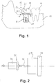
- a positive connection section is provided between the implant 16 and the superstructure 18 , in particular to prevent angular deviations in the longitudinal and circumferential directions with respect to the fastening screw axis.
- This connecting portion is made of a suitably shaped projection 24, which is integrally formed at the free end of the implant sixteenth
- the superstructure 18 has a complementary fitting section 26 , so that the superstructure 18 can be fitted onto the implant 16 with a precise fit and then screwed tight.
- the implant 16 is inserted into the jaw 10 by the dentist after removal of the tooth to be replaced and surgical exposure of the jaw bone. Immediately after insertion or after healing and, if necessary, surgical exposure of the attachment 24 of the implant the jaw situation is mapped conventionally.
- a pin insert is preferably previously inserted into the threaded bore 20 of the implant 16 , which protrudes a good way over the implant.
- the pin insert is penetrated by a sleeve with an inner fitting surface which can be adjusted exactly in shape engagement with the neck 24 of the implant 16 .
- a workpiece 28 of a suitable size preferably an unprocessed ceramic block, is sonoerosively processed by means of a pin sonotrode 30 to form the through bore 22 (FIG. 1) for the connecting screw engaging in the threaded bore 20 of the implant 16 .
- the pin sonotrode 30 comprises a sonotrode shaft 34 connected to the ultrasound generator and a processing cylinder 36 which has approximately the same diameter as the screw which can be anchored in the threaded bore 20 .
- the pin sonotrode 30 is then moved against the workpiece 28 until the hole thus formed has a sufficient depth to form the through hole 22 in the finished dental prosthetic item 12 .
- the pin sonotrode 30 is replaced by a fitting sonotrode 38 , which is shown in FIG. 3.
- This fit sonotrode 38 was not manufactured individually, but a series component.
- a sonotrode shaft 34 it includes a machining section 40 which has the same contour as the fitting shoulder 24 of the implant 16 .
- a spigot 42 is formed which fits in the incorporated in the workpiece 28 through bore 22 and allows a centered shunting of the complementary to the implant shoulder 24 fitting portion 26 in the workpiece 28th The centering approach has proven itself from practical use, but is not absolutely necessary.
- the fit sonotrode 38 and in particular the machining section 40 are subject to a certain amount of wear, which, if the machining section is dimensioned correctly, is compensated for by the working gap caused by the abrasive, so that the fitting section 26 , and thus the counterpart to the implant attachment 24 , is formed precisely and precisely , can be carried out.
- a fitting adapter 52 is preferably used for carrying out the adjustment process, in particular with regard to the angular position between the workpiece 28 and the shaped sonotrode 44 .
- the fitting adapter 52 has on its opposite end faces the positive form 56 and the negative form 54 of the fitting section 26 , both of which are aligned with one another in the circumferential direction with respect to the longitudinal machining axis A, so that the shoulder 41 of the shaped sonotrode 44 is aligned with the pre-machined fitting section 26 of the workpiece 28 is.
- Finishing of the workpiece 28 is then carried out from the occlusal side by means of conventional machining steps using a second shaped sonotrode.
- the unit formed from the workpiece 28 and the shaped sonotrode 44 in engagement is separated from the ultrasonic generator and connected to the stop 32 , while the counter sonotrode is connected to the ultrasonic generator and aligned with the first shaped sonotrode 44 .
- the workpiece 28 is then finished from the occlusal side.
- the first, rough machining of the fitting section 26 on the workpiece side can also take place by means of the individually manufactured shaped sonotrode 44 , which is followed by sonoerosion as a second machining step by means of the non-individually manufactured fitting sonotrode 38 .
- the processing step according to FIG. 4 would take place before that according to FIG. 3.
- the edge lengths of the polygon 56 on the fitting adapter 52 are to be undersized in terms of their length, so that the fitting adapter 52 can be adjusted in the preform of the later fitting section 26 produced by sinking the shoulder 41 of the shaped sonotrode 44 .
- the implants 26 are made up to suit different jaw sizes in the trade in different sizes. Accordingly, the dimensions of the implant attachments 24 are also different. According to the invention, a range of fitting sonotrodes 38 is therefore provided which is adapted to the implant dimensions available and which can be used for the more precise and faster production of generic tooth replacement parts.
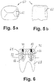
- FIG. 5 (a) and 5 (b) show a top view and side view of a tooth 60 with a mating surface 62 which can also be produced by means of the invention.
- the fitting surface 62 has an approximately dovetail-like shape and serves to insert an attachment part (not shown) from above. It is also important that the fitting surfaces 62 are worked as precisely as possible.
- FIG. 6 shows, in a schematic partially sectional side view of a crown 64 is shown, which is secured to a tooth stub 68, inter alia by means of fastening pins 66, the fixing pins 66 by means of solder glass 70, etc. are soldered to the crown 64 .
- the through bores 72 for the fastening pins 66 are produced in a sonoerosive manner, the fitting sonotrodes according to the invention being used to ensure a highly precise alignment of the bores 72 .
Abstract
Description
Die vorliegende Erfindung betrifft ein Verfahren und eine Vorrichtung zur sonoerosiven Herstellung eines individuellen Formteils mit mindestens einem Passungsabschnitt in der Oberfläche zum formschlüssigen Passungseingriff mit einem konfektionierten Bauteil.The present invention relates to a method and an apparatus for the sonoerosive production of an individual molded part with at least one fitting section in the surface for a form-fitting fitting engagement with a prefabricated component.
Spezieller bezieht sich die Erfindung vornehmlich, aber nicht ausschließlich, auf die Herstellung von keramischen Zahnersatzteilen wie ein- oder mehrteilige Implantat-Suprakonstruktionen oder ähnliche Aufbauten, bei denen üblicherweise ein individuell gefertigtes Zahnersatzteil mit konfektionierten Verankerungselementen für die Befestigung im Kiefer bzw. an angrenzenden Zähnen verbunden werden soll. Unter dem Begriff "konfektioniertes" Bauteil wird im folgenden ein serienmäßig in verschiedenen Ausführungen bzw. Größen verfügbares Bauteil verstanden, wie dies beispielsweise in der Zahnmedizin im Kiefer einsetzbare Implantate sind.More specifically, the invention relates primarily, but not exclusively, to the manufacture of ceramic dental prosthetic items such as single or multi-part implant superstructures or similar structures, in which an individually manufactured dental prosthetic item is usually connected to assembled anchoring elements for attachment in the jaw or adjacent teeth shall be. The term “assembled” component is understood below to mean a component that is available as standard in various designs or sizes, such as implants that can be used in dentistry in the jaw.
Bei herkömmlichen Implantat-Superkonstruktionen wird häufig ein mit einer Bohrung und einem an dem im verankerten Zustand freiliegenden Ende angeformten Passungsabschnitt versehenes Implantat im Kiefer verankert. Der Passungsabschnitt ist im Querschnitt häufig ähnlich einer Sechskantmutter ausgebildet und dient dazu, die Suprakonstruktion lagegenau bezüglich der Längs- und Umfangsrichtung zur Bohrungsachse mit dem Implantat auszurichten. Hierzu ist es erforderlich, daß die kieferseitige Oberfläche der Suprakonstruktion eine zum Passungsabschnitt des Implantats korrespondierende Passungsfläche aufweist. Ferner ist die Suprakonstruktion oft mit einer Durchgangsbohrung versehen, durch die hindurch eine Befestigungsschraube zur Befestigung der Suprakonstruktion in die Implantat-Bohrung eingeschraubt werden kann.In conventional super implant designs, an implant is often anchored in the jaw with a bore and a fitting section formed on the end exposed in the anchored state. The cross section of the fitting section is often similar to that of a hexagon nut and is used to align the superstructure with the implant with respect to the longitudinal and circumferential directions of the bore axis. For this purpose, it is necessary that the surface of the superstructure on the jaw side has a fitting surface corresponding to the fitting section of the implant. Furthermore, the superstructure is often provided with a through hole through which a fastening screw for fastening the superstructure can be screwed into the implant hole.
Herkömmlicherweise werden Zahn-Suprakonstruktionen aus metallischen Werkstoffen konfektioniert oder gegossen. Wünschenswert wäre es, sie aus harten keramischen Werkstoffen zu bilden. Aus US-A-3 971 133, DE-A-3 928 684 und DE-A-4 342 078 ist es bekannt, keramische Zahnersatzteile mittels sonoerosiver Verfahren herzustellen, wobei es sich jedoch stets um Brücken- oder Kronenkonstruktionen handelt, die auf vorbearbeitete Zahnstümpfe aufgesetzt werden. Bei der Verbindung von Krone und individuell präpariertem Stumpf findet eine Fassung mit einer konfektionierten Fläche nicht statt.Traditionally, tooth superstructures are made up or cast from metallic materials. It would be desirable to make them from hard ceramic materials form. From US-A-3 971 133, DE-A-3 928 684 and DE-A-4 342 078 it is known to manufacture ceramic tooth replacement parts by means of sonoerosive processes, but these are always bridge or crown constructions that are pre-processed Tooth stumps are put on. When connecting the crown and the individually prepared stump, there is no socket with a made-up surface.
Für die Herstellung der eingangs genannten Formteile wie Implantat-Suprakonstruktionen für das paßgenaue Zusammenwirken mit zugeordneten Bauteilen wie Implantaten sind die herkömmlichen sonoerosiven Verfahren nicht geeignet. Denn die Sonotroden unterliegen beim Bearbeitungsvorgang einem merklichen Verschleiß, der die Bearbeitungsgenauigkeit mit zunehmender Eindringtiefe ins Werkstück herabsetzt.The conventional sonoerosive processes are not suitable for the production of the molded parts mentioned at the beginning, such as implant superstructures, for the precise interaction with associated components, such as implants. Because the sonotrodes are subject to noticeable wear during the machining process, which reduces the machining accuracy as the depth of penetration into the workpiece increases.
Daher liegt der Erfindung die Aufgabe zugrunde, ein Verfahren, eine Vorrichtung sowie eine Einrichtung zur sonoerosiven Herstellung eines individuellen Formteils mit mindestens einem Passungsabschnitt in der Oberfläche zum formschlüssigen Passungseingriff mit einem konfektionierten Bauteil anzugeben, wobei die hochgenaue Passung zwischen Formteil und konfektioniertem Bauteil sichergestellt sein soll.The invention is therefore based on the object of specifying a method, a device and a device for the sonoerosive manufacture of an individual molded part with at least one fit section in the surface for positive fit engagement with a prefabricated component, the high-precision fit between the molded part and the prefabricated component being ensured .
Erfindungsgemäß wird diese Aufgabe durch die in den unabhängigen Ansprüchen angegebenen Merkmale gelöst.According to the invention, this object is achieved by the features specified in the independent claims.
Der Grundgedanke der Erfindung besteht darin, daß durch die Verwendung von konfektionierten Passungssonotroden, welche die Passungskontur des zu verbindenden Bauteils, insbesondere des Implantats, aufweisen, eine Bearbeitungssonotrode bereitgestellt wird, mittels der zusätzlich zu der Bearbeitung der restlichen Flächen durch die individuell geformten Formsonotroden die getrennte sonoerosive Bearbeitung des Passungsabschnitts des zu bildenden Formteils erfolgen kann. Diese Bearbeitung der Passungsfläche mittels der konfektionierten Passungssonotrode führt zu einer wesentlich genaueren Formgebung des relevanten Passungsabschnitts als bei Bearbeitung durch die individuell gefertigte Formsonotrode. Denn bei der Herstellung der individuellen Formsonotrode sind eine Reihe von aufeinanderfolgenden Abformvorgängen erforderlich, um aus dem vom Zahnarzt im Patientenmund angefertigten ersten Abdruck die endgültige Formsonotrode zu erhalten, wobei jeder Abformvorgang zwangsläufig mit Abbildungsfehlern verbunden ist. Diese Addition der Abbildungsfehler wirkt sich zwar bei der äußeren Formgebung nicht oder nur sehr gering aus, bei der Passungsfläche hingegen können bereits kleine Ungenauigkeiten große Lageverschiebungen hervorrufen.The basic idea of the invention is that by using assembled fit sonotrodes, which have the fit contour of the component to be connected, in particular the implant, a machining sonotrode is provided, by means of which, in addition to the machining of the remaining surfaces by the individually shaped shaped sonotrodes, the separated one sonoerosive processing of the fit section of the molded part to be formed. This processing of the fit surface by means of the assembled fit sonotrode leads to a much more precise shaping of the relevant fit section than when machining by the individually manufactured shape sonotrode. Because in the production of the individual shaped sonotrode are one A series of successive impressions are required in order to obtain the final shaped sonotrode from the first impression made by the dentist in the patient's mouth, each impression being necessarily associated with imaging errors. This addition of the aberrations does not have any or only a very small effect on the outer shape, but on the fit surface, even small inaccuracies can cause large displacements.
Insgesamt läßt sich eine genauere Formgebung des Bearbeitungsabschnitts bei konfektioniert hergestellten Sonotroden gegenüber durch Abformung gebildeten Sonotroden erzielen, da eine Serienfertigung mit automatisierten Werkzeugmaschinen und Meßeinrichtungen durchgeführt werden kann.Overall, a more precise shaping of the machining section in the case of prefabricated sonotrodes compared to sonotrodes formed by molding can be achieved, since series production can be carried out with automated machine tools and measuring devices.
Schließlich ist es möglich, gezielt bestimmte Übermaße der Passungssonotroden einzustellen, um die Verschleißabweichungen dadurch noch geringer zu halten, so daß das Übermaß etwa dem bei der Bearbeitung auftretenden Verschleiß entspricht. Ebenso können die passungsrelevanten Flächen der Passungssonotrode gezielt untermaßig hergestellt werden, um so den durch die verwendete Schleifmittelsuspension verursachten Arbeitsspalt zu kompensieren.Finally, it is possible to set specific oversizes of the fit sonotrodes in order to keep the wear deviations even smaller, so that the oversize corresponds approximately to the wear that occurs during machining. Likewise, the fit-relevant surfaces of the fit sonotrode can be deliberately undersized in order to compensate for the working gap caused by the abrasive suspension used.
Grundsätzlich kann entweder die individuell hergestellte Formsonotrode oder die konfektionierte Passungssonotrode für den ersten Bearbeitungsschritt herangezogen werden. In der Praxis hat es sich als zweckmäßig erwiesen, zuerst die Formgebung des Passungsabschnitts mittels der Passungssonotrode auszuführen, da der entsprechende Abschnitt der Formsonotrode durch die mehrfache Abformung ein gewisses Untermaß aufweist und daher mit dem bereits geformten Passungsabschnitt normalerweise überhaupt nicht mehr in Eingriff gelangt.Basically, either the individually manufactured shaped sonotrode or the assembled fit sonotrode can be used for the first processing step. In practice, it has proven to be expedient to first carry out the shaping of the fitting section by means of the fitting sonotrode, since the corresponding section of the shaping sonotrode has a certain undersize due to the multiple impressions and therefore normally no longer comes into engagement with the already shaped fitting section.
Es sei betont, daß die Erfindung zur maßgenauen Formgebung einer Vielzahl von Passungsflächen bei Zahnersatzteilen verwendet werden kann. So kommen neben der Anpassung an Implantate die Formung von Passungsflächen für Geschiebeteile oder genaue Durchgangsbohrungen für Befestigungsstifte und - schrauben in Frage.It should be emphasized that the invention can be used for the precise shaping of a large number of mating surfaces in tooth replacement parts. In addition to the adaptation to implants, the shaping of fitting surfaces for attachment parts or precise through holes for fastening pins and screws are also possible.
Die Erfindung wird nachfolgend anhand bevorzugter Ausführungsformen unter Bezugnahme auf die beigefügten Zeichnungen weiter erläutert. Dabei zeigt:
- Figur 1
- einen schematischen Schnitt durch einen Kiefer mit eingesetzter Implantat-Suprakonstruktion,
Figur 2- einen ersten Bearbeitungsschritt bei der Herstellung einer Konstruktion nach Figur 1,
- Figuren 3 und 4
- einen zweiten und einen dritten Bearbeitungsschritt,
- Figuren 5(a) und 5(b)
- eine Draufsicht und eine Seitenansicht einer Geschiebe-Passungsfläche für ein Zahnersatzteil, und
- Figur 6
- eine Schnittansicht einer Zahnkrone mit Befestigungsstiften.
- Figure 1
- 2 shows a schematic section through a jaw with an inserted implant superstructure,
- Figure 2
- a first processing step in the manufacture of a construction according to Figure 1,
- Figures 3 and 4
- a second and a third processing step,
- Figures 5 (a) and 5 (b)
- a plan view and a side view of a attachment fitting surface for a denture part, and
- Figure 6
- a sectional view of a tooth crown with fastening pins.
In der nachfolgenden Beschreibung wird die Erfindung unter Bezugnahme auf den bevorzugten Bereich der Dentalrestaurationen erläutert. Dies ist jedoch nicht als Beschränkung aufzufassen, denn in gleicher oder analoger Weise ist die Erfindung in vielen anderen technischen Bereichen einsetzbar.The invention is explained in the following description with reference to the preferred area of dental restorations. However, this should not be interpreted as a limitation, because the invention can be used in many other technical areas in the same or an analogous manner.
In Figur 1 ist schematisch ein Ausschnitt eines Unterkiefers 10 dargestellt, der eine Implantat-Suprakonstruktion 12 aufweist. Zu Veranschaulichungszwecken ist neben dieser ein natürlicher Zahn 14 dargestellt. Die Implantat-Suprakonstruktion 12 besteht im wesentlichen aus einem Implantat 16 und einer daran befestigten Suprakonstruktion 18 als Nachbildung eines natürlichen Zahnes.FIG. 1 schematically shows a section of a
Das Implantat 16 ist etwa zylindrisch ausgebildet und weist an seiner Zylindermantelfläche eine geeignete Oberflächenstruktur auf, um eine Verankerung im Kiefer 10 zu erleichtern. Die Oberflächenstruktur ist als Außengewinde dargestellt; in gleicher Weise können jedoch auch andere Formen und Strukturen wie Ein- oder Ausbuchtungen vorgesehen werden. Derartige Implantate sind im Stand der Technik bekannt.The
Im Innern des Implantats 16 ist eine zur freien Seite hin offene Axialbohrung 20 mit Innengewinde eingelassen, die zur Aufnahme einer nicht dargestellten Befestigungsschraube dient. Hierzu weist die Suprakonstruktion 18 ebenfalls eine mit der Bohrung 20 axial fluchtende Durchgangsbohrung 22 auf. Durch Anziehen der Befestigungsschraube wird die Suprakonstruktion 18 am Implantat 16 befestigt. Falls gewünscht, kann der Schraubenkopf mittels geeigneter Dentalzemente überdeckt werden.In the interior of the
Bei derartigen Implantat-Suprakonstruktionen 12 ist es wichtig, daß das fertige Zahnersatzteil, also die Suprakonstruktion 18, bezüglich des Implantats 16 genau so ausgerichtet ist, wie vom Zahntechniker bei der Modellierung des Zahnersatzteils vorgesehen.In the case of
Um dies sicherzustellen, ist zwischen Implantat 16 und Suprakonstruktion 18 ein formschlüssiger Verbindungsabschnitt vorgesehen, insbesondere um Winkelabweichungen in Längs- und Umfangsrichtung bezüglich der Befestigungsschraubenachse zu verhindern. Dieser Verbindungsabschnitt besteht aus einem geeignet geformten Ansatz 24, der am freien Ende des Implantats 16 angeformt ist. Die Suprakonstruktion 18 weist einen dazu komplementären Passungsabschnitt 26 auf, so daß die Suprakonstruktion 18 paßgenau auf das Implantat 16 aufgesetzt und anschließend festgeschraubt werden kann.To ensure this, a positive connection section is provided between the
Der Ansatz 24 und der Verbindungsabschnitt 26 können im Querschnitt eckig, z.B. drei- , vier- sechs- oder achteckig sein, wobei die bei Schraubenmuttern übliche Sechseckform bevorzugt ist. Auch andere, von der Kreisform abweichende Gestaltungen sind anwendbar. Falls bewußt ein Drehversatz um die Befestigungslängsachse zugelassen und nur ein Kippversatz vermieden werden soll, kann auch eine kreisrunde Kontur gewählt werden.The
Nachfolgend wird ein Verfahren zur Herstellung einer erfindungsgemäßen Implantat-Suprakonstruktion 12 erläutert.A method for producing an
Zunächst wird vom Zahnarzt nach Entfernen des zu ersetzenden Zahnes und chirurgischer Freilegung des Kieferknochens das Implantat 16 im Kiefer 10 eingesetzt. Unmittelbar nach Eingliederung oder nach erfolgter Einheilung und gegebenenfalls chirurgischer Freilegung des Ansatzes 24 des Implantats wird die Kiefersituation konventionell abgeformt. Um die genaue Lage des Implantats 16 in den Abdruck zu übernehmen, wird vorzugsweise vorher ein Stifteinsatz in die Gewindebohrung 20 des Implantats 16 eingesetzt, der ein gutes Stück über das Implantat herausragt. Der Stifteinsatz ist durchsetzt eine Hülse mit einer inneren Paßfläche, die exakt in Formeingriff mit dem Ansatz 24 des Implantats 16 justiert werden kann.First of all, the
Anschließend wird aus einem Modellmaterial, vorzugsweise Gips, ein Positivmodell der Kiefersituation gebildet, das am Boden der durch die Restauration zu füllenden Zahnlücke eine Abbildung des Implantatansatzes 24 mit der durch die Hülse des Stifteinsatzes erzeugte Paßkontur aufweist. Ferner umfaßt das Positivmodell ein etwa hülsenförmiges Modellimplantat, das durch seine Justierung an der im Abdruck fixierten Hülse vor der Herstellung des Positivmodells vorzugsweise durch Ausgießen des Abdrucks etwa mit Gipsmasse in der gleichen Lage, Längs- sowie Umfangsorientierung im Positivmodell angeordnet ist wie das Implantat 16 im Kieferknochen 10.A positive model of the jaw situation is then formed from a model material, preferably plaster, which has an image of the
Um die freiliegende Fläche des Modellimplantats, insbesondere um dessen Ansatz, herum formt der Zahntechniker aus einem plastischen und erhärtenden Werkstoff anschließend ein Modell der Suprakonstruktion, also des zu formenden Zahnersatzteils, oder eines Teil davon.The dental technician then forms a model of the superstructure, that is, the part of the denture to be molded, from a plastic and hardening material around the exposed surface of the model implant, in particular around its base.
Nach dem Abnehmen und Aushärten des Zahnersatzmodells werden die beiden Formsonotroden für die beidseitige sonoerosive Herausarbeitung der Suprakonstruktion geformt. Dazu wird zunächst die spätere Bearbeitungslängsachse definiert, die fluchtend mit der Achse des Stifteinsatzes festgelegt wird. Anschließend wird das Zahnersatzmodell auf ein Ausrichtteil aufgesteckt, das die Form des Implantatansatzes 24 und des in die Gewindebohrung 20 eingesteckten Stifteinsatzes aufweist. Besondere Sorgfalt gilt der parallelen Ausrichtung des Stifteinsatzes zur Bearbeitungslängsachse. Danach wird der Äquatorialverlauf des Zahnersatzmodells bezogen auf die Bearbeitungslängsachse bestimmt und mittels herkömmlicher Techniken, wie sie beispielsweise in den oben erwähnten Druckschriften beschrieben sind, die okklusale Formsonotrode gebildet. Ebenfalls auf bekannte Weise wird anschließend die das Werkstück von der Kieferseite bearbeitende Gegensonotrode hergestellt.After the denture model has been removed and hardened, the two shaped sonotrodes are shaped for the double-sided sonoerosive processing of the superstructure. For this purpose, the later machining longitudinal axis is first defined, which is aligned with the axis of the pin insert. The dental prosthesis model is then placed on an alignment part, which has the shape of the
Nun beginnt der eigentliche Herstellungsvorgang für die Suprakonstruktion 18, der in den Figuren 2 bis 4 näher dargestellt ist.Now the actual manufacturing process for the
Wie in Figur 2 dargestellt, wird ein Werkstück 28 geeigneter Größe, vorzugsweise ein unbearbeiteter Keramikblock, mittels einer Stiftsonotrode 30 zur Ausbildung der Durchgangsbohrung 22 (Figur 1) für die in das Gewindebohrung 20 des Implantats 16 eingreifende Verbindungsschraube sonoerosiv bearbeitet.As shown in FIG. 2, a
Zur Vereinfachung der zeichnerischen Darstellung sind in den Figuren 2 bis 4 der mit der jeweiligen Sonotrode gekoppelte Ultraschallgenerator sowie die zugeordneten Führungen und Halterungen außer dem Anschlag 32 nicht dargestellt.To simplify the drawing, FIGS. 2 to 4 do not show the ultrasound generator coupled to the respective sonotrode and the associated guides and holders apart from the
Die Stiftsonotrode 30 umfaßt einen mit dem Ultraschallgenerator verbundenen Sonotrodenschaft 34 und einen Bearbeitungszylinder 36, der etwa den gleichen Durchmesser aufweist wie die in der Gewindebohrung 20 verankerbare Schraube. Die Stiftsonotrode 30 wird dann gegen das Werkstück 28 verfahren, bis das so gebildete Loch eine ausreichende Tiefe zur Bildung der Durchgangsbohrung 22 im fertigen Zahnersatzteil 12 aufweist.The
Nach Fertigstellung der Durchgangsbohrung 22 wird die Stiftsonotrode 30 durch eine Passungssonotrode 38 ersetzt, was in Figur 3 dargestellt ist. Diese Passungssonotrode 38 ist nicht individuell angefertigt worden, sondern ein Serienbauteil. Es umfaßt neben einem Sonotrodenschaft 34 einen Bearbeitungsabschnitt 40, der die gleiche Kontur wie der Paßansatz 24 des Implantats 16 aufweist. Ferner ist vor dem Bearbeitungsabschnitt 40 ein Zentrieransatz 42 angeformt, der in die im Werkstück 28 eingearbeitete Durchgangsbohrung 22 paßt und einen zentrierten Verschub des zu dem Implantatansatz 24 komplementären Passungsabschnitts 26 in das Werkstück 28 ermöglicht. Der Zentrieransatz hat sich aus der praktischen Anwendung bewährt, ist jedoch nicht unbedingt erforderlich. Während dieses Bearbeitungsvorgangs unterliegt die Passungssonotrode 38 und insbesondere der Bearbeitungsabschnitt 40 einem gewissen Verschleiß, der bei richtiger Bemaßung des Bearbeitungsabschnitts etwa durch den durch das Schleifmittel verursachten Arbeitsspalt kompensiert wird, so daß eine exakte und paßgenaue Ausbildung des Passungsabschnitts 26, mithin des Gegenstücks zum Implantatansatz 24, durchgeführt werden kann.After completion of the through
Anschließend wird die Passungssonotrode 38 durch die in Figur 4 gezeigte kieferseitige Formsonotrode 44 ersetzt. Diese Formsonotrode 44 weist ein Abbild 41 des Implantatansatzes 24 sowie einen davor geformten Zentriervorsprung 46 auf, der im wesentlichen die gleiche Aufgabe hat wie der Zentrieransatz 42 der Passungssonotrode 38. Ferner hat die Formsonotrode einen glockenartigen Mantelabschnitt 48, dessen Innenfläche 50 eine Negativform eines Teils des vom Zahntechniker gebildeten Zahnersatzmodells darstellt.The
Um eine positionsgenaue Ausrichtung der Formsonotrode 44 zu ermöglichen, wird vorzugsweise ein Paßadapter 52 für die Durchführung des Justiervorgangs, insbesondere bezüglich der Winkelposition zwischen Werkstück 28 und Formsonotrode 44 eingesetzt. Der Paßadapter 52 weist an seinen gegenüberliegenden Stirnseiten die Positivform 56 und die Negativform 54 des Passungsabschnitts 26 auf, die beide zueinander in Umfangsrichtung bezüglich der Bearbeitungslängsachse A gleich ausgerichtet sind, so daß der Ansatz 41 der Formsonotrode 44 zu dem vorgearbeiteten Passungsabschnitt 26 des Werkstücks 28 ausgerichtet ist.In order to enable a precise alignment of the shaped
Nach Beendigung der Einjustierung der Formsonotrode 44 wird der Paßadapter 52 entfernt und die Formsonotrode unter Einleitung von Ultraschall in den Sonotrodenschaft 34 soweit in das Werkstück verfahren, bis alle mit dem Werkzeug zu fertigenden Flächen des Werkstücks 28 herausgearbeitet sind.After the adjustment of the
Eine Bearbeitung des Passungsabschnitts 26 durch den Ansatz 41 der Formsonotrode 44 erfolgt vorzugsweise nicht. Bei der Bearbeitung des Werkstücks 28 durch die Innenfläche 50 der Formsonotrode 44 greift der Ansatz 41 formgerecht in die durch den Bearbeitungsabschnitt 40 der Passungssonotrode herausgearbeitete Form. Das Ende dieses Bearbeitungsschrittes ist dann erreicht, wenn der Ansatz 41 der Formsonotrode 44 vollständig in den Passungsabschnitt 26 des Werkstücks 28 eintaucht.The
Der Ansatz 41 der Formsonotrode 44 ist bei deren Herstellung über mehrere Abformschritte in seiner Genauigkeit limitiert und insbesondere an den Kanten des Vielecks zu klein ausgebildet oder verrundet. Je nach dieser Genauigkeit wird der Passungsabschnitt 26 beim Einsenken der Formsonotrode 44 durch den Ansatz 41 mehr oder weniger bearbeitet.The
Aufgrund der zusätzlich notwendigen Berücksichtigung des Arbeitsspaltes bei der sonoerosiven Bearbeitung hat es sich ferner bewährt, für die Bearbeitung des Werkstücks 28 mit der Passungssonotrode 38 und der Formsonotrode 44 dieselbe Schleifmittelaufschlämmung zu verwenden.Due to the additional necessary consideration of the working gap in the sonoserosive machining, it has also proven to be useful to use the same abrasive slurry for machining the
Es ist dabei möglich, die Bearbeitung durch die Formsonotrode in mehrere Teilschritte aufzuteilen. Insbesondere können auch zwei identische Formsonotroden verwendet werden, die die gewünschte Form durch aufeinanderfolgendes Einsenken beider Sonotroden im Sinne einer Schrupp- und Schlichtbearbeitung erzeugen. Bei der Schlichtbearbeitung wird dabei eine neue Formsonotrode 44 verwendet, welche bis zur vollständigen Bearbeitung der kieferseitigen Form der Implantat-Suprakonstruktion 12 nur wenig Volumen des Werkstücks 28 zerspant. Ferner können sich der oben beschriebenen Bearbeitung im Stand der Technik bekannte Verfahrensschritte zur Fertigbearbeitung des Werkstücks 28 von der bearbeiteten Seite anschließen.It is possible to divide the processing by the shaped sonotrode into several sub-steps. In particular, two identical shaped sonotrodes can also be used, which produce the desired shape by successively sinking both sonotrodes in the sense of roughing and finishing. During the finishing process, a new shaped
Anschließend wird mittels herkömmlicher Bearbeitungsschritte eine Fertigbearbeitung des Werkstücks 28 von der okklusalen Seite mittels einer zweiten Formsonotrode durchgeführt. Kurz gesagt wird hierzu die aus Werkstück 28 und im Eingriff befindlicher Formsonotrode 44 gebildete Einheit vom Ultraschallgenerator getrennt und mit dem Anschlag 32 verbunden, während die Gegensonotrode mit dem Ultraschallgenerator verbunden und zu der ersten Formsonotrode 44 ausgerichtet wird. Danach erfolgt die Fertigbearbeitung des Werkstücks 28 von der Okklusalseite her.Finishing of the
Gemäß einer zweiten Ausführungsform des erfindungsgemäßen Bearbeitungsverfahrens kann die erste, grobe Bearbeitung des werkstückseitigen Passungsabschnitts 26 auch mittels der individuell gefertigten Formsonotrode 44 erfolgen, dem sich als zweiter Bearbeitungsschritt die Sonoerosion mittels der nicht individuell gefertigten Passungssonotrode 38 anschließt. Bei dieser Ausführungsform der Erfindung würde also der Bearbeitungsschritt nach Figur 4 vor dem nach Figur 3 erfolgen. In diesem Fall sind die Kantenlängen des Vielecks 56 am Paßadapter 52 bezüglich ihrer Länge unterzudimensionieren, damit der Paßadapter 52 in der durch Einsenken des Ansatzes 41 der Formsonotrode 44 erzeugten Vorform des späteren Passungsabschnitts 26 einjustiert werden kann.According to a second embodiment of the machining method according to the invention, the first, rough machining of the
Die Implantate 26 sind zur Anpassung an unterschiedliche Kiefergrößen im Handel in verschiedenen Größen konfektioniert. Dementsprechend sind die Maße der Implantatansätze 24 auch unterschiedlich. Erfindungsgemäß wird daher ein an die erhältlichen Implantatmaße angepaßtes Sortiment an Passungssonotroden 38 bereitgestellt, die zur genaueren und schnelleren Fertigung von gattungsgemäßen Zahnersatzteilen verwendet werden können.The
In den Figuren 5(a) und 5(b) sind in Draufsicht und Seitenansicht ein Zahn 60 mit einer ebenfalls mittels der Erfindung herstellbaren Passungsfläche 62 dargestellt. Die Passungsfläche 62 hat eine etwa schwalbenschwanzartige Form und dient dazu, ein nicht dargestelltes Geschiebeteil von oben einzuschieben. Dabei kommt es ebenfalls darauf an, daß die Passungsflächen 62 möglichst genau gearbeitet sind.5 (a) and 5 (b) show a top view and side view of a
In Figur 6 ist in einer schematischen teilgeschnittenen Seitenansicht eine Krone 64 dargestellt, die unter anderem mittels Befestigungsstiften 66 an einem Zahnstumpf 68 befestigt ist, wobei die Befestigungsstiften 66 mittels Glaslot 70 o.ä. an der Krone 64 angelötet sind. Auf sonoerosivem Wege werden dabei die Durchgangsbohrungen 72 für die Befestigungsstifte 66 gefertigt, wobei die erfindungsgemäßen Passungssonotroden verwendet werden, um eine hochgenaue Ausrichtung der Bohrungen 72 sicherzustellen.6 shows, in a schematic partially sectional side view of a
Claims (11)
Applications Claiming Priority (2)
| Application Number | Priority Date | Filing Date | Title |
|---|---|---|---|
| DE19501699 | 1995-01-20 | ||
| DE19501699A DE19501699A1 (en) | 1995-01-20 | 1995-01-20 | Sonoerosive superstructure |
Publications (2)
| Publication Number | Publication Date |
|---|---|
| EP0722698A2 true EP0722698A2 (en) | 1996-07-24 |
| EP0722698A3 EP0722698A3 (en) | 1996-12-27 |
Family
ID=7751956
Family Applications (1)
| Application Number | Title | Priority Date | Filing Date |
|---|---|---|---|
| EP96100787A Withdrawn EP0722698A3 (en) | 1995-01-20 | 1996-01-19 | Method and device for the sono-erosive manufacturing of an individual preform |
Country Status (3)
| Country | Link |
|---|---|
| US (1) | US5775911A (en) |
| EP (1) | EP0722698A3 (en) |
| DE (1) | DE19501699A1 (en) |
Families Citing this family (9)
| Publication number | Priority date | Publication date | Assignee | Title |
|---|---|---|---|---|
| DE19753577A1 (en) * | 1997-12-03 | 1999-06-17 | Ralf Dr Schroeder | Atraumatic closed artificial tooth implant |
| BR9805906A (en) * | 1998-12-29 | 2000-09-05 | Silvio De Luca | Support device for making dental prosthetic components |
| EP1143915B1 (en) * | 1999-01-08 | 2004-12-01 | 3M Innovative Properties Company | Dental mill blanks |
| US6991853B2 (en) * | 2003-05-29 | 2006-01-31 | Biogénie Projetos Ltda. | Blank from which a customized prosthetic part can be machined |
| US8403667B2 (en) * | 2006-11-22 | 2013-03-26 | Ch Scientific, Llc | Dental implant |
| US8016644B2 (en) * | 2007-07-13 | 2011-09-13 | UNIVERSITé LAVAL | Method and apparatus for micro-machining a surface |
| EP2862538B1 (en) * | 2012-07-19 | 2018-05-30 | GC Corporation | Dental block |
| DE102015212606B3 (en) * | 2015-07-06 | 2016-10-13 | Sirona Dental Systems Gmbh | Manufacturing process for dental prosthesis and veneer structure |
| JP6876297B2 (en) * | 2017-05-16 | 2021-05-26 | 株式会社不二製作所 | How to polish artificial teeth |
Citations (3)
| Publication number | Priority date | Publication date | Assignee | Title |
|---|---|---|---|---|
| EP0225513A2 (en) * | 1985-12-13 | 1987-06-16 | Herbert Walter | Method and device for making dental prostheses |
| DE3928684A1 (en) * | 1989-08-30 | 1991-04-04 | Hahn Rainer | SONOTRODE |
| DE4342078A1 (en) * | 1992-12-12 | 1994-06-16 | Thera Ges Fuer Patente | Ultrasonic machining sonotrode mfg. system for dental prosthesis mfr - uses negative mould of ultrasonic sonotrode crown to mfr. machining sonotrode |
Family Cites Families (9)
| Publication number | Priority date | Publication date | Assignee | Title |
|---|---|---|---|---|
| US2774193A (en) * | 1955-10-10 | 1956-12-18 | Thatcher | Tools for ultrasonic cutting |
| US3971133A (en) * | 1974-10-29 | 1976-07-27 | Mushabac David R | Dental restoration |
| JPS5935743B2 (en) * | 1979-01-24 | 1984-08-30 | 株式会社井上ジャパックス研究所 | Ultrasonic grinding equipment |
| DE3735558A1 (en) * | 1987-10-21 | 1989-05-03 | Heraeus Edelmetalle Gmbh | METHOD FOR PRODUCING DENTAL SPARE PARTS, LIKE CROWN OR BRIDGES, BY MEANS OF SPARK EDM |
| US5224049A (en) * | 1990-04-10 | 1993-06-29 | Mushabac David R | Method, system and mold assembly for use in preparing a dental prosthesis |
| DE4138803A1 (en) * | 1991-11-26 | 1993-05-27 | Krupp Medizintechnik | Dental replacement mfr. e.g. crowns, bridges etc. - using metal coated shaping tool for ultrasonic erosion of ceramic workpiece or shaped electrode for spark erosion of solid graphite workpiece |
| DE4332065C2 (en) * | 1992-09-24 | 1998-07-09 | Thera Ges Fuer Patente | Ultrasonic processing device and method for processing workpieces using the ultrasonic processing device |
| US5302127A (en) * | 1993-06-01 | 1994-04-12 | Crisio Jr Raymond A | Dental implant stress stabilizer |
| DE4402511C1 (en) * | 1994-01-28 | 1995-05-04 | Guenter Ruebeling | Method and device for forming dental prosthetic frames to be fixed on implants |
-
1995
- 1995-01-20 DE DE19501699A patent/DE19501699A1/en not_active Withdrawn
-
1996
- 1996-01-19 EP EP96100787A patent/EP0722698A3/en not_active Withdrawn
- 1996-01-22 US US08/589,126 patent/US5775911A/en not_active Expired - Fee Related
Patent Citations (3)
| Publication number | Priority date | Publication date | Assignee | Title |
|---|---|---|---|---|
| EP0225513A2 (en) * | 1985-12-13 | 1987-06-16 | Herbert Walter | Method and device for making dental prostheses |
| DE3928684A1 (en) * | 1989-08-30 | 1991-04-04 | Hahn Rainer | SONOTRODE |
| DE4342078A1 (en) * | 1992-12-12 | 1994-06-16 | Thera Ges Fuer Patente | Ultrasonic machining sonotrode mfg. system for dental prosthesis mfr - uses negative mould of ultrasonic sonotrode crown to mfr. machining sonotrode |
Also Published As
| Publication number | Publication date |
|---|---|
| DE19501699A1 (en) | 1996-07-25 |
| US5775911A (en) | 1998-07-07 |
| EP0722698A3 (en) | 1996-12-27 |
Similar Documents
| Publication | Publication Date | Title |
|---|---|---|
| EP1653879B1 (en) | Blank and method for producing a dental crown | |
| EP3348227B1 (en) | Method for producing a three-dimensional model of a section of a jaw | |
| DE102016114251A1 (en) | Dental restoration preform and method of making the same | |
| WO2004060197A1 (en) | Method for automatically creating a dental superstructure for joining to an implant | |
| DE112005000864B4 (en) | Method for producing a dental fitting | |
| DE102006050457B4 (en) | Method for producing a head part of a dental implant and manufacturing kit for such a method | |
| EP0722698A2 (en) | Method and device for the sono-erosive manufacturing of an individual preform | |
| EP0444182B1 (en) | Process for producing a tooth crown with the aid of two sonotrodes | |
| DE102014106331A1 (en) | Workpiece carrier | |
| EP0904743A2 (en) | Method for the fabrication of dental prosthesis and implants by means of CAD/CAM-machines using prefabricated elements | |
| EP0796063B1 (en) | Process for the customised manufacture of dental prosthetic articles and dental treatment using same | |
| CH711922A2 (en) | Denture system with a first supply part, in particular a ceramic implant, and a second supply part. | |
| EP0794742B1 (en) | Connecting member between a mandibular implant fixed in the jaw and a dental prosthesis and process for producing the same | |
| EP3666224B1 (en) | Dental prosthesis with connection sleeve and kit | |
| EP1582172A1 (en) | Method for manufacturing a dental crown | |
| EP3930625A1 (en) | Method for producing a moulded body and moulded body | |
| DE102022133401B3 (en) | Method for producing a dental prosthesis, adapter, blank and set of adapter and blank, set of several adapters | |
| DE202017105987U1 (en) | abutment | |
| DE102004034800C5 (en) | Body for dental crown abutment system | |
| DE102017122788B4 (en) | abutment | |
| EP3245976B1 (en) | Method for manufacturing a dental prosthesis | |
| DE19956424B4 (en) | Dental horizontal screw | |
| WO2014170111A1 (en) | Method for producing a precision model of a set of teeth for producing/adapting a dental prosthesis | |
| DE102008022575A1 (en) | Method for producing dental workpieces e.g. abutment of a dental implant by a copy milling unit, comprises determining the dimensions of the workpiece by scanning a model and then transferring to molded blank by a rotary machine tool | |
| DE2115682A1 (en) | An implant that can be inserted into a partially edentulous or edentulous jaw, a cap that can be placed on the implant, a transfer pin that can be inserted into the cap, and a method for producing a working model of a jaw provided with an implant using the cap and the transfer pin |
Legal Events
| Date | Code | Title | Description |
|---|---|---|---|
| PUAI | Public reference made under article 153(3) epc to a published international application that has entered the european phase |
Free format text: ORIGINAL CODE: 0009012 |
|
| AK | Designated contracting states |
Kind code of ref document: A2 Designated state(s): CH DE FR GB IT LI |
|
| PUAL | Search report despatched |
Free format text: ORIGINAL CODE: 0009013 |
|
| AK | Designated contracting states |
Kind code of ref document: A3 Designated state(s): CH DE FR GB IT LI |
|
| 17P | Request for examination filed |
Effective date: 19970625 |
|
| STAA | Information on the status of an ep patent application or granted ep patent |
Free format text: STATUS: THE APPLICATION IS DEEMED TO BE WITHDRAWN |
|
| 18D | Application deemed to be withdrawn |
Effective date: 20000801 |