EP0722548B1 - Poppet valve having external adjustment for a flow restrictor - Google Patents
Poppet valve having external adjustment for a flow restrictor Download PDFInfo
- Publication number
- EP0722548B1 EP0722548B1 EP94930043A EP94930043A EP0722548B1 EP 0722548 B1 EP0722548 B1 EP 0722548B1 EP 94930043 A EP94930043 A EP 94930043A EP 94930043 A EP94930043 A EP 94930043A EP 0722548 B1 EP0722548 B1 EP 0722548B1
- Authority
- EP
- European Patent Office
- Prior art keywords
- valve
- poppet
- throttle ring
- guide
- seat
- Prior art date
- Legal status (The legal status is an assumption and is not a legal conclusion. Google has not performed a legal analysis and makes no representation as to the accuracy of the status listed.)
- Expired - Lifetime
Links
- 238000007789 sealing Methods 0.000 claims abstract description 24
- 239000012530 fluid Substances 0.000 claims description 4
- 230000013011 mating Effects 0.000 claims description 2
- 230000003628 erosive effect Effects 0.000 abstract description 7
- 210000004907 gland Anatomy 0.000 description 8
- 238000012856 packing Methods 0.000 description 5
- 230000008901 benefit Effects 0.000 description 2
- 239000000463 material Substances 0.000 description 2
- 239000004604 Blowing Agent Substances 0.000 description 1
- 238000005266 casting Methods 0.000 description 1
- 238000004140 cleaning Methods 0.000 description 1
- 238000002485 combustion reaction Methods 0.000 description 1
- 230000006835 compression Effects 0.000 description 1
- 238000007906 compression Methods 0.000 description 1
- 230000000694 effects Effects 0.000 description 1
- 230000006872 improvement Effects 0.000 description 1
- 239000002184 metal Substances 0.000 description 1
- 230000004048 modification Effects 0.000 description 1
- 238000012986 modification Methods 0.000 description 1
- 238000010926 purge Methods 0.000 description 1
- 230000008707 rearrangement Effects 0.000 description 1
- XLYOFNOQVPJJNP-UHFFFAOYSA-N water Substances O XLYOFNOQVPJJNP-UHFFFAOYSA-N 0.000 description 1
Images


Classifications
-
- B—PERFORMING OPERATIONS; TRANSPORTING
- B08—CLEANING
- B08B—CLEANING IN GENERAL; PREVENTION OF FOULING IN GENERAL
- B08B9/00—Cleaning hollow articles by methods or apparatus specially adapted thereto
- B08B9/02—Cleaning pipes or tubes or systems of pipes or tubes
- B08B9/027—Cleaning the internal surfaces; Removal of blockages
- B08B9/032—Cleaning the internal surfaces; Removal of blockages by the mechanical action of a moving fluid, e.g. by flushing
- B08B9/0321—Cleaning the internal surfaces; Removal of blockages by the mechanical action of a moving fluid, e.g. by flushing using pressurised, pulsating or purging fluid
-
- F—MECHANICAL ENGINEERING; LIGHTING; HEATING; WEAPONS; BLASTING
- F16—ENGINEERING ELEMENTS AND UNITS; GENERAL MEASURES FOR PRODUCING AND MAINTAINING EFFECTIVE FUNCTIONING OF MACHINES OR INSTALLATIONS; THERMAL INSULATION IN GENERAL
- F16K—VALVES; TAPS; COCKS; ACTUATING-FLOATS; DEVICES FOR VENTING OR AERATING
- F16K1/00—Lift valves or globe valves, i.e. cut-off apparatus with closure members having at least a component of their opening and closing motion perpendicular to the closing faces
- F16K1/32—Details
- F16K1/52—Means for additional adjustment of the rate of flow
- F16K1/526—Means for additional adjustment of the rate of flow for limiting the maximum flow rate, using a second valve
-
- F—MECHANICAL ENGINEERING; LIGHTING; HEATING; WEAPONS; BLASTING
- F28—HEAT EXCHANGE IN GENERAL
- F28G—CLEANING OF INTERNAL OR EXTERNAL SURFACES OF HEAT-EXCHANGE OR HEAT-TRANSFER CONDUITS, e.g. WATER TUBES OR BOILERS
- F28G15/00—Details
-
- B—PERFORMING OPERATIONS; TRANSPORTING
- B08—CLEANING
- B08B—CLEANING IN GENERAL; PREVENTION OF FOULING IN GENERAL
- B08B2230/00—Other cleaning aspects applicable to all B08B range
- B08B2230/01—Cleaning with steam
Definitions
- This invention relates generally to valves and more particularly to poppet valves which have an internal restrictor which is externally adjustable independently of the operation of the poppet to provide variable rates of fluid flow through the valve when the poppet is fully open.
- Sootblowers used a moving jet of air, water, or most often, steam under high pressure from a moving lance to dislodge combustion deposits from the boiler tubes.
- the control valve for the steam supply be able to open and close relatively quickly, yet have a flow adjustment that can be readily made during operation.
- a valve comprising a valve body having walls defining an inlet chamber and an outlet chamber, said body including a transverse wall separating said inlet and outlet chambers, a valve port opening in said transverse wall, a valve seat on said transverse wall extending around said valve port in said inlet chamber, a valve guide secured in said valve body wall and extending therethrough into said outlet chamber in axial alignment with said valve seat and normal to the plane of the valve seat, said valve guide also extending to the exterior of said valve body and defining an axially extending valve guide bore, a valve poppet having a valve head in said inlet chamber sealingly engageable with said valve seat, said valve poppet having a valve stem extending through said valve guide bore and having an end a spaced distance beyond the exterior of said valve body, cap means secured to said valve stem end, spring means extending around the exterior portion of said valve stem and engageable with said cap means to bias said valve poppet to the closed position with said valve head in sealing engagement with said valve seat, said valve guide having screw
- the valve includes a valve body having an inlet chamber, an outlet chamber, and an integral dividing wall therebetween.
- the inlet opening has a connection flange at the bottom while the outlet opening extends from the side so that the fluid passing through the valve must necessarily make a right angle turn.
- the dividing wall is parallel to the bottom and has a valve port opening centrally located with a hardened valve seat insert pressed in on the lower side of the wall surrounding the opening.
- a valve guide Directly above the opening is mounted a valve guide which is threaded into the top wall and extends downwardly concentric with the valve seat and valve port.
- a valve poppet has a head on the lower side of the wall adapted to move upward and seal against the valve seat.
- the valve stem extends upward through the valve guide which is provided with packing at the upper end which can be compressed by a gland bushing threaded into the valve guide.
- the valve stem extends beyond the gland bushing and through a spring retainer which fits into a slot on the valve stem to support one end of a compression spring whose other end abuts the gland bushing to bias the valve poppet towards the closed position with the head in engagement with the valve seat.
- the end of the valve stem receives a cap which has wrenching flats on the sides and is secured to the valve stem by a transverse pin.
- a throttle ring is threaded on the lower end of the valve guide within the outlet chamber and is generally cup shaped with the side walls having internal threads engaging the external threads on the valve guide.
- the throttle ring has a transverse lower wall having a non-circular or square opening in the center through which the valve stem passes.
- the valve stem has a matching square cross section which fits through the square opening in the throttle ring bottom wall so that as the valve stem is rotated, the throttle ring rotates with it and, because of the threaded connection to the valve guide, moves upwardly and downwardly within the outlet chamber.
- the throttle ring has a cylindrical outer surface which has a slightly smaller diameter than that of the valve port opening in the valve body wall.
- valve seat has a flat sealing face and a cylindrical port surface extending upward from the sealing face continuous with the valve port surface formed on the wall of the valve body.
- the valve poppet in turn, has a flat face adjacent its outer periphery, and a U-shaped groove is formed on the head at the inside of the valve face. The inner side of the groove extends upward beyond the plane of the valve face to define a contour portion having a cylindrical portion spaced closely from the cylindrical port surface and a fillet extending from the upper edge of the cylindrical portion inwardly to the valve stem.
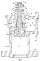
- valve is shown in cross section and will be understood that many features can be varied depending upon the particular application and inlet and outlet connections as well as valve actuation, since these are well known in the art and really form no part of the present invention.
- the valve is shown as having a valve body or housing 10 generally in the form of a one piece casting having an inlet chamber 11 and an outlet chamber 12 separated by a horizontal dividing wall 14.
- This dividing wall has a cylindrical valve port opening 16 centrally located therein with a counterbore 17 at its lower end adapted to receive a valve seat insert 18 preferably formed of a suitable wear resistant material.
- the valve seat insert is pressed in place and provides a flat annular valve seat face 19 on the side exposed in inlet chamber 11.
- the valve seat insert 18 has the same diameter cylindrical bore 20 as that of valve port opening 16 for reasons explained later in greater detail.
- the inlet chamber 11 has an inlet opening 21 together with a connecting flange 22 to make a suitable pipe connection to a source of steam or other blowing agent.
- the outlet chamber 12 has an outlet opening 24 on an extension at its side and this opening is also provided with a flange 25 to make a suitable pipe connection leading to the sootblower or other device supplied by the valve.
- the housing 10 also has a threaded access opening 27 on the side opposite the outlet opening and this opening is normally closed by threaded pipe plug (not shown) .
- the access opening 27 can be used as a connection to a purge system.
- the valve body 10 includes a top wall 29 extending generally parallel to the dividing wall 14 and having an outer surface 30.
- a threaded opening 32 is formed in the top wall 29 to be in concentric alignment with the valve port opening 16 and serves to mount a threaded valve guide 33 screwed into the opening 32 with an outer flange 34 in abutment with the outer surface 30.
- the threaded valve guide 33 has a shank end 36 extending downwardly toward the valve port opening 16 and shank 36 includes a lower counterbore 38 above which is a circular guide portion 39 serving to guide the valve stem as explained in greater detail hereinafter.
- the guide portion 39 is a threaded packing counterbore 41 which receives suitable valve packing 42 at its lower end and a threaded gland bushing 44 at the upper end, it being understood that in normal practice the bushing 44 can be rotated and because of its threaded engagement with the valve guide 33 can serve to compress the packing 42 to prevent leakage along the valve stem.
- the gland bushing 44 also has an internal bore 46 which provides a guide bearing for the valve stem and has a radially extending flange 47 at its upper end which serves not only as a wrenching surface for rotating the gland bushing 44, but also as a spring seat.
- the valve poppet 49 is mounted within the valve body 10 with the head 51 below the valve seat insert 18 and the stem 52 extending upward through the outlet chamber 12.
- the lower portion of the stem directly above head 51 has a portion 54 that is square in cross section (see FIG. 1A) and above that, the remainder of the stem is round or cylindrical at 56 to extend upward through the guide portion 39 of valve guide 33, through the packing 42 and gland bushing 44 to terminate in a tip 59 which includes an annular groove 58 extending around the periphery.
- a valve stem cap 61 is fitted over the tip 59 and held in place by a transverse roll pin 62.
- the cap 61 is preferably provided with wrenching flats on its outer periphery but is prevented from rotating with respect to the tip 59 only by the roll pin 62.
- valve poppet 49 seizes internally so that it will not rotate about the axis of the stem 52, only a limited amount of torque can be applied through the cap 61 before the roll pin 62 is sheared to allow relative rotation between the cap 61 and tip 59. This prevents damage to the internal structure of the valve, such as might occur if rotation of the poppet is tried when the valve is closed, and thereby prevents any internal damage.
- a flat spring retainer 64 which fits in the annular groove 58 and serves to restrain the valve spring 66 which surrounds the valve stem and engages flange 47 on gland bushing 44.
- the spring 66 constantly biases the retainer 64 and hence, the entire valve poppet, upward toward a closed position with the valve head 51 in engagement with the valve seat insert 18.
- the lower end of the valve guide 33 along the shank portion 36 is provided on its external periphery with threads 68 which receive a throttle ring 71 having a threaded sleeve 72 in engagement with the thread 68.
- the throttle ring 71 has a cylindrical outer surface 73 having a diameter slightly smaller than that of the valve port opening 16 and the inlet opening 21 and this surface terminates at its lower end in a bottom wall 74 extending across the lower end of the valve guide 33 and having a central opening 76 formed as a square to matingly receive the square portion 54 of valve stem 52.
- the throttle ring 71 is provided at its lower end with a pair of cap screws 78 threaded into suitable openings in the outer surface 73 on diametrically opposite sides adjacent the bottom wall edge 77 and these cap screws have projecting heads 79 which extend radially outward to define a diameter greater than that of the valve port opening 16. If the throttle ring is moved downward until the edge 77 passes into the valve port opening 16, the screw heads 79 will engage the top of wall 14 to prevent further downward movement of the throttle ring. Thus, it is not possible by inadvertent rotation of the valve stem 52 to have the throttle ring 71 unscrew completely off the valve guide.
- valve When the valve is installed in a sootblower or other device, the valve is opened by an actuator which engages the valve stem cap 61 and moves the valve downward until the valve head 51 is far enough off the valve seat to allow maximum flow through the valve. While the valve is open, the valve stem is rotated by turning the valve stem cap 61 until the throttle ring 71 moves far enough downward to reduce the flow through the outlet opening 24 to the desired rate of flow. Since the restriction required to reduce the flow now takes place between the edge 77 of throttle ring 71 and the upper edge of the valve port opening, any erosion caused by pressure drop occurs at these points and not at the sealing faces 19 on the valve seat and at the valve poppet. Since the wear takes place at non sealing portions of the valve, a certain amount of mechanical erosion or metal removal can occur and if large enough, be compensated for by adjustment of the position of the throttle ring 71 without any loss of sealing when the valve is closed.
- valve head 51 has an end face 81 within the inlet chamber 11, and the end face terminates in a cylindrical periphery 82, which, when the valve is in the closed position, fits within a relief bore 83 formed in the horizontal wall 14 around the valve seat insert 18.
- a short distance above the end face 81 is an annular flat sealing face 84 adapted to make sealing engagement with the valve seat face 19.
- the space between the side 87 and the valve seat bore 20 provides a restriction greater than that between the sealing face 84 and the valve seat face 19 after the valve has opened a very short distance and this restriction continues during the opening movement of the valve as the pressure drop in effect is transferred gradually from the space between edge 88 and valve seat bore 20 to the above mentioned spacing at the throttle ring edge 77 depending upon the position of the throttle ring.
- pressure drop occurring at the sealing faces 84 and 19 is only minimal during the very initial opening and terminal closing of the valve.
Landscapes
- Engineering & Computer Science (AREA)
- General Engineering & Computer Science (AREA)
- Mechanical Engineering (AREA)
- Physics & Mathematics (AREA)
- Fluid Mechanics (AREA)
- Chemical & Material Sciences (AREA)
- Combustion & Propulsion (AREA)
- Lift Valve (AREA)
- Safety Valves (AREA)
Abstract
Description
Claims (7)
- A valve comprising a valve body (10) having walls defining an inlet chamber (11) and an outlet chamber (12), said body including a transverse wall (14) separating said inlet and outlet chambers, a valve port opening (16) in said transverse wall (14), a valve seat (18) on said transverse wall (14) extending around said valve port (16) in said inlet chamber (11), a valve guide (33) secured in said valve body wall and extending therethrough into said outlet chamber (12) in axial alignment with said valve seat (18) and normal to the plane of the valve seat (18), said valve guide (33) also extending to the exterior of said valve body (10) and defining an axially extending valve guide bore (39), a valve poppet (49) having a valve head (51) in said inlet chamber (11) sealingly engageable with said valve seat (18), said valve poppet (49) having a valve stem (52) extending through said valve guide bore (39) and having an end a spaced distance beyond the exterior of said valve body, cap means (61) secured to said valve stem end, spring means (66) extending around the exterior portion of said valve stem (52) and engageable with said cap means (61) to bias said valve poppet (49) to the closed position with said valve head (51) in sealing engagement with said valve seat (18), said valve guide (33) having screw threads on the exterior of the end portion adjacent said valve seat (18), a circular throttle ring (71) threadedly engaged on said valve guide (33) so that relative rotation between said throttle ring (71) and said valve guide (33) moves said throttle ring (71) toward and away from said valve port opening (16), said throttle ring (71) having an end wall extending around said valve stem (52) having a mating noncircular portion (54) adjacent said end wall whereby rotation of said valve poppet (49) moves said throttle ring (71) toward and away from said valve port opening (16), characterised in that said throttle ring (71) has an outer surface (73) with a diameter less than the diameter of said valve port opening (16), and there being at least one removable projection (78,79) on said throttle ring operable to prevent movement of said throttle ring (71) through said valve port opening (16).
- A valve as set forth in Claim 1 wherein said removable projection (78,79) is a cap screw.
- A valve as set forth in Claim 1, including a pair of removable projections (78,79), one each on diametrically opposed portions of said throttle ring outer surface (73).
- A valve as set forth in claim 3 wherein said removable projections (78,79) are cap screws.
- A valve as set forth in any one of the preceding claims wherein said valve has a main restriction to fluid flow downstream of said valve port, said valve poppet (49) defining a valve axis, said valve head (51) having a sealing surface (84) making sealing engagement with said valve seat (18) when said valve is closed, said valve head (51) and valve seat sealing surfaces being flat and in a plane normal to said valve axis, said poppet (49) having a contour surface extending between said sealing surface (84) and said valve stem (52), said contour surface cooperating with said valve port to provide a restriction to fluid flow through said valve when said valve head (51) is moved less than a predetermined distance from side valve seat (18) so that any pressure drop between said inlet (11) and outlet (12) chambers takes place at said restriction between said contour surface and said valve port, said pressure drop taking place between said valve head sealing surface (84) and said valve seat (18) when said valve head (51) is spaced from said valve seat (18) more than said predetermined distance.
- A valve as set forth in Claim 5, wherein said valve port (16) and a portion of said contour surface are cylindrical so that the movement of said valve head (51) past said predetermined distance provides no change in said restriction for a further predetermined distance of movement.
- A valve as set forth in Claim 5 wherein said main restriction is said adjustable throttle ring (71) threaded on said valve guide (33).
Applications Claiming Priority (3)
| Application Number | Priority Date | Filing Date | Title |
|---|---|---|---|
| US134412 | 1987-12-17 | ||
| US08/134,412 US5358212A (en) | 1993-10-08 | 1993-10-08 | Poppet valve having external adjustment for a flow restrictor |
| PCT/US1994/011283 WO1995010722A2 (en) | 1993-10-08 | 1994-10-06 | Poppet valve having external adjustment for a flow restrictor |
Publications (2)
| Publication Number | Publication Date |
|---|---|
| EP0722548A1 EP0722548A1 (en) | 1996-07-24 |
| EP0722548B1 true EP0722548B1 (en) | 1998-03-25 |
Family
ID=22463272
Family Applications (1)
| Application Number | Title | Priority Date | Filing Date |
|---|---|---|---|
| EP94930043A Expired - Lifetime EP0722548B1 (en) | 1993-10-08 | 1994-10-06 | Poppet valve having external adjustment for a flow restrictor |
Country Status (10)
| Country | Link |
|---|---|
| US (1) | US5358212A (en) |
| EP (1) | EP0722548B1 (en) |
| JP (1) | JP2761292B2 (en) |
| KR (1) | KR100194119B1 (en) |
| CN (1) | CN1041958C (en) |
| AU (1) | AU675012B2 (en) |
| CA (1) | CA2172536C (en) |
| DE (1) | DE69409249T2 (en) |
| ES (1) | ES2116620T3 (en) |
| WO (1) | WO1995010722A2 (en) |
Families Citing this family (25)
| Publication number | Priority date | Publication date | Assignee | Title |
|---|---|---|---|---|
| US6164930A (en) * | 1998-06-18 | 2000-12-26 | Flow International Corporation | Apparatus for regulating flow of a pumped substance |
| CN1397719A (en) * | 2001-07-18 | 2003-02-19 | 邓国峰 | Flexible time cross-section controller |
| DE602004012580D1 (en) * | 2004-11-29 | 2008-04-30 | Techspace Aero Sa | Valve with pressure loss fluctuation |
| US7387135B2 (en) * | 2004-12-23 | 2008-06-17 | Mks Instruments, Inc. | Valve assembly having rigid seating surfaces |
| US7311068B2 (en) | 2006-04-17 | 2007-12-25 | Jason Stewart Jackson | Poppet valve and engine using same |
| US7533641B1 (en) | 2006-04-17 | 2009-05-19 | Jason Stewart Jackson | Poppet valve and engine using same |
| KR20080015653A (en) * | 2006-08-16 | 2008-02-20 | 볼보 컨스트럭션 이키프먼트 홀딩 스웨덴 에이비 | Pressure control valve |
| KR100831163B1 (en) * | 2006-11-28 | 2008-05-20 | 한국하니웰 주식회사 | Temperature control valve capable of regulating flow rate delicately |
| DE102007031962A1 (en) * | 2007-07-10 | 2009-01-15 | Krones Ag | metering valve |
| US8205630B2 (en) * | 2008-06-10 | 2012-06-26 | Ausco, Inc. | Low pressure relief valve and method of manufacturing same |
| US8671988B2 (en) * | 2008-09-02 | 2014-03-18 | Emerson Process Management Regulator Technologies, Inc. | Fluid flow control members for use with valves |
| US8146885B2 (en) * | 2008-10-08 | 2012-04-03 | Emerson Process Management Regulator Technologies, Inc. | Field removable bonnet assemblies for use with valves |
| CN102252097A (en) * | 2010-05-19 | 2011-11-23 | 泰科爱尔(北京)科技有限公司 | Gas pressure reducer lift valve |
| CN101825185B (en) * | 2010-06-09 | 2012-07-18 | 卓旦春 | Spool of cut-off valve |
| US9273449B2 (en) * | 2012-10-04 | 2016-03-01 | B/E Aerospace, Inc. | Aircraft galley water distribution manifold |
| JP6316588B2 (en) * | 2013-12-27 | 2018-04-25 | 日本ピストンリング株式会社 | Combining valve and valve seat for internal combustion engine |
| HUE036254T2 (en) * | 2015-03-10 | 2018-06-28 | Pettinaroli Flii Spa | Automatic balancing valve with preset flow rate |
| EP3203346A1 (en) * | 2016-02-02 | 2017-08-09 | Danfoss A/S | Valve, in particular heat exchanger valve |
| CN105864440A (en) * | 2016-05-30 | 2016-08-17 | 合肥通用机械研究院 | Flexible sealing lift valve |
| US11313485B2 (en) * | 2018-01-31 | 2022-04-26 | Zhejiang Sanhua Climate And Appliance Controls Group Co., Ltd | Electric valve and manufacturing method thereof |
| JP6653050B1 (en) | 2018-03-20 | 2020-02-26 | 日鍛バルブ株式会社 | Hollow poppet valve for exhaust |
| JP7190506B2 (en) | 2018-11-12 | 2022-12-15 | 株式会社Nittan | Manufacturing method of engine poppet valve |
| EP3792527A1 (en) * | 2019-09-10 | 2021-03-17 | Alfa Laval Corporate AB | Gasket, fluid flow control valve and method of cleaning such a valve |
| WO2021199190A1 (en) | 2020-03-30 | 2021-10-07 | 日鍛バルブ株式会社 | Method for manufacturing engine poppet valve |
| US20210341140A1 (en) * | 2020-05-01 | 2021-11-04 | International Paper Company | System and methods for controlling operation of a recovery boiler to reduce fouling |
Family Cites Families (9)
| Publication number | Priority date | Publication date | Assignee | Title |
|---|---|---|---|---|
| DE333730C (en) * | 1921-03-18 | Rothe & Siemens Werke Akt Ges | Screw-down valve with screw valve located below the valve seat and coupled to the main valve as a presetting | |
| GB193127A (en) * | 1921-11-15 | 1923-02-15 | James Edward Grainger | Improvements in valves or the like fluid control means |
| US1730322A (en) * | 1927-06-16 | 1929-10-01 | Sullivan Machinery Co | Rock drill |
| US2328010A (en) * | 1940-05-01 | 1943-08-31 | Clayton Manufacturing Co | Check valve |
| US2685294A (en) * | 1949-04-11 | 1954-08-03 | Gold Harold | Wide range flow rate metering valve |
| FR1081174A (en) * | 1953-04-23 | 1954-12-16 | Cie Gen Equip Aeronautique | Sealing device for high pressure fluid |
| US3164364A (en) * | 1962-10-04 | 1965-01-05 | Diamond Power Speciality | Deformable valve head and seat construction |
| US3572631A (en) * | 1969-03-26 | 1971-03-30 | Honeywell Inc | Motorized valve of globe-type |
| US5135198A (en) * | 1991-05-30 | 1992-08-04 | The Babcock & Wilcox Company | Externally adjustable flow restriction control for poppet valves |
-
1993
- 1993-10-08 US US08/134,412 patent/US5358212A/en not_active Expired - Lifetime
-
1994
- 1994-10-06 KR KR1019960701828A patent/KR100194119B1/en not_active IP Right Cessation
- 1994-10-06 CA CA002172536A patent/CA2172536C/en not_active Expired - Fee Related
- 1994-10-06 AU AU79288/94A patent/AU675012B2/en not_active Ceased
- 1994-10-06 CN CN94193699A patent/CN1041958C/en not_active Expired - Fee Related
- 1994-10-06 ES ES94930043T patent/ES2116620T3/en not_active Expired - Lifetime
- 1994-10-06 EP EP94930043A patent/EP0722548B1/en not_active Expired - Lifetime
- 1994-10-06 JP JP6518407A patent/JP2761292B2/en not_active Expired - Lifetime
- 1994-10-06 DE DE69409249T patent/DE69409249T2/en not_active Expired - Fee Related
- 1994-10-06 WO PCT/US1994/011283 patent/WO1995010722A2/en active IP Right Grant
Also Published As
| Publication number | Publication date |
|---|---|
| KR100194119B1 (en) | 1999-06-15 |
| AU675012B2 (en) | 1997-01-16 |
| EP0722548A1 (en) | 1996-07-24 |
| DE69409249D1 (en) | 1998-04-30 |
| AU7928894A (en) | 1995-05-04 |
| CA2172536A1 (en) | 1995-04-20 |
| KR960705165A (en) | 1996-10-09 |
| DE69409249T2 (en) | 1998-07-16 |
| US5358212A (en) | 1994-10-25 |
| JP2761292B2 (en) | 1998-06-04 |
| ES2116620T3 (en) | 1998-07-16 |
| CA2172536C (en) | 1999-04-20 |
| CN1041958C (en) | 1999-02-03 |
| JPH09504077A (en) | 1997-04-22 |
| WO1995010722A2 (en) | 1995-04-20 |
| CN1133084A (en) | 1996-10-09 |
| WO1995010722A3 (en) | 1995-07-13 |
Similar Documents
| Publication | Publication Date | Title |
|---|---|---|
| EP0722548B1 (en) | Poppet valve having external adjustment for a flow restrictor | |
| US2866477A (en) | Combined throttle and stop valve | |
| US4130130A (en) | Valve with variable secondary orifice | |
| US5131425A (en) | Gas pressure regulator with check valve | |
| RU2303186C2 (en) | Valve plug | |
| US4860784A (en) | Non-rising stem valve assembly and method of replacing a permanent seal | |
| US4314582A (en) | Combined pressure-regulator and manual shut-off valve | |
| RU2322628C2 (en) | Control valve | |
| US4211386A (en) | Slow opening cylinder valve | |
| US5546980A (en) | Floating cage cartridge valve and knob | |
| RU2326276C2 (en) | Controlling unit for process control valve, process control valve and methods of valve plug fixing to valve pin | |
| US4041973A (en) | Quick change valve trim assembly | |
| US20050139273A1 (en) | Electromechanically controlled proportional valve | |
| US2001251A (en) | Valve | |
| US5135198A (en) | Externally adjustable flow restriction control for poppet valves | |
| US4763687A (en) | Faucet valve | |
| US5950650A (en) | High pressure regulator | |
| KR200330696Y1 (en) | Structure of controlling exhaustion of safety valve for boiler | |
| EP1178250B1 (en) | Self-closing valve | |
| US4736767A (en) | Fluid flow controller | |
| EP0438285A2 (en) | Valve assembly for high pressure water shut-off gun | |
| US20210062927A1 (en) | Pressure relief valve, service system, and method for servicing pressure relief valve | |
| US5450872A (en) | Constant pressure valve and method | |
| JPS5850150Y2 (en) | Lift valve with diaphragm type actuator | |
| GB2150671A (en) | Control valve |
Legal Events
| Date | Code | Title | Description |
|---|---|---|---|
| PUAI | Public reference made under article 153(3) epc to a published international application that has entered the european phase |
Free format text: ORIGINAL CODE: 0009012 |
|
| 17P | Request for examination filed |
Effective date: 19960503 |
|
| AK | Designated contracting states |
Kind code of ref document: A1 Designated state(s): DE ES FR GB IT |
|
| 17Q | First examination report despatched |
Effective date: 19961112 |
|
| GRAG | Despatch of communication of intention to grant |
Free format text: ORIGINAL CODE: EPIDOS AGRA |
|
| GRAG | Despatch of communication of intention to grant |
Free format text: ORIGINAL CODE: EPIDOS AGRA |
|
| GRAH | Despatch of communication of intention to grant a patent |
Free format text: ORIGINAL CODE: EPIDOS IGRA |
|
| GRAH | Despatch of communication of intention to grant a patent |
Free format text: ORIGINAL CODE: EPIDOS IGRA |
|
| GRAA | (expected) grant |
Free format text: ORIGINAL CODE: 0009210 |
|
| AK | Designated contracting states |
Kind code of ref document: B1 Designated state(s): DE ES FR GB IT |
|
| REF | Corresponds to: |
Ref document number: 69409249 Country of ref document: DE Date of ref document: 19980430 |
|
| ET | Fr: translation filed | ||
| ITF | It: translation for a ep patent filed | ||
| REG | Reference to a national code |
Ref country code: ES Ref legal event code: FG2A Ref document number: 2116620 Country of ref document: ES Kind code of ref document: T3 |
|
| PG25 | Lapsed in a contracting state [announced via postgrant information from national office to epo] |
Ref country code: GB Free format text: LAPSE BECAUSE OF NON-PAYMENT OF DUE FEES Effective date: 19981006 |
|
| PG25 | Lapsed in a contracting state [announced via postgrant information from national office to epo] |
Ref country code: ES Free format text: LAPSE BECAUSE OF NON-PAYMENT OF DUE FEES Effective date: 19981007 |
|
| PLBE | No opposition filed within time limit |
Free format text: ORIGINAL CODE: 0009261 |
|
| STAA | Information on the status of an ep patent application or granted ep patent |
Free format text: STATUS: NO OPPOSITION FILED WITHIN TIME LIMIT |
|
| 26N | No opposition filed | ||
| GBPC | Gb: european patent ceased through non-payment of renewal fee |
Effective date: 19981006 |
|
| PG25 | Lapsed in a contracting state [announced via postgrant information from national office to epo] |
Ref country code: FR Free format text: LAPSE BECAUSE OF NON-PAYMENT OF DUE FEES Effective date: 19990630 |
|
| REG | Reference to a national code |
Ref country code: FR Ref legal event code: ST |
|
| PGFP | Annual fee paid to national office [announced via postgrant information from national office to epo] |
Ref country code: DE Payment date: 19990802 Year of fee payment: 5 |
|
| PG25 | Lapsed in a contracting state [announced via postgrant information from national office to epo] |
Ref country code: DE Free format text: LAPSE BECAUSE OF NON-PAYMENT OF DUE FEES Effective date: 20000801 |
|
| REG | Reference to a national code |
Ref country code: ES Ref legal event code: FD2A Effective date: 19991113 |
|
| PG25 | Lapsed in a contracting state [announced via postgrant information from national office to epo] |
Ref country code: IT Free format text: LAPSE BECAUSE OF NON-PAYMENT OF DUE FEES Effective date: 20051006 |