EP0721745A2 - Clothing for clean rooms - Google Patents
Clothing for clean rooms Download PDFInfo
- Publication number
- EP0721745A2 EP0721745A2 EP95104585A EP95104585A EP0721745A2 EP 0721745 A2 EP0721745 A2 EP 0721745A2 EP 95104585 A EP95104585 A EP 95104585A EP 95104585 A EP95104585 A EP 95104585A EP 0721745 A2 EP0721745 A2 EP 0721745A2
- Authority
- EP
- European Patent Office
- Prior art keywords
- joined
- heat bonding
- unit
- turned down
- portions
- Prior art date
- Legal status (The legal status is an assumption and is not a legal conclusion. Google has not performed a legal analysis and makes no representation as to the accuracy of the status listed.)
- Withdrawn
Links
Images



Classifications
-
- B—PERFORMING OPERATIONS; TRANSPORTING
- B29—WORKING OF PLASTICS; WORKING OF SUBSTANCES IN A PLASTIC STATE IN GENERAL
- B29C—SHAPING OR JOINING OF PLASTICS; SHAPING OF MATERIAL IN A PLASTIC STATE, NOT OTHERWISE PROVIDED FOR; AFTER-TREATMENT OF THE SHAPED PRODUCTS, e.g. REPAIRING
- B29C66/00—General aspects of processes or apparatus for joining preformed parts
- B29C66/01—General aspects dealing with the joint area or with the area to be joined
- B29C66/05—Particular design of joint configurations
- B29C66/10—Particular design of joint configurations particular design of the joint cross-sections
- B29C66/11—Joint cross-sections comprising a single joint-segment, i.e. one of the parts to be joined comprising a single joint-segment in the joint cross-section
- B29C66/114—Single butt joints
- B29C66/1142—Single butt to butt joints
-
- A—HUMAN NECESSITIES
- A41—WEARING APPAREL
- A41D—OUTERWEAR; PROTECTIVE GARMENTS; ACCESSORIES
- A41D13/00—Professional, industrial or sporting protective garments, e.g. surgeons' gowns or garments protecting against blows or punches
- A41D13/02—Overalls, e.g. bodysuits or bib overalls
-
- A—HUMAN NECESSITIES
- A41—WEARING APPAREL
- A41D—OUTERWEAR; PROTECTIVE GARMENTS; ACCESSORIES
- A41D27/00—Details of garments or of their making
- A41D27/24—Hems; Seams
- A41D27/245—Hems; Seams made by welding or gluing
-
- B—PERFORMING OPERATIONS; TRANSPORTING
- B29—WORKING OF PLASTICS; WORKING OF SUBSTANCES IN A PLASTIC STATE IN GENERAL
- B29C—SHAPING OR JOINING OF PLASTICS; SHAPING OF MATERIAL IN A PLASTIC STATE, NOT OTHERWISE PROVIDED FOR; AFTER-TREATMENT OF THE SHAPED PRODUCTS, e.g. REPAIRING
- B29C65/00—Joining or sealing of preformed parts, e.g. welding of plastics materials; Apparatus therefor
- B29C65/02—Joining or sealing of preformed parts, e.g. welding of plastics materials; Apparatus therefor by heating, with or without pressure
- B29C65/08—Joining or sealing of preformed parts, e.g. welding of plastics materials; Apparatus therefor by heating, with or without pressure using ultrasonic vibrations
-
- B—PERFORMING OPERATIONS; TRANSPORTING
- B29—WORKING OF PLASTICS; WORKING OF SUBSTANCES IN A PLASTIC STATE IN GENERAL
- B29C—SHAPING OR JOINING OF PLASTICS; SHAPING OF MATERIAL IN A PLASTIC STATE, NOT OTHERWISE PROVIDED FOR; AFTER-TREATMENT OF THE SHAPED PRODUCTS, e.g. REPAIRING
- B29C65/00—Joining or sealing of preformed parts, e.g. welding of plastics materials; Apparatus therefor
- B29C65/02—Joining or sealing of preformed parts, e.g. welding of plastics materials; Apparatus therefor by heating, with or without pressure
- B29C65/08—Joining or sealing of preformed parts, e.g. welding of plastics materials; Apparatus therefor by heating, with or without pressure using ultrasonic vibrations
- B29C65/083—Joining or sealing of preformed parts, e.g. welding of plastics materials; Apparatus therefor by heating, with or without pressure using ultrasonic vibrations using a rotary sonotrode or a rotary anvil
- B29C65/086—Joining or sealing of preformed parts, e.g. welding of plastics materials; Apparatus therefor by heating, with or without pressure using ultrasonic vibrations using a rotary sonotrode or a rotary anvil using a rotary anvil
-
- B—PERFORMING OPERATIONS; TRANSPORTING
- B29—WORKING OF PLASTICS; WORKING OF SUBSTANCES IN A PLASTIC STATE IN GENERAL
- B29C—SHAPING OR JOINING OF PLASTICS; SHAPING OF MATERIAL IN A PLASTIC STATE, NOT OTHERWISE PROVIDED FOR; AFTER-TREATMENT OF THE SHAPED PRODUCTS, e.g. REPAIRING
- B29C65/00—Joining or sealing of preformed parts, e.g. welding of plastics materials; Apparatus therefor
- B29C65/48—Joining or sealing of preformed parts, e.g. welding of plastics materials; Apparatus therefor using adhesives, i.e. using supplementary joining material; solvent bonding
- B29C65/50—Joining or sealing of preformed parts, e.g. welding of plastics materials; Apparatus therefor using adhesives, i.e. using supplementary joining material; solvent bonding using adhesive tape, e.g. thermoplastic tape; using threads or the like
- B29C65/5042—Joining or sealing of preformed parts, e.g. welding of plastics materials; Apparatus therefor using adhesives, i.e. using supplementary joining material; solvent bonding using adhesive tape, e.g. thermoplastic tape; using threads or the like covering both elements to be joined
-
- B—PERFORMING OPERATIONS; TRANSPORTING
- B29—WORKING OF PLASTICS; WORKING OF SUBSTANCES IN A PLASTIC STATE IN GENERAL
- B29C—SHAPING OR JOINING OF PLASTICS; SHAPING OF MATERIAL IN A PLASTIC STATE, NOT OTHERWISE PROVIDED FOR; AFTER-TREATMENT OF THE SHAPED PRODUCTS, e.g. REPAIRING
- B29C66/00—General aspects of processes or apparatus for joining preformed parts
- B29C66/01—General aspects dealing with the joint area or with the area to be joined
- B29C66/03—After-treatments in the joint area
- B29C66/032—Mechanical after-treatments
- B29C66/0324—Reforming or reshaping the joint, e.g. folding over
- B29C66/03241—Flattening
- B29C66/03242—Flattening of sheets being positioned in abutment, e.g. after folding open of an overlap joint
-
- B—PERFORMING OPERATIONS; TRANSPORTING
- B29—WORKING OF PLASTICS; WORKING OF SUBSTANCES IN A PLASTIC STATE IN GENERAL
- B29C—SHAPING OR JOINING OF PLASTICS; SHAPING OF MATERIAL IN A PLASTIC STATE, NOT OTHERWISE PROVIDED FOR; AFTER-TREATMENT OF THE SHAPED PRODUCTS, e.g. REPAIRING
- B29C66/00—General aspects of processes or apparatus for joining preformed parts
- B29C66/01—General aspects dealing with the joint area or with the area to be joined
- B29C66/03—After-treatments in the joint area
- B29C66/038—Covering the joint by a coating material
- B29C66/0384—Covering the joint by a coating material the coating material being in tape, strip or band form
-
- B—PERFORMING OPERATIONS; TRANSPORTING
- B29—WORKING OF PLASTICS; WORKING OF SUBSTANCES IN A PLASTIC STATE IN GENERAL
- B29C—SHAPING OR JOINING OF PLASTICS; SHAPING OF MATERIAL IN A PLASTIC STATE, NOT OTHERWISE PROVIDED FOR; AFTER-TREATMENT OF THE SHAPED PRODUCTS, e.g. REPAIRING
- B29C66/00—General aspects of processes or apparatus for joining preformed parts
- B29C66/01—General aspects dealing with the joint area or with the area to be joined
- B29C66/05—Particular design of joint configurations
- B29C66/10—Particular design of joint configurations particular design of the joint cross-sections
- B29C66/11—Joint cross-sections comprising a single joint-segment, i.e. one of the parts to be joined comprising a single joint-segment in the joint cross-section
- B29C66/112—Single lapped joints
- B29C66/1122—Single lap to lap joints, i.e. overlap joints
-
- B—PERFORMING OPERATIONS; TRANSPORTING
- B29—WORKING OF PLASTICS; WORKING OF SUBSTANCES IN A PLASTIC STATE IN GENERAL
- B29C—SHAPING OR JOINING OF PLASTICS; SHAPING OF MATERIAL IN A PLASTIC STATE, NOT OTHERWISE PROVIDED FOR; AFTER-TREATMENT OF THE SHAPED PRODUCTS, e.g. REPAIRING
- B29C66/00—General aspects of processes or apparatus for joining preformed parts
- B29C66/01—General aspects dealing with the joint area or with the area to be joined
- B29C66/05—Particular design of joint configurations
- B29C66/10—Particular design of joint configurations particular design of the joint cross-sections
- B29C66/13—Single flanged joints; Fin-type joints; Single hem joints; Edge joints; Interpenetrating fingered joints; Other specific particular designs of joint cross-sections not provided for in groups B29C66/11 - B29C66/12
- B29C66/133—Fin-type joints, the parts to be joined being flexible
-
- B—PERFORMING OPERATIONS; TRANSPORTING
- B29—WORKING OF PLASTICS; WORKING OF SUBSTANCES IN A PLASTIC STATE IN GENERAL
- B29C—SHAPING OR JOINING OF PLASTICS; SHAPING OF MATERIAL IN A PLASTIC STATE, NOT OTHERWISE PROVIDED FOR; AFTER-TREATMENT OF THE SHAPED PRODUCTS, e.g. REPAIRING
- B29C66/00—General aspects of processes or apparatus for joining preformed parts
- B29C66/01—General aspects dealing with the joint area or with the area to be joined
- B29C66/05—Particular design of joint configurations
- B29C66/20—Particular design of joint configurations particular design of the joint lines, e.g. of the weld lines
- B29C66/23—Particular design of joint configurations particular design of the joint lines, e.g. of the weld lines said joint lines being multiple and parallel or being in the form of tessellations
- B29C66/234—Particular design of joint configurations particular design of the joint lines, e.g. of the weld lines said joint lines being multiple and parallel or being in the form of tessellations said joint lines being in the form of tessellations
-
- B—PERFORMING OPERATIONS; TRANSPORTING
- B29—WORKING OF PLASTICS; WORKING OF SUBSTANCES IN A PLASTIC STATE IN GENERAL
- B29C—SHAPING OR JOINING OF PLASTICS; SHAPING OF MATERIAL IN A PLASTIC STATE, NOT OTHERWISE PROVIDED FOR; AFTER-TREATMENT OF THE SHAPED PRODUCTS, e.g. REPAIRING
- B29C66/00—General aspects of processes or apparatus for joining preformed parts
- B29C66/40—General aspects of joining substantially flat articles, e.g. plates, sheets or web-like materials; Making flat seams in tubular or hollow articles; Joining single elements to substantially flat surfaces
- B29C66/41—Joining substantially flat articles ; Making flat seams in tubular or hollow articles
- B29C66/43—Joining a relatively small portion of the surface of said articles
-
- B—PERFORMING OPERATIONS; TRANSPORTING
- B29—WORKING OF PLASTICS; WORKING OF SUBSTANCES IN A PLASTIC STATE IN GENERAL
- B29C—SHAPING OR JOINING OF PLASTICS; SHAPING OF MATERIAL IN A PLASTIC STATE, NOT OTHERWISE PROVIDED FOR; AFTER-TREATMENT OF THE SHAPED PRODUCTS, e.g. REPAIRING
- B29C66/00—General aspects of processes or apparatus for joining preformed parts
- B29C66/40—General aspects of joining substantially flat articles, e.g. plates, sheets or web-like materials; Making flat seams in tubular or hollow articles; Joining single elements to substantially flat surfaces
- B29C66/41—Joining substantially flat articles ; Making flat seams in tubular or hollow articles
- B29C66/43—Joining a relatively small portion of the surface of said articles
- B29C66/431—Joining the articles to themselves
-
- B—PERFORMING OPERATIONS; TRANSPORTING
- B29—WORKING OF PLASTICS; WORKING OF SUBSTANCES IN A PLASTIC STATE IN GENERAL
- B29C—SHAPING OR JOINING OF PLASTICS; SHAPING OF MATERIAL IN A PLASTIC STATE, NOT OTHERWISE PROVIDED FOR; AFTER-TREATMENT OF THE SHAPED PRODUCTS, e.g. REPAIRING
- B29C66/00—General aspects of processes or apparatus for joining preformed parts
- B29C66/40—General aspects of joining substantially flat articles, e.g. plates, sheets or web-like materials; Making flat seams in tubular or hollow articles; Joining single elements to substantially flat surfaces
- B29C66/41—Joining substantially flat articles ; Making flat seams in tubular or hollow articles
- B29C66/43—Joining a relatively small portion of the surface of said articles
- B29C66/432—Joining a relatively small portion of the surface of said articles for making tubular articles or closed loops, e.g. by joining several sheets ; for making hollow articles or hollow preforms
- B29C66/4322—Joining a relatively small portion of the surface of said articles for making tubular articles or closed loops, e.g. by joining several sheets ; for making hollow articles or hollow preforms by joining a single sheet to itself
-
- B—PERFORMING OPERATIONS; TRANSPORTING
- B29—WORKING OF PLASTICS; WORKING OF SUBSTANCES IN A PLASTIC STATE IN GENERAL
- B29C—SHAPING OR JOINING OF PLASTICS; SHAPING OF MATERIAL IN A PLASTIC STATE, NOT OTHERWISE PROVIDED FOR; AFTER-TREATMENT OF THE SHAPED PRODUCTS, e.g. REPAIRING
- B29C66/00—General aspects of processes or apparatus for joining preformed parts
- B29C66/40—General aspects of joining substantially flat articles, e.g. plates, sheets or web-like materials; Making flat seams in tubular or hollow articles; Joining single elements to substantially flat surfaces
- B29C66/49—Internally supporting the, e.g. tubular, article during joining
-
- B—PERFORMING OPERATIONS; TRANSPORTING
- B29—WORKING OF PLASTICS; WORKING OF SUBSTANCES IN A PLASTIC STATE IN GENERAL
- B29C—SHAPING OR JOINING OF PLASTICS; SHAPING OF MATERIAL IN A PLASTIC STATE, NOT OTHERWISE PROVIDED FOR; AFTER-TREATMENT OF THE SHAPED PRODUCTS, e.g. REPAIRING
- B29C66/00—General aspects of processes or apparatus for joining preformed parts
- B29C66/70—General aspects of processes or apparatus for joining preformed parts characterised by the composition, physical properties or the structure of the material of the parts to be joined; Joining with non-plastics material
- B29C66/72—General aspects of processes or apparatus for joining preformed parts characterised by the composition, physical properties or the structure of the material of the parts to be joined; Joining with non-plastics material characterised by the structure of the material of the parts to be joined
- B29C66/729—Textile or other fibrous material made from plastics
-
- B—PERFORMING OPERATIONS; TRANSPORTING
- B29—WORKING OF PLASTICS; WORKING OF SUBSTANCES IN A PLASTIC STATE IN GENERAL
- B29C—SHAPING OR JOINING OF PLASTICS; SHAPING OF MATERIAL IN A PLASTIC STATE, NOT OTHERWISE PROVIDED FOR; AFTER-TREATMENT OF THE SHAPED PRODUCTS, e.g. REPAIRING
- B29C66/00—General aspects of processes or apparatus for joining preformed parts
- B29C66/80—General aspects of machine operations or constructions and parts thereof
- B29C66/81—General aspects of the pressing elements, i.e. the elements applying pressure on the parts to be joined in the area to be joined, e.g. the welding jaws or clamps
- B29C66/814—General aspects of the pressing elements, i.e. the elements applying pressure on the parts to be joined in the area to be joined, e.g. the welding jaws or clamps characterised by the design of the pressing elements, e.g. of the welding jaws or clamps
- B29C66/8141—General aspects of the pressing elements, i.e. the elements applying pressure on the parts to be joined in the area to be joined, e.g. the welding jaws or clamps characterised by the design of the pressing elements, e.g. of the welding jaws or clamps characterised by the surface geometry of the part of the pressing elements, e.g. welding jaws or clamps, coming into contact with the parts to be joined
- B29C66/81433—General aspects of the pressing elements, i.e. the elements applying pressure on the parts to be joined in the area to be joined, e.g. the welding jaws or clamps characterised by the design of the pressing elements, e.g. of the welding jaws or clamps characterised by the surface geometry of the part of the pressing elements, e.g. welding jaws or clamps, coming into contact with the parts to be joined being toothed, i.e. comprising several teeth or pins, or being patterned
-
- B—PERFORMING OPERATIONS; TRANSPORTING
- B29—WORKING OF PLASTICS; WORKING OF SUBSTANCES IN A PLASTIC STATE IN GENERAL
- B29C—SHAPING OR JOINING OF PLASTICS; SHAPING OF MATERIAL IN A PLASTIC STATE, NOT OTHERWISE PROVIDED FOR; AFTER-TREATMENT OF THE SHAPED PRODUCTS, e.g. REPAIRING
- B29C66/00—General aspects of processes or apparatus for joining preformed parts
- B29C66/80—General aspects of machine operations or constructions and parts thereof
- B29C66/83—General aspects of machine operations or constructions and parts thereof characterised by the movement of the joining or pressing tools
- B29C66/834—General aspects of machine operations or constructions and parts thereof characterised by the movement of the joining or pressing tools moving with the parts to be joined
- B29C66/8341—Roller, cylinder or drum types; Band or belt types; Ball types
- B29C66/83411—Roller, cylinder or drum types
-
- B—PERFORMING OPERATIONS; TRANSPORTING
- B29—WORKING OF PLASTICS; WORKING OF SUBSTANCES IN A PLASTIC STATE IN GENERAL
- B29C—SHAPING OR JOINING OF PLASTICS; SHAPING OF MATERIAL IN A PLASTIC STATE, NOT OTHERWISE PROVIDED FOR; AFTER-TREATMENT OF THE SHAPED PRODUCTS, e.g. REPAIRING
- B29C66/00—General aspects of processes or apparatus for joining preformed parts
- B29C66/80—General aspects of machine operations or constructions and parts thereof
- B29C66/83—General aspects of machine operations or constructions and parts thereof characterised by the movement of the joining or pressing tools
- B29C66/834—General aspects of machine operations or constructions and parts thereof characterised by the movement of the joining or pressing tools moving with the parts to be joined
- B29C66/8351—Jaws mounted on rollers, cylinders, drums, bands, belts or chains; Flying jaws
- B29C66/83511—Jaws mounted on rollers, cylinders, drums, bands, belts or chains; Flying jaws jaws mounted on rollers, cylinders or drums
-
- B—PERFORMING OPERATIONS; TRANSPORTING
- B29—WORKING OF PLASTICS; WORKING OF SUBSTANCES IN A PLASTIC STATE IN GENERAL
- B29C—SHAPING OR JOINING OF PLASTICS; SHAPING OF MATERIAL IN A PLASTIC STATE, NOT OTHERWISE PROVIDED FOR; AFTER-TREATMENT OF THE SHAPED PRODUCTS, e.g. REPAIRING
- B29C65/00—Joining or sealing of preformed parts, e.g. welding of plastics materials; Apparatus therefor
- B29C65/48—Joining or sealing of preformed parts, e.g. welding of plastics materials; Apparatus therefor using adhesives, i.e. using supplementary joining material; solvent bonding
- B29C65/4805—Joining or sealing of preformed parts, e.g. welding of plastics materials; Apparatus therefor using adhesives, i.e. using supplementary joining material; solvent bonding characterised by the type of adhesives
- B29C65/481—Non-reactive adhesives, e.g. physically hardening adhesives
- B29C65/4815—Hot melt adhesives, e.g. thermoplastic adhesives
-
- B—PERFORMING OPERATIONS; TRANSPORTING
- B29—WORKING OF PLASTICS; WORKING OF SUBSTANCES IN A PLASTIC STATE IN GENERAL
- B29C—SHAPING OR JOINING OF PLASTICS; SHAPING OF MATERIAL IN A PLASTIC STATE, NOT OTHERWISE PROVIDED FOR; AFTER-TREATMENT OF THE SHAPED PRODUCTS, e.g. REPAIRING
- B29C66/00—General aspects of processes or apparatus for joining preformed parts
- B29C66/80—General aspects of machine operations or constructions and parts thereof
- B29C66/83—General aspects of machine operations or constructions and parts thereof characterised by the movement of the joining or pressing tools
- B29C66/832—Reciprocating joining or pressing tools
- B29C66/8322—Joining or pressing tools reciprocating along one axis
-
- B—PERFORMING OPERATIONS; TRANSPORTING
- B29—WORKING OF PLASTICS; WORKING OF SUBSTANCES IN A PLASTIC STATE IN GENERAL
- B29L—INDEXING SCHEME ASSOCIATED WITH SUBCLASS B29C, RELATING TO PARTICULAR ARTICLES
- B29L2031/00—Other particular articles
- B29L2031/48—Wearing apparel
- B29L2031/4842—Outerwear
Definitions
- the present invention relates to clean garments.
- a super clean room in the first class is used, wherein a particle having the size of submicron should be one in the air of 1 cubic foot.
- the above clean garments should have airtight seam, in order to fulfill two functions of not releasing out dust from inside to outside and not releasing off dust from cloth of clean garments.
- the conventional clean garments have the problems that airtightness is low, and that processes for producing them are many in number.
- An object of the present invention is to increase airtightness of clean garments and to reduce the number of processes for producing them, by joining each part of them with heat bonding.
- the above-mentioned object can be achieved by clean garments put on in the clean room comprising each part of right arm portion etc. which is respectively made by synthetic textile, the unit of right front body, right back body, left front body and left back body joined with heat bond ing, which unit is turned down on the position corresponding to the right and left ankles, turned down portions of which unit are joined with heat bonding, fasteners which are each joined to said right and left front bodies and with heat bonding, right arm portion and left arm portion which are each joined to said unit with heat bonding, and are respectively turned down on the position corresponding to the right and left wrist, turned down portions of which arm portions and are joined with heat bonding, collar portion which is joined to said unit with heat bonding, on the position corresponding to the neck; and patterns and which are each formed on the area including a joining portion of said part, respectively consisting of a concave portion and, convex portions at both sides of the concave portion.
- Figure 1 is a drawing of an embodiment of the present invention, wherein reference numeral 10A shows right arm portion, 10B left arm portion, 10C1 right front body, 10C2 left front body, 10D1 right back body, 10D2 left back body, and 10E collar portion.
- reference numeral 10A shows right arm portion, 10B left arm portion, 10C1 right front body, 10C2 left front body, 10D1 right back body, 10D2 left back body, and 10E collar portion.
- Clean garments as shown in Fig. 1 is put on in the clean room of semiconductor manufacturing factory etc..
- clean garments are divided broadly into separate type that a upper garment and a pair of trousers are separate, and overall type that they are overall in one unit.
- Each part of the above right arm portion 10A etc. is made by synthetic textile to be joined with heat bonding.
- right arm portion 10A and left arm portion 10B are joined with heat bonding, and they are turned down on the position corresponding to the right and left wrist, which portion turned down is joined with heat bonding.
- Right front body 10C1 and right back body 10D1 are joined with heat bonding on the position corresponding to the right shoulder, right body side to leg outside, and right leg inside, respectively, as shown in Fig. 1.
- right front body 10C1 and right back body 10D1 joined in such a manner is turned down on the position corresponding to the right ankle, which portion turned down is joined with heat bonding, as well as it is joined to right arm portion 10A with heat bonding.
- left front body 10C2 and left back body 10D2 are joined with heat bonding on the position corresponding to the left shoulder, left body side to leg outside, and left leg inside, respectively, as shown in Fig. 1.
- left front body 10C2 and left back body 10D2 in such a manner is turned down on the position corresponding to the left ankle, which portion turned down is joined with heat bonding, as well as it is joined to left arm portion 10B with heat bonding.
- right back body 10D1 and left back body 10D2 are joined with heat bonding, on the position corresponding to the central portion of the back.
- right arm portion 10A, left arm portion 10B ⁇ ⁇ ⁇ of parts constituting clean garments become to the unity, to which unity of right front body 10C1, left front body 10C2, right back body 10D1 and left back body 10D2, collar portion 10E is joined with heat bonding, on the position corresponding to the neck.
- fasteners F are each joined to right front body 10C1 and left front body 10C2, with heat bonding.
- patterns P1 etc. are formed on the area including the joining portion S, which patterns P1 etc. consist of a concave portion and, convex portions at both sides of the concave portion.
- the concave portion is thinner than the other portion and is formed in film, whereby the joined area has flexibility.
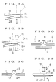
- Methods for joining parts of clean garments are various ones, as shown in Figs. 2A to 2F.
- Fig. 2A shows a method for placing first and second parts 1 and 2 one on top of the other, so that respective end portions are superimposed, and joining with heat bonding the above superimposed portions.
- Fig. 2B shows a method for superimposing respective end portions of first and second parts 1 and 2 after the end portions are made to be projected upwards, and joining with heat bonding the superimposed portions.
- Fig. 2C shows a method for superimposing respective end portions of first and second parts 1 and 2 after the end portions are made to be each turned down , and joining with heat bonding the superimposed portions.
- Fig. 2D shows a method for superimposing respective end portions of first and second parts 1 and 2 after only one of the end portions are made to be each turned down, and joining with heatbonding the superimposed portions.
- Fig. 2E shows a method for superimposing respective end portions of first and second parts 1 and 2 , and joining with heatbonding the superimposed portions.
- Fig. 2F shows a method for superimposing respective end portions of first and second parts 1 and 2 after the end portions are made to be projected upwards, and joining with heat bonding the superimposed portions as well as joining with heat bonding a reinforcement part 3 to first and second parts 1 and 2 including the above superimposed portions.
- a method of Fig. 2F has the effect that the joining strength of the product manufactured is increased, which method of Fig. 2F will be explained hereinafter in process order, based on Fig. 3A to 3E.
- Figure 4 shows an example of an apparatus for producing clean garments in accordance with the present invention, which apparatus is one for joining parts with super-sonic wave bonding.
- reference numeral 10 is a horn, 12 is an anvil.
- the horn 10 is a vibrator which is vibrated by super-sonic waves
- the anvil 12 is a pedestal on which an object, to be bonded with heat by using the above super-sonic waves, is placed.
- the horn 10 is vibrated to the vertical direction as shown with arrow C, by a super-sonic wave oscillator at the desired frequency.
- the anvil 12 may be rotatable to the clockwise direction as shown with arrow D, on the outer surface of which anvil 12 patterns P1 and P2 are formed.
- the anvil 12 is a knurled anvil.
- the object is composed of the first and second parts 1 and 2 in the opening state with the joining portion S as the central figure, and the reinforcement part 3 applied along the longitudinal direction of the joining portion S, extending over the first and second parts 1 and 2.
- the first and second parts 1 and 2 are placed on the anvil 12 with the reinforcement part 3 applied to them along the longitudinal direction of the joining portion S.
- the anvil 12 rotates in the direction as shown by arrow D, and accordingly the above object inserted between the horn 10 and the anvil 12 is carried in the direction as shown with arrow E.
- patterns P1 and P2 are formed on the first and second parts 1 and 2 with the joining portion S as the central figure, which patterns P1 and P2 are the same as the patterns P1 and P2 of the anvil 12.
- Fig 1. there are provided clean gagarments put on in the clean room comprising each part of right arm portion 10A etc. which is respectively made by synthetic textile, the unit of right front body 10C1, right back body 10D1, left front body 10C2 and left back body 10D2 joined with heat bonding, which unit is turned down on the position corresponding to the right and left ankles, turned down portions of which unit are joined with heat bonding, fasteners F which are each joined to said right and left front bodies 10C1 and 10C2, with heat bonding, right arm portion 10A and left arm portion 10B which are each joined to said unit with heat bonding, and are respectively turned down on the position corresponding to the right and left wrist, turned down portions of which arm portions 10A and 10B are joined with heat bonding, collar portion 10E which is joined to said unit with heat bonding, on the position corresponding to the neck; and patterns P1 and P2 which are each formed on the area including a joining portion S of said part
- each part made by synthetic textile is respectively joined with heat bonding.
- clean garments in accordance with the present invention have no hole through which a needle passes, and accordingly, dust cannot be released out from inside to outside.
- the present invention has the technical effect to increase airtightness of clean garments and to reduce the number of processes for producing them, by joining each part of them with heat bonding.
Landscapes
- Engineering & Computer Science (AREA)
- Mechanical Engineering (AREA)
- Textile Engineering (AREA)
- Health & Medical Sciences (AREA)
- General Health & Medical Sciences (AREA)
- Physical Education & Sports Medicine (AREA)
- Professional, Industrial, Or Sporting Protective Garments (AREA)
- Lining Or Joining Of Plastics Or The Like (AREA)
- Details Of Garments (AREA)
- Treatment Of Fiber Materials (AREA)
Abstract
Description
- The present invention relates to clean garments.
- More particularly, it relates to clean garments put on in the clean room of semiconductor manufacturing factory etc..
- Conventionally, it is well known that the products of various fields of industry are manufactured in the clean room.
- Especially, in the semiconductor manufacturing industry, a super clean room in the first class is used, wherein a particle having the size of submicron should be one in the air of 1 cubic foot.
- In a clean room in which such a high cleanness is desired, clean garments must be put on in order to remove pollution source of dust etc..
- The above clean garments should have airtight seam, in order to fulfill two functions of not releasing out dust from inside to outside and not releasing off dust from cloth of clean garments.
- The conventional clean garments, which must have airtight seam, has been produced with sewing thread, the problems of which clean garments are as follows.
- (1)Dust is released out through holes formed on cloth of clean garments.
That is to say, since the conventional clean garments has been produced with sewing thread, a hole is always formed on cloth of them at an interval of sticking a needle into cloth, through which hole a needle passes.
However, when the conventional clean garments with such a hole is put on, dust is released out through this hole.
Concequently, the clean room is polluted with dust. - (2)Waste thread is generated.
That is to say, when the conventional clean garments produced with sewing thread is put on, waste thread is generated, during putting on this clean garments.
Concequently, the clean room is polluted with waste thread.
Moreover, while the conventional clean garments produced with sewing thread is put on, sewing thread and cloth are rubbed together.
Concequently, since waste thread is generated, the clean room is polluted with it. - (3) It is necessary to use many processes.
- That is to say, as above-mentioned, since the conventional clean garments is produced with sewing thread, the desired sewing thread should be always used regarding one clean garments.
- Accordingly, it is necessary to be provided with processes of preparing sewing thread and checking quality of it etc..
- Concequently, it is necessary to use many processes related to sewing thread.
- As apparently from the above-mentioned items (1) to (3), the conventional clean garments have the problems that airtightness is low, and that processes for producing them are many in number.
- An object of the present invention is to increase airtightness of clean garments and to reduce the number of processes for producing them, by joining each part of them with heat bonding.
- The above-mentioned object can be achieved by clean garments put on in the clean room comprising each part of right arm portion etc. which is respectively made by synthetic textile, the unit of right front body, right back body, left front body and left back body joined with heat bond ing, which unit is turned down on the position corresponding to the right and left ankles, turned down portions of which unit are joined with heat bonding, fasteners which are each joined to said right and left front bodies and with heat bonding, right arm portion and left arm portion which are each joined to said unit with heat bonding, and are respectively turned down on the position corresponding to the right and left wrist, turned down portions of which arm portions and are joined with heat bonding, collar portion which is joined to said unit with heat bonding, on the position corresponding to the neck; and patterns and which are each formed on the area including a joining portion of said part, respectively consisting of a concave portion and, convex portions at both sides of the concave portion.
- Further features and advantages of the present invention will be apparent from the ensuring description with reference to the accompanying drawings, wherein:
- Fig. 1 is a drawing of an embodiment of the present invention;
- Figs. 2A to 2F are drawings of methods for joining parts of clean garments in accordance with the present invention;
- Figs. 3A to 3E are detailed drawings of a method for joining parts of clean garments in accordance with the present invention; and
- Fig. 4 is a drawing of an apparatus for joining parts of clean garments in accordance with the present invention.
- Figure 1 is a drawing of an embodiment of the present invention, wherein
reference numeral 10A shows right arm portion, 10B left arm portion, 10C1 right front body, 10C2 left front body, 10D1 right back body, 10D2 left back body, and 10E collar portion. - Clean garments as shown in Fig. 1 is put on in the clean room of semiconductor manufacturing factory etc..
- Generally, clean garments are divided broadly into separate type that a upper garment and a pair of trousers are separate, and overall type that they are overall in one unit.
- Clean garments as shown in Fig. 1 is the above overall type.
- Each part of the above
right arm portion 10A etc. is made by synthetic textile to be joined with heat bonding. - Moreover, Each part of the above
right arm portion 10A etc. is joined by means of bonding respective end portions with heat, joining portion of which part is shown with reference numeral S in Fig. 1. - End portions of
right arm portion 10A andleft arm portion 10B are joined with heat bonding, and they are turned down on the position corresponding to the right and left wrist, which portion turned down is joined with heat bonding. - Right front body 10C1 and right back body 10D1 are joined with heat bonding on the position corresponding to the right shoulder, right body side to leg outside, and right leg inside, respectively, as shown in Fig. 1.
- The unit of right front body 10C1 and right back body 10D1 joined in such a manner is turned down on the position corresponding to the right ankle, which portion turned down is joined with heat bonding, as well as it is joined to
right arm portion 10A with heat bonding. - On the other hand, left front body 10C2 and left back body 10D2 are joined with heat bonding on the position corresponding to the left shoulder, left body side to leg outside, and left leg inside, respectively, as shown in Fig. 1.
- The unit of left front body 10C2 and left back body 10D2 in such a manner is turned down on the position corresponding to the left ankle, which portion turned down is joined with heat bonding, as well as it is joined to
left arm portion 10B with heat bonding. - Moreover, as shown in Fig. 1, right back body 10D1 and left back body 10D2 are joined with heat bonding, on the position corresponding to the central portion of the back.
- In such an above manner,
right arm portion 10A,left arm portion 10B · · · of parts constituting clean garments become to the unity, to which unity of right front body 10C1, left front body 10C2, right back body 10D1 and left back body 10D2,collar portion 10E is joined with heat bonding, on the position corresponding to the neck. - On the position corresponding to the central portion of the breast to abdomen, fasteners F are each joined to right front body 10C1 and left front body 10C2, with heat bonding.
- When the fasteners F are opened, clean garments can be put on by taking both legs into it.
- As after-mentioned, concretly, patterns P1 etc. are formed on the area including the joining portion S, which patterns P1 etc. consist of a concave portion and, convex portions at both sides of the concave portion.
- The concave portion is thinner than the other portion and is formed in film, whereby the joined area has flexibility.
- Methods for joining parts of clean garments are various ones, as shown in Figs. 2A to 2F.
- Of
parts first part 1 and asecond part 2, in Figs. 2A to 2F. - Fig. 2A shows a method for placing first and
second parts - Fig. 2B shows a method for superimposing respective end portions of first and
second parts - Fig. 2C shows a method for superimposing respective end portions of first and
second parts - Fig. 2D shows a method for superimposing respective end portions of first and
second parts - Fig. 2E shows a method for superimposing respective end portions of first and
second parts - Fig. 2F shows a method for superimposing respective end portions of first and
second parts reinforcement part 3 to first andsecond parts - Of methods for joining with heat bonding as shown in Fig. 2A to 2F, a method of Fig. 2F has the effect that the joining strength of the product manufactured is increased, which method of Fig. 2F will be explained hereinafter in process order, based on Fig. 3A to 3E.
- (1)At first, the same sides of the first and
second parts end portions
That is to say, as shown in Fig.3A, the same sides 1B and 2B of the first andsecond parts
Thereafter, theend portions second parts - (2)Next, the
superimposed end portions
Taking the means of heat bonding as an example, there is an apparatus for joining parts as shown in Fig.4, said apparatus taking advantage of super-sonic waves.
That is to say, as shown in Fig.3B, aftersuperimposed end portions anvil 12, super-sonic wave vibration is applied to them to the vertical directions shown by arrow A, with ahorn 10 under constant pressure.
Accordingly, theend portions - (3)The above first and the
second parts end portions
That is to say, as shown in Fig.3C, with the joining portion S as the central figure, the first and thesecond parts
In this case, the joining portion S projects slightly upwards as shown in Fig.3C. - (4)A
reinforcement part 3 is applied to, extending over the first andsecond parts
That is to say, as shown Fig.3D, thereinforcement part 3 is applied to, extending over the first andsecond parts
Thisreinforcement part 3 may be made from the same material as the first andsecond parts
However, it is preferable that it is thinner than the first andsecond parts end portions - (5)Finally, the
reinforcement part 3 is made to join, via heat bonding, to the first andsecond parts - Concretly, as shown in Fig.3E, the first and
second parts reinforcement part 3 applied thereto, are placed on theanvil 12. - From
above parts horn 10 under constant pressure. - Thereby, not only are the first and
second parts reinforcement part 3 as shown Fig.3E. - Accordingly, the joining strength of the product manufactured has been increased.
- Figure 4 shows an example of an apparatus for producing clean garments in accordance with the present invention, which apparatus is one for joining parts with super-sonic wave bonding.
- In Fig.4,
reference numeral 10 is a horn, 12 is an anvil. - As is well known, the
horn 10 is a vibrator which is vibrated by super-sonic waves, and theanvil 12 is a pedestal on which an object, to be bonded with heat by using the above super-sonic waves, is placed. - The
horn 10 is vibrated to the vertical direction as shown with arrow C, by a super-sonic wave oscillator at the desired frequency. - The
anvil 12 may be rotatable to the clockwise direction as shown with arrow D, on the outer surface of whichanvil 12 patterns P1 and P2 are formed. - That is to say, the
anvil 12 is a knurled anvil. - By replacing the
anvil 12, it is possible to form via heat bonding the joining area with patterns in different designs. - Generally, after an object is inserted between the
horn 10 and theanvil 12, super-sonic wave vibration in the virtical direction is applied by thehorn 10 to the object under constant pressure, whereby heat bonding is carried out owing to the generation of heat. - Concequently, patterns P1 and P2 formed on the
anvil 12 appear on the object. - The above general explanation will be hereinafter described in detail based on an example as shown in Fig. 4.
- In Fig. 4, an object is inserted between the
horn 10 and theanvil 12. - The object is composed of the first and
second parts reinforcement part 3 applied along the longitudinal direction of the joining portion S, extending over the first andsecond parts - At first, the first and
second parts anvil 12 with thereinforcement part 3 applied to them along the longitudinal direction of the joining portion S. - Next, super-sonic wave vibration in the vertical direction C is applied by the
horn 10 to the object under constant pressure, whereby heat bonding is carried out owing to the generation of heat. - Meanwhile, the
anvil 12 rotates in the direction as shown by arrow D, and accordingly the above object inserted between thehorn 10 and theanvil 12 is carried in the direction as shown with arrow E. - Consequently, as shown in Fig. 4, patterns P1 and P2 are formed on the first and
second parts anvil 12. - As afore-mentioned, according to the present invention, as shown in Fig 1., there are provided clean gagarments put on in the clean room comprising each part of
right arm portion 10A etc. which is respectively made by synthetic textile, the unit of right front body 10C1, right back body 10D1, left front body 10C2 and left back body 10D2 joined with heat bonding, which unit is turned down on the position corresponding to the right and left ankles, turned down portions of which unit are joined with heat bonding, fasteners F which are each joined to said right and left front bodies 10C1 and 10C2, with heat bonding,right arm portion 10A andleft arm portion 10B which are each joined to said unit with heat bonding, and are respectively turned down on the position corresponding to the right and left wrist, turned down portions of which armportions collar portion 10E which is joined to said unit with heat bonding, on the position corresponding to the neck; and patterns P1 and P2 which are each formed on the area including a joining portion S of said part, respectively consisting of a concave portion and, convex portions at both sides of the concave portion. - According to the above constitution, each part made by synthetic textile, is respectively joined with heat bonding.
- Hence, clean garments in accordance with the present invention have no hole through which a needle passes, and accordingly, dust cannot be released out from inside to outside.
- Concequently, the clean room is not polluted with dust.
- Next, since clean garments in accordance with the present invention are produced by not using sewing thread, waste thread is not generated during putting on this clean garments.
- Concequently, the clean room is not polluted with waste thread.
- Moreover, since clean garments in accordance with the present invention are produced without processes related to sewing thread, and are produced without limit by only one heat bonding apparatus, the number of processes for producing them has been reduced.
- That is to say, the present invention has the technical effect to increase airtightness of clean garments and to reduce the number of processes for producing them, by joining each part of them with heat bonding.
Claims (2)
- Clean garments put on in the clean room comprising:
each part of right arm portion (10A) etc. which is respectively made by synthetic textile;
the unit of right front body (10C1), right back body (10D1), left front body (10C2) and left back body (10D2) joined with heat bonding, which unit is turned down on the position corresponding to the right and left ankles, turned down portions of which unit are joined with heat bonding;
fasteners (F) which are each joined to said right and left front bodies (10C1) and (10C2), with heat bonding;
right arm portion (10A) and left arm portion (10B) which are each joined to said unit with heat bonding, and are respectively turned down on the position corresponding to the right and left wrist, turned down portions of which arm portions (10A) and (10B) are joined with heat bonding;
collar portion (10E) which is joined to said unit with heat bonding, on the position corresponding to the neck; and
patterns (P1 and P2) which are each formed on the area including a joining portion (S) of said part, respectively consisting of a concave portion and, convex portions at both sides of the concave portion. - Clean garments according to claim 1,
wherein said part is joined each other with heat bonding by a super-sonic wave apparatus having horn (10) and anvil (12), on outer surface of which anvil (12) said patterns (P1 and P2) are formed.
Applications Claiming Priority (2)
| Application Number | Priority Date | Filing Date | Title |
|---|---|---|---|
| JP7022314A JPH08199409A (en) | 1995-01-16 | 1995-01-16 | Dust-free garment |
| JP22314/95 | 1995-01-16 |
Publications (2)
| Publication Number | Publication Date |
|---|---|
| EP0721745A2 true EP0721745A2 (en) | 1996-07-17 |
| EP0721745A3 EP0721745A3 (en) | 1996-12-27 |
Family
ID=12079277
Family Applications (1)
| Application Number | Title | Priority Date | Filing Date |
|---|---|---|---|
| EP95104585A Withdrawn EP0721745A3 (en) | 1995-01-16 | 1995-03-28 | Clothing for clean rooms |
Country Status (3)
| Country | Link |
|---|---|
| EP (1) | EP0721745A3 (en) |
| JP (1) | JPH08199409A (en) |
| KR (1) | KR970061128A (en) |
Cited By (9)
| Publication number | Priority date | Publication date | Assignee | Title |
|---|---|---|---|---|
| FR2798565A1 (en) * | 1999-09-17 | 2001-03-23 | Licences En Ville | Garment of woven fabric has layers joined together with strip of thermofusible material to make pleats or folds for buttonholes |
| FR2828998A1 (en) * | 2001-09-03 | 2003-03-07 | Evelyne Altounian | Fabric edge assembly procedure, especially for garment shoulder strap, consists of welding edges together and covering with reinforcing layer |
| FR2850250A1 (en) * | 2003-01-27 | 2004-07-30 | Lee Sara Corp | Method for edge to edge assembling of textile pieces comprises sticking adhesive tape adjoining edges to textile edges to hold them together then shaving stuck adjoining edges and overlapping tape on textile edges and flattening |
| EP1491105A1 (en) * | 2003-06-27 | 2004-12-29 | W.L. GORE & ASSOCIATES GmbH | Welded microseam |
| FR2873545A1 (en) * | 2004-07-29 | 2006-02-03 | Salomon Sa | Sports garment is made from stretch fabric with welded seams that are turned outwards and covered by reinforcing strips |
| WO2006018548A3 (en) * | 2004-07-29 | 2006-03-30 | Salomon Sa | Method for assembling fabric panels and product obtainable by said mehtod |
| WO2007126287A1 (en) * | 2006-05-02 | 2007-11-08 | Korea Institute Of Industrial Technology | Manufacture and apparatus for safety garments using ultrasound fusion |
| CN102605602A (en) * | 2011-01-24 | 2012-07-25 | 麦西皮熨衣部股份公司 | Simplified method for making an impermeable joining on three-layer or bi-layer fabric materials |
| FR2977825A1 (en) * | 2011-07-15 | 2013-01-18 | Faurecia Innenraum Sys Gmbh | METHOD OF APPLYING A DECORATIVE STITCH BETWEEN TWO PORTIONS OF A THERMOPLASTIC FINISHING LAYER FOR A COMPOSITE PART AND TOOL FOR PERFORMING SUCH A METHOD |
Families Citing this family (5)
| Publication number | Priority date | Publication date | Assignee | Title |
|---|---|---|---|---|
| JP2005226173A (en) * | 2004-02-10 | 2005-08-25 | Phoenix:Kk | Apparel and method of manufacturing apparel |
| US8435617B2 (en) * | 2006-08-17 | 2013-05-07 | W. L. Gore & Associates, Inc. | Stitchless seam system for joining laminates |
| KR101047864B1 (en) * | 2008-01-10 | 2011-07-15 | (주)티 에스 에이 콜렉션 | Fabric Connection and Connection Method |
| KR100973199B1 (en) * | 2009-07-27 | 2010-07-30 | 황길연 | Dustproof clothing |
| JP2017218703A (en) * | 2016-06-09 | 2017-12-14 | アツギ株式会社 | Non-sewing stretch knitted garment and manufacturing method thereof |
Family Cites Families (6)
| Publication number | Priority date | Publication date | Assignee | Title |
|---|---|---|---|---|
| DE1250273B (en) * | 1963-04-04 | |||
| FR2468321A1 (en) * | 1979-11-02 | 1981-05-08 | Dispovet | Mfg. protective clothing from nonwoven synthetic fabrics - using flat panels folded for welding in one cycle |
| FR2515487A1 (en) * | 1981-10-30 | 1983-05-06 | Delta Protection | Panel patterns for making disposable combination over:garments - shaped to minimise stress on nonwoven fabric beneath the crutch |
| US4938817A (en) * | 1988-12-30 | 1990-07-03 | Kappler Safety Group | Method of forming bonded seams of spunbonded polyolefin fabric and cleanroom garments including such seams |
| CA2101833A1 (en) * | 1992-12-14 | 1994-06-15 | Kimberly-Clark Worldwide, Inc. | Stretchable meltblown fabric with barrier properties |
| US5509142A (en) * | 1993-06-30 | 1996-04-23 | Kimberly-Clark Corporation | Raised arm coveralls |
-
1995
- 1995-01-16 JP JP7022314A patent/JPH08199409A/en active Pending
- 1995-03-28 EP EP95104585A patent/EP0721745A3/en not_active Withdrawn
- 1995-12-15 KR KR1019950050342A patent/KR970061128A/en not_active Withdrawn
Cited By (17)
| Publication number | Priority date | Publication date | Assignee | Title |
|---|---|---|---|---|
| FR2798565A1 (en) * | 1999-09-17 | 2001-03-23 | Licences En Ville | Garment of woven fabric has layers joined together with strip of thermofusible material to make pleats or folds for buttonholes |
| FR2828998A1 (en) * | 2001-09-03 | 2003-03-07 | Evelyne Altounian | Fabric edge assembly procedure, especially for garment shoulder strap, consists of welding edges together and covering with reinforcing layer |
| EP1293137A1 (en) * | 2001-09-03 | 2003-03-19 | Evelyne Altounian | Suspender manufacturing method |
| FR2850250A1 (en) * | 2003-01-27 | 2004-07-30 | Lee Sara Corp | Method for edge to edge assembling of textile pieces comprises sticking adhesive tape adjoining edges to textile edges to hold them together then shaving stuck adjoining edges and overlapping tape on textile edges and flattening |
| WO2004075673A1 (en) * | 2003-01-27 | 2004-09-10 | Sara Lee Corporation | Method for the butt joining of two textile pieces |
| US7828925B2 (en) | 2003-01-27 | 2010-11-09 | Hbi Branded Apparel Enterprises, Llc | Method for the butt joining of two textile pieces |
| CN100508805C (en) * | 2003-06-27 | 2009-07-08 | W.L.戈尔有限公司 | Welded microseam |
| EP1714566A3 (en) * | 2003-06-27 | 2007-09-05 | W.L.Gore & Associates Gmbh | Microseam |
| EP1714567A3 (en) * | 2003-06-27 | 2007-09-19 | W.L. GORE & ASSOCIATES GmbH | Microseam |
| WO2005000055A1 (en) * | 2003-06-27 | 2005-01-06 | W.L.Gore & Associates Gmbh | Welded microseam |
| EP1491105A1 (en) * | 2003-06-27 | 2004-12-29 | W.L. GORE & ASSOCIATES GmbH | Welded microseam |
| FR2873545A1 (en) * | 2004-07-29 | 2006-02-03 | Salomon Sa | Sports garment is made from stretch fabric with welded seams that are turned outwards and covered by reinforcing strips |
| WO2006018548A3 (en) * | 2004-07-29 | 2006-03-30 | Salomon Sa | Method for assembling fabric panels and product obtainable by said mehtod |
| EP2243387A3 (en) * | 2004-07-29 | 2012-08-15 | Salomon S.A.S. | Textile article |
| WO2007126287A1 (en) * | 2006-05-02 | 2007-11-08 | Korea Institute Of Industrial Technology | Manufacture and apparatus for safety garments using ultrasound fusion |
| CN102605602A (en) * | 2011-01-24 | 2012-07-25 | 麦西皮熨衣部股份公司 | Simplified method for making an impermeable joining on three-layer or bi-layer fabric materials |
| FR2977825A1 (en) * | 2011-07-15 | 2013-01-18 | Faurecia Innenraum Sys Gmbh | METHOD OF APPLYING A DECORATIVE STITCH BETWEEN TWO PORTIONS OF A THERMOPLASTIC FINISHING LAYER FOR A COMPOSITE PART AND TOOL FOR PERFORMING SUCH A METHOD |
Also Published As
| Publication number | Publication date |
|---|---|
| JPH08199409A (en) | 1996-08-06 |
| KR970061128A (en) | 1997-09-12 |
| EP0721745A3 (en) | 1996-12-27 |
Similar Documents
| Publication | Publication Date | Title |
|---|---|---|
| JPH0578973A (en) | Method for joining nonwoven fabric | |
| EP0891252A4 (en) | Costumes with semi-rigid fabric components and method for manufacture of same | |
| GB1600133A (en) | Dielectric heat welding supported polymeric leathercloth | |
| KR20040040403A (en) | Wrinkle free garment and method of manufacture | |
| US4561126A (en) | Folded sleeved garment | |
| JPH08199409A (en) | Dust-free garment | |
| EP0385611A3 (en) | Dye impermeable, distortion resistant textile identification products | |
| US3710394A (en) | Method of making a reversible garment | |
| US5575007A (en) | Reversible necktie and method for making same | |
| JP2005200778A (en) | Joining structure of sewn part of water-working wear, and joining method for the same | |
| US4757559A (en) | Method for forming half and full-felled seams | |
| JPH03161565A (en) | Embroidering method and product produced thereby | |
| US4653122A (en) | Method for automated construction of pants | |
| KR100234884B1 (en) | How to sew clothes | |
| JPH0450304A (en) | Bonding between clothing and material | |
| Hayes | Joining techniques for high-performance apparel | |
| JPH0732484A (en) | Manufacturing method of conveyor belt | |
| US3585951A (en) | F producing a stitched seam | |
| US3720958A (en) | Necktie and method of making same | |
| JPH072564Y2 (en) | girdle | |
| JPH09137374A (en) | Fusion-bonding of cloth piece with ultrasonic spot fusion-bonding machine and receiving jig for ultrasonic spot fusion-bonding machine used for performing the method | |
| JP3012979B2 (en) | Shoulder pad | |
| JPS61160401A (en) | Production of kimono | |
| JPH0734308A (en) | Welding method and welding tool | |
| JPH0987911A (en) | Front body of upper garment |
Legal Events
| Date | Code | Title | Description |
|---|---|---|---|
| PUAI | Public reference made under article 153(3) epc to a published international application that has entered the european phase |
Free format text: ORIGINAL CODE: 0009012 |
|
| AK | Designated contracting states |
Kind code of ref document: A2 Designated state(s): DE FR GB |
|
| PUAL | Search report despatched |
Free format text: ORIGINAL CODE: 0009013 |
|
| AK | Designated contracting states |
Kind code of ref document: A3 Designated state(s): DE FR GB |
|
| 17P | Request for examination filed |
Effective date: 19970627 |
|
| STAA | Information on the status of an ep patent application or granted ep patent |
Free format text: STATUS: THE APPLICATION IS DEEMED TO BE WITHDRAWN |
|
| 17Q | First examination report despatched |
Effective date: 20000224 |
|
| 18D | Application deemed to be withdrawn |
Effective date: 19991001 |