EP0721648B1 - Switch - Google Patents
Switch Download PDFInfo
- Publication number
- EP0721648B1 EP0721648B1 EP94927712A EP94927712A EP0721648B1 EP 0721648 B1 EP0721648 B1 EP 0721648B1 EP 94927712 A EP94927712 A EP 94927712A EP 94927712 A EP94927712 A EP 94927712A EP 0721648 B1 EP0721648 B1 EP 0721648B1
- Authority
- EP
- European Patent Office
- Prior art keywords
- switch
- led
- electro
- initial position
- mechanical
- Prior art date
- Legal status (The legal status is an assumption and is not a legal conclusion. Google has not performed a legal analysis and makes no representation as to the accuracy of the status listed.)
- Expired - Lifetime
Links
Images

Classifications
-
- H—ELECTRICITY
- H01—ELECTRIC ELEMENTS
- H01H—ELECTRIC SWITCHES; RELAYS; SELECTORS; EMERGENCY PROTECTIVE DEVICES
- H01H11/00—Apparatus or processes specially adapted for the manufacture of electric switches
- H01H11/0006—Apparatus or processes specially adapted for the manufacture of electric switches for converting electric switches
- H01H11/0012—Apparatus or processes specially adapted for the manufacture of electric switches for converting electric switches for converting normally open to normally closed switches and vice versa
Definitions
- the present invention relates to an electro-mechanical switch.
- the switch has two light-emitting diodes, namely a green LED which is illuminated when the switch is connected to a power supply, and a yellow LED which is illuminated only while a switching operation is occurring.
- a green LED which is illuminated when the switch is connected to a power supply
- a yellow LED which is illuminated only while a switching operation is occurring.
- DE-U-8602553.8 describes a cylindrical proximity switch having one or more LEDs and a rotary switch, actuable by a setscrew or a screw-driver, and connected to a flexible printed circuit board.
- the present invention provides an electro-mechanical switch as defined in Claim 1 hereinafter.
- the switch incorporates set means being a mode selector so that the switch can be installed in the appropriate mode (or its mode can be changed after installation) quickly and easily compared to the prior art, and without disruption to the other terminal connections.
- the switch may comprise any one or more of the features as set out in dependent Claims 2 to 5 hereinafter
- Figures 1 and 2 shows a limit switch 1 of the type having a green LED 2 to indicate when the switch is powered and a yellow LED 3 to indicate whenever the switch is actuated (the LED's not being visible in Figures 1 or 2).
- Switch 1 has a mode selector 4 with two electro-mechanical microswitches 5 and 6 and a slider 7 with cam surfaces 8 and 9 engageable against the levers 10 and 11 of microswitches 5 and 6.
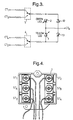
- LEDs 2, 3 and microswitches 5 and 6 are connected to a pcb circuit as shown in Figure 3, the circuit including protection diodes 12 and 13 to prevent the LEDs being damaged if the limit switch is wired up incorrectly, circuit terminals CT 1 , CT 2 , CT 3 , CT 4 and CT A being linked in use to switch terminals ST 1 , ST 2 , ST 3 , ST 4 and ST A in a manner to be described later, with Figure 4 showing how switch terminals ST 1 , ST 2 , ST 3 , ST 4 , and ST A of limit switch 1 are wired up to the external circuit in which switch 1 operates.
- the limit switch 1 must be connected so that terminals ST 1 and ST 3 are the live side of the switch (i.e. input) and terminals ST 2 and ST 4 are the isolated side (i.e. output).
- the switch terminals are hard wired to the two microswitches 5 and 6, one microswitch for the input terminals ST 1 and ST 3 and the second for the output terminals ST 2 and ST 4 .
- These microswitches are operated by bias cams 8 and 10, to allow their outputs to be connected to either the "normally open” terminals ST 1 , ST 2 or "normally closed” terminals ST 3 , ST 4 of the limit switch 1.
- Microswitches 5 and 6 connect the LED's diagonally across the limit switch 1 with the green LED 2 always being connected to the input side, and the yellow LED 3 always to the output.
- the mode selector 4 is such that the switch in the initial position is "normally open” i.e. microswitches 5, 6 are set up as shown in Figure 3, the green LED 2 is connected via CT 1 to terminal ST 1 and is hence live with green LED 2 illuminated, while the yellow LED 3 is connected via CT 4 to terminal ST 4 and hence the yellow LED 3 is not illuminated.
- the green LED 2 is lit.
- the "normally closed” circuit should be used for a signal supply. Only when the switch has been activated or switched will terminal CT 4 (and hence the yellow LED 3) be connected to the signal supply and therefore yellow LED 3 be lit. Thus the green LED 2 is lit permanently and the yellow LED 3 goes on and off as the switch is operated and then returned to the initial position.
- the microswitches are set up in the opposite way from that shown by in Figure 3, green LED 2 is connected via CT 3 to ST 3 which is live so that green LED 2 is illuminated, while yellow LED is connected, via CT 2 , to ST 2 which is isolated so that yellow LED 3 is not illuminated. Only when the switch has been activated or switched will terminal CT 2 (and hence the yellow LED 3) be connected to the signal supply and therefore yellow LED 3 be lit.
Landscapes
- Engineering & Computer Science (AREA)
- Manufacturing & Machinery (AREA)
- Switch Cases, Indication, And Locking (AREA)
- Push-Button Switches (AREA)
Description
Claims (6)
- An electro-mechanical switch (1) having two stable positions, one of which is the initial position of the switch and the other is the position of the switch when actuated, the switch having LED means (2) to indicate that there is a connection to a power supply and LED means (3) to indicate when the switch (1) is being actuated, the switch characterised by:means (4-9) to set, by a single manual operation, a pair of electro-mechanical microswitches (5, 6) whereby the switch (1) is in either of the stable positions as the initial position of the switch (1).
- A switch according to Claim 1, characterised in that the set means (4-9), in operation, effects a change of the electrical connection(s) of the supply-indicator means (2) and/or the actuation-indicator means (3) within the switch (1).
- A switch according to Claim 1 or 2, characterised in that the set means (4-9) comprises cam means (8, 9) movable between one location, in which one of the stable positions constitutes the initial position of the switch, and another location, in which the other of the stable positions constitutes the initial position of the switch (1).
- A switch according to any preceding Claim, characterised in that the set means (4-9) operates the pair of electro-mechanical microswitches (5,6) located between the terminals of the electro-mechanical switch (1) and the indicator means (2, 3).
- A switch according to any preceding Claim, characterised in that an output of at least one of the indicator means (2, 3) is connected to a return or a ground terminal (CTA).
- A switch according to any preceding Claim, characterised in that the set means (4-9) comprises a slider (7) operable adjacent and in a direction parallel, to one exterior side of the switch (1).
Applications Claiming Priority (3)
| Application Number | Priority Date | Filing Date | Title |
|---|---|---|---|
| GB9319885 | 1993-09-27 | ||
| GB939319885A GB9319885D0 (en) | 1993-09-27 | 1993-09-27 | Switch |
| PCT/GB1994/002084 WO1995009430A1 (en) | 1993-09-27 | 1994-09-26 | Switch |
Publications (2)
| Publication Number | Publication Date |
|---|---|
| EP0721648A1 EP0721648A1 (en) | 1996-07-17 |
| EP0721648B1 true EP0721648B1 (en) | 1999-06-16 |
Family
ID=10742576
Family Applications (1)
| Application Number | Title | Priority Date | Filing Date |
|---|---|---|---|
| EP94927712A Expired - Lifetime EP0721648B1 (en) | 1993-09-27 | 1994-09-26 | Switch |
Country Status (4)
| Country | Link |
|---|---|
| EP (1) | EP0721648B1 (en) |
| DE (1) | DE69419164T2 (en) |
| GB (1) | GB9319885D0 (en) |
| WO (1) | WO1995009430A1 (en) |
Family Cites Families (2)
| Publication number | Priority date | Publication date | Assignee | Title |
|---|---|---|---|---|
| EP0098894B1 (en) * | 1982-07-16 | 1986-10-08 | Square D Starkstrom GmbH | Electric commutation device, in particular a contactor |
| DE8602553U1 (en) * | 1986-01-31 | 1986-04-03 | Siemens AG, 1000 Berlin und 8000 München | Cylindrical proximity switch |
-
1993
- 1993-09-27 GB GB939319885A patent/GB9319885D0/en active Pending
-
1994
- 1994-09-26 DE DE69419164T patent/DE69419164T2/en not_active Expired - Fee Related
- 1994-09-26 EP EP94927712A patent/EP0721648B1/en not_active Expired - Lifetime
- 1994-09-26 WO PCT/GB1994/002084 patent/WO1995009430A1/en not_active Ceased
Also Published As
| Publication number | Publication date |
|---|---|
| GB9319885D0 (en) | 1993-11-10 |
| WO1995009430A1 (en) | 1995-04-06 |
| DE69419164T2 (en) | 1999-12-23 |
| DE69419164D1 (en) | 1999-07-22 |
| EP0721648A1 (en) | 1996-07-17 |
Similar Documents
| Publication | Publication Date | Title |
|---|---|---|
| US5244409A (en) | Molded connector with embedded indicators | |
| US7285721B1 (en) | Modular terminal device | |
| US5062807A (en) | Lighted electrical connector permitting multi directional viewing | |
| US5348047A (en) | Valve arrangement | |
| US3944316A (en) | Electrical connectors with keying means | |
| EP0830702B1 (en) | Circuit breaker accessory module | |
| US6842123B1 (en) | Electromechanical switching device and emergency shut-off and communication system utilizing same | |
| AU8049294A (en) | Pushbutton electrical switch assembly | |
| US6787717B2 (en) | Controller switch assembly | |
| DK1484511T3 (en) | Linkage module for activating an electric valve drive in a fluid technical valve arrangement | |
| US7213932B1 (en) | Electrical device with lamp module | |
| US4949222A (en) | Electrical apparatus combination | |
| EP0740843B1 (en) | Manually actuatable integrated control module and method of making same | |
| US20030112571A1 (en) | Self-diagnostic solid state relay | |
| EP0721648A1 (en) | Switch | |
| US5277622A (en) | Electric connecting device for pilot valves in a valve array | |
| EP2724434A2 (en) | Integral module with lighted faceplate display | |
| US6744340B2 (en) | Switch with magnetically coupled rocker armature | |
| MX9700894A (en) | Interlock assembly for a fusible switch. | |
| MXPA01010558A (en) | Plate-frame for electric and electronic mechanisms. | |
| JP4516192B2 (en) | Solenoid valve manifold | |
| US4954671A (en) | Connectible switching device | |
| KR200363458Y1 (en) | Multi-legged power connectors with multiple circuit breakers | |
| EP0774380B1 (en) | Improved-wiring device for controlling the emergency lights in motor vehicles | |
| KR200229121Y1 (en) | ON, OFF check switch |
Legal Events
| Date | Code | Title | Description |
|---|---|---|---|
| PUAI | Public reference made under article 153(3) epc to a published international application that has entered the european phase |
Free format text: ORIGINAL CODE: 0009012 |
|
| 17P | Request for examination filed |
Effective date: 19960315 |
|
| AK | Designated contracting states |
Kind code of ref document: A1 Designated state(s): DE ES FR GB IT |
|
| 17Q | First examination report despatched |
Effective date: 19970523 |
|
| GRAG | Despatch of communication of intention to grant |
Free format text: ORIGINAL CODE: EPIDOS AGRA |
|
| GRAG | Despatch of communication of intention to grant |
Free format text: ORIGINAL CODE: EPIDOS AGRA |
|
| GRAH | Despatch of communication of intention to grant a patent |
Free format text: ORIGINAL CODE: EPIDOS IGRA |
|
| GRAH | Despatch of communication of intention to grant a patent |
Free format text: ORIGINAL CODE: EPIDOS IGRA |
|
| GRAA | (expected) grant |
Free format text: ORIGINAL CODE: 0009210 |
|
| ITF | It: translation for a ep patent filed | ||
| AK | Designated contracting states |
Kind code of ref document: B1 Designated state(s): DE ES FR GB IT |
|
| PG25 | Lapsed in a contracting state [announced via postgrant information from national office to epo] |
Ref country code: ES Free format text: THE PATENT HAS BEEN ANNULLED BY A DECISION OF A NATIONAL AUTHORITY Effective date: 19990616 |
|
| REF | Corresponds to: |
Ref document number: 69419164 Country of ref document: DE Date of ref document: 19990722 |
|
| ET | Fr: translation filed | ||
| PLBE | No opposition filed within time limit |
Free format text: ORIGINAL CODE: 0009261 |
|
| STAA | Information on the status of an ep patent application or granted ep patent |
Free format text: STATUS: NO OPPOSITION FILED WITHIN TIME LIMIT |
|
| 26N | No opposition filed | ||
| REG | Reference to a national code |
Ref country code: GB Ref legal event code: IF02 |
|
| PGFP | Annual fee paid to national office [announced via postgrant information from national office to epo] |
Ref country code: IT Payment date: 20080913 Year of fee payment: 15 Ref country code: FR Payment date: 20080904 Year of fee payment: 15 |
|
| PGFP | Annual fee paid to national office [announced via postgrant information from national office to epo] |
Ref country code: GB Payment date: 20080808 Year of fee payment: 15 |
|
| PGFP | Annual fee paid to national office [announced via postgrant information from national office to epo] |
Ref country code: DE Payment date: 20080930 Year of fee payment: 15 |
|
| GBPC | Gb: european patent ceased through non-payment of renewal fee |
Effective date: 20090926 |
|
| REG | Reference to a national code |
Ref country code: FR Ref legal event code: ST Effective date: 20100531 |
|
| PG25 | Lapsed in a contracting state [announced via postgrant information from national office to epo] |
Ref country code: FR Free format text: LAPSE BECAUSE OF NON-PAYMENT OF DUE FEES Effective date: 20090930 Ref country code: DE Free format text: LAPSE BECAUSE OF NON-PAYMENT OF DUE FEES Effective date: 20100401 |
|
| PG25 | Lapsed in a contracting state [announced via postgrant information from national office to epo] |
Ref country code: GB Free format text: LAPSE BECAUSE OF NON-PAYMENT OF DUE FEES Effective date: 20090926 |
|
| PG25 | Lapsed in a contracting state [announced via postgrant information from national office to epo] |
Ref country code: IT Free format text: LAPSE BECAUSE OF NON-PAYMENT OF DUE FEES Effective date: 20090926 |