EP0721618B1 - Process for accelerated rule evaluation in a fuzzy inference processor and device for carrying it out - Google Patents
Process for accelerated rule evaluation in a fuzzy inference processor and device for carrying it out Download PDFInfo
- Publication number
- EP0721618B1 EP0721618B1 EP94926781A EP94926781A EP0721618B1 EP 0721618 B1 EP0721618 B1 EP 0721618B1 EP 94926781 A EP94926781 A EP 94926781A EP 94926781 A EP94926781 A EP 94926781A EP 0721618 B1 EP0721618 B1 EP 0721618B1
- Authority
- EP
- European Patent Office
- Prior art keywords
- input
- address
- output
- rule
- rule segment
- Prior art date
- Legal status (The legal status is an assumption and is not a legal conclusion. Google has not performed a legal analysis and makes no representation as to the accuracy of the status listed.)
- Expired - Lifetime
Links
Images

Classifications
-
- G—PHYSICS
- G06—COMPUTING; CALCULATING OR COUNTING
- G06N—COMPUTING ARRANGEMENTS BASED ON SPECIFIC COMPUTATIONAL MODELS
- G06N7/00—Computing arrangements based on specific mathematical models
- G06N7/02—Computing arrangements based on specific mathematical models using fuzzy logic
- G06N7/04—Physical realisation
-
- Y—GENERAL TAGGING OF NEW TECHNOLOGICAL DEVELOPMENTS; GENERAL TAGGING OF CROSS-SECTIONAL TECHNOLOGIES SPANNING OVER SEVERAL SECTIONS OF THE IPC; TECHNICAL SUBJECTS COVERED BY FORMER USPC CROSS-REFERENCE ART COLLECTIONS [XRACs] AND DIGESTS
- Y10—TECHNICAL SUBJECTS COVERED BY FORMER USPC
- Y10S—TECHNICAL SUBJECTS COVERED BY FORMER USPC CROSS-REFERENCE ART COLLECTIONS [XRACs] AND DIGESTS
- Y10S706/00—Data processing: artificial intelligence
- Y10S706/90—Fuzzy logic
Definitions
- a single rule has a condition part with a partial condition for each input variable and a subsequent part with an assignment of a linguistic value for the respective output variable.
- a rule evaluation consists in principle of checking whether the subconditions of each rule for all individual input variables are fulfilled or not, and, according to a respective rule, of assigning a specific linguistic value to the output variables.
- the object of the invention is to provide a method and a device for its implementation, which enable accelerated rule evaluation in a fuzzy inference processor.
- Claims 3 to 6 relate to advantageous configurations of the device.
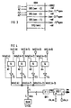
- FIG. 1 shows a block diagram which, in addition to a device according to the invention, contains a knowledge base memory KBM, a control decoder REDEC, a control evaluation circuit RE with a read / write memory RAM and a fuzzification circuit FUZ.
- the device according to the invention has a masking device SONAR (screening of not active rules) with an address memory DPRAM. Because of the small chip area requirement, the address memory DPRAM preferably consists of a read / write memory with a separate data output and data input (dual ported RAM), but can also consist, for example, of an appropriately switched shift register.
- the masking device SONAR also contains a counter CNT_a for the output pointer and a counter CNT_e for an input pointer.
- a relative address ad for a respective control segment word and a delayed relative address adrv for the respective control segment word are generated in the masking device SONAR.
- the delayed relative address adrv can be written into the address memory DPRAM depending on a control signal zw.
- the relative address ad and the delayed relative address adrv are each 6 bits wide.
- a counter CNT_f for addressing the respective input variables is located in the address formation unit ADR.
- the addressing unit ADR receives information such as the start address KBD2, the number apev of the block segment words and the number of nev of the input variables and forms the absolute address address, which here is 15 bits wide, for example.
- the start address KBD2, the number apev and the number nev come from the knowledge base memory KBM; this relationship is indicated by dashed lines in FIG. 1.
- the knowledge base memory KBM addressed by the absolute address, supplies numbers re for the rules corresponding to the respective control segments for linguistic values of the input variables belonging to the control segment word.
- numbers ne from the fuzzification circuit FUZ are compared with the numbers re from the knowledge base memory KBM and hit signals are formed.
- hit signals are formed.
- four numbers re with the respective resolution a LW are compared with the numbers ne, the numbers ne also having the resolution a LW , and four hit signals 1 hit wide are generated therefrom.
- the fuzzification circuit FUZ is supplied with sharp input values E (1).
- a control signal zw for the masking device SONAR can be formed in the device HITW for recognizing control segment words that are still relevant.
- the device HITW in addition to the hit signals hit, also has hit signals hitp for previous input variables can be supplied and, in addition to the control signal zw, new hit signals heat, in which the hit signals hit are now taken into account, can be formed.
- the hit signals hitp of the previous input variables can be read out from a read / write memory and the new hit signals can be written back to it, addressing the read / write memory advantageously being used by the delayed relative address adrv from the masking device SONAR.
- the hit signals can be heated with advantage in the read / write memory RAM of the control evaluation RE by increasing the word width, here enlarged by 4 bits, saved.
- the hit signals it would be conceivable for the hit signals to be stored hot in a separate read / write memory and for separate addressing to take place.
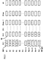
- rules R1 ... R5 ... Rk ... Rnr-4 ... Rnr are shown line by line in FIG. 2, wherein for each of the input variables EV1, EV2 ... EV1 ... EVnev-1 , EVnev and a control segment RS is provided for the output variable AV.
- the control segments for the input variables contain numbers for predetermined linguistic values of the respective input variables in the condition part of the respective rule and the control segments for the output variables contain numbers for linguistic values of the output variables in the following part of the respective rule.
- control segments of the input variables EV1 are processed, the control segments belonging to the input variables EV1 being checked to determine whether the partial conditions of the rules defined by them are fulfilled or not. If a rule segment of a rule is not met, the entire rule is not met, since all of them in the condition part Logically AND-linked input variables that appear in the rule are represented by exactly one linguistic value or exactly one control segment.
- control elements for the input variable EV1 and the rules R1 ... R4 and Rnr-3 are identified by crosses in FIG. 2, which mean that these control segments are not fulfilled.
- the rule segments valid for the input variable EV2 and the rules Rnr-3 ... Rnr are marked as not fulfilled. If, for example, control segment words with only one control segment are used, the rules R1 ... R4 and Rnr-3 are excluded when processing the rules for the input variable EV2.
- control segment words RW1 ... RWapev each with four control segments, are used, as shown in Figure 1 as an example, if four control segments are processed in parallel, then rules R1 ...
- rule R4 can be disregarded when processing input variables EV, since all control segments of control segment word RW1 do not apply, however, rule Rnr-3 must be taken into account when processing input variable EV2, since only the control segment determined by input variable EV1 and rule Rnr-3 does not apply within control segment word RWapev. Rule segment words with a lower one The number of control segments generally brings about a higher saving effect with regard to the method according to the invention.
- SRS control segments
- the start address is also the beginning of the sentence SRS (nev-3), the beginning of the sentence SRS (nev-2) is determined by adding the relative address (nev-3) * apev to determine the input variables, the beginning of the sentence SRS (nev- 1) by adding the relative address (nev-2) * apev to the start address and the start for the set SRS (nev) by adding the relative address (nev-1) * apev to determine the input variables to the start address KBD2.
- Addressing within the sets of control segments takes place by adding the respective relative address ad to address individual control segment words.
- Exemplary are an input pointer EZ and an output pointer AZ, which point to control segment words in the set of control segments SRS (nev-3) and pointers EZ 'and AZ', which point to control segment words in the set SRS (nev-2).
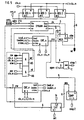
- FIG 4 shows a detailed circuit of the device HITW for the detection of still relevant control segment words, in which, for example, four hit signals hit (l, k) ... hit (l, k + 3)) with hit signals hitp from the read / write memory RAM, the for example, 4 * 64 bits are processed, the control signal zw being generated.
- a hit signal hit (l, k) is given to a first input of an AND circuit A1, the hit signal hit (l, k + 1) to a first input of an AND circuit A2, the hit signal hit to a first input of an AND circuit A3 ( l, k + 2) and a first input of the AND circuit A4, the hit signal hit (l, k + 3).
- a second entrance the AND circuit A1 carries a hit signal hitp (l, k), a second input of the AND circuit A2 a hit signal hitp (l, k + 1), a second input of the AND circuit A3 a hit signal hitp (l, k + 2) and a second input of the AND circuit A4 a hit signal hitp (l, k + 3).
- the hit signals hitp (l, k) ... hitp (l, k + 3) can be read out of the RAM by means of a bidirectional data bus, with the hit signals hit (l, k) ... hit (l, k + 3) AND-linked and can be written back to the read / write memory RAM via driver circuits T1 ...
- T4 driver signal hitz (l, k) ... hitz (l, k + 3). Because of the given signal conditions, no feedback or oscillations occur and there is no need to decouple the hitp and heat signals by holding elements. Since the hit signals are each only 1 bit wide, there is a minimum combination of only one AND circuit.
- the four 1-bit hit signals hitz (l, k) ... hitz (l, k + 3) are combined in an OR circuit OR1 to form a signal zwp which can be fed to an input of a register REG1, at whose output the control signal is removable.
- Register REG1 works according to the so-called master-slave principle, master M receiving a clock signal cls_m and slave S receiving a clock signal cls_s.
- FIG. 5 shows a detailed circuit of the masking device SONAR, which has an address memory DPRAM in the form of a dual-ported RAM, the data input Din of which receives the delayed relative address adrv, which is obtained from the relative address ad for the respective one by three registers REG2 ...
- Control segment word can be formed, the input address input A of which can be fed into an output signal cne of the counter CNT_e for the input pointer, the data output D out of which is connected to a zero input of a multiplexer MUX, the output address input of which can be supplied with an output signal cna of the counter CNT_a for the output pointer and whose Output address input is connected to a one input of the multiplexer MUX, whose output the relative address ad leads for the respective control segment word.
- a write signal wr which enables the delayed relative address adrv to be written into the address memory DPRAM, can be formed as a function of the control signal zw, the control signal zw a first input of an AND circuit A5, a clock signal cls_s a second input of the AND circuit A5 Clock signal clk_m can be fed to a third input of AND circuit A5 and a write activation signal enw to a fourth input of AND circuit A5.
- a read signal rd is connected to the output of an AND circuit A6, the first input of which can be supplied with the clock signal clk_m, a second input with the clock signal cls_m and a third input with a read activation signal enr.
- the clock signal clk_m has twice the clock frequency than the signal cls_s.
- the counter CNT_a works according to the master-slave principle, can be loaded to a predetermined value load-a as soon as a load activation signal loaden_a is present, and count as soon as a counter activation signal cnten_a is present.
- the clock input for the master carries the signal cls_s and the input for the slave S carries the clock cls_m.
- the counter CNT_e to which a load signal load_e, a load activation signal loaden_e and a counter activation signal cnten_e can be supplied, the latter signal corresponding to the control signal zw.
- the master connection M and the slave connection S are wired the same way for both meters.
- an identity comparator circuit E is provided, the first input of which is connected to the output of the counter CNT_a and the second input of which can be supplied with the number apev of the control segment words for an input variable.
- a holding element LAT is provided in the masking device SONAR, at the input of which the output signal cne of the counter for the input pointer is located and the output of which carries an output signal ees which corresponds to the value for the last input pointer position before a change to the next input variable.
- the holding element LAT is clocked by a clock signal ls and by a set signal set can be set.
- control signal zw 1 or zw is 0, the relative address ad required to read out the current control segment word is written back or not.
- the set or reset write signal wr ensures this.
- the count of the input counter available at the end of the processing of a set of control segments or an input variable is written into the holding element LAT by activating the signal ls. This value serves as the end mark for the counter reading of the output counter in the subsequent cycle.
- the output signal ees of the holding element LAT can be fed to a last input of the small comparator COMP, at the second input of which the output cna of the output counter CNA_a is located.
- the rule evaluation is in the stage of processing a set of rule segments and the output signal stop2 of the small comparator COMP is zero.
- stop2 is 1 is 1, in all cycles, except in the first one, a control unit is informed whether the processing of a set of control segments is finished or not. If, on the other hand, all control segment words of the first input variable have been processed, the first stop signal stop1 goes to 1.
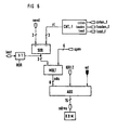
- the address formation unit ADR contains the counter CNT_f, a subtractor SUB, a multiplier MULT and an adder ADD and optionally a NOR circuit NOR.
- the counter CNT_f consists, for example, of a 3 bit forward counter which can be precharged to one via a load input load_f if a load activation signal loaden_f is present and which counts if a counter activation signal cnten_f is present.
- the counter CNT_f delivers at its output a signal z1 for the negative input of the sub-emitter SUB.
- the number nev of the input variables is fed to the plus input of the subtractor SUB, the number nev likewise having 3 bits, for example.
- the output signal of the subtractor SUB is, for example, 3 bits wide and is fed to an input of the multiplier MULT, the further input of which receives, for example, a 6 bit wide signal for the number apev of the control segment words of an input variable.
- a relative start address ada for addressing a memory area containing the control segment words of the respective input variables is formed and fed to a first input of the adder circuit ADD, the relative address ada having a word length of 8 bits, for example.
- a second The start address KBD2 is input to the adder circuit and the relative address ad for addressing the respective control segment word is fed to a third input of the adder circuit, and the absolute address address for addressing the knowledge base memory KBM is present at the output of the adder ADD, which has a word length of 15 bits, for example .
- the counter CNT_f is activated every time all valid control segment words of a respective input variable have been processed and the stop signals stopl or stop2 are set to one in the SONAR masking device.
- NOR circuit NOR can be provided, with the aid of which the output signal of the subtractor circuit SUB can be linked bit by bit to form a signal load to determine the last input variable.
- the signal last is 1, the stop signal stop is 1 or the stop signal stop2 is 1, the processing of the total nev input variables is ended.
- the relative address ada for addressing the memory area belonging to the respective input variable is generated in such a way that a first input variable addresses, a first value for a maximum input pointer position of the respective previous input variable equal to the number apev of all control segment words RW1 ... RWapev set because there is no previous input variable for the first input variable, and the address memory DPRAM is loaded with relative addresses of all control segment words.
- the input pointer EZ and the output pointer AZ are set in such a way that a first cell of the address memory, that is to say a first control segment word of the respective input variable, is addressed.
- the respective relative address ad for addressing Control segment words are read out from the memory cell of the address memory addressed by the output pointer and then the output pointer position is switched on by one cell of the address memory, that is to say by one control segment word.
- the absolute address address of a respective control segment word is formed from the respective relative address ad for addressing control segment words, the start address KBD2 and the relative start address ada, an individual control segment corresponding to a linguistic value of the respective input variable in the condition part of the respective rule.
- a fifth step of the method according to the invention the respective relative address ad for addressing a respective control segment word is only written back into the cell of the address memory addressed by the input pointer and then the input pointer position is only advanced by one cell of the address memory if at least one of the addresses addressed by the respective one Control segment word defined conditions for the respective input variable is fulfilled.
- steps three to five are repeated until the value of the output pointer has reached the value of the maximum input pointer position of the respectively preceding input variable and then the respective value of the maximum input pointer position of the respectively previous input variable is set to the value of the respective last current input pointer position and the relative address ada for addressing the respective input variable is increased so that the next input variable is addressed.
- Steps 2 to 6 are carried out until all nev input variables have been processed.
Abstract
Description
Eine einzelne Regel weist einen Bedingungsteil mit je einer Teilbedingung für jede Eingangsvariable und einen Folgeteil mit einer Zuweisung eines linguistischen Wertes für die jeweilige Ausgangsvariable auf. Eine Regelauswertung besteht im Prinzip darin, zu überprüfen, ob die Teilbedingungen einer jeden Regel für alle einzelnen Eingangsvariablen erfüllt sind oder nicht, und, gemäß einer jeweiligen Regel, der Ausgangsvariablen einen bestimmten linguistischen Wert zuzuordnen.A single rule has a condition part with a partial condition for each input variable and a subsequent part with an assignment of a linguistic value for the respective output variable. A rule evaluation consists in principle of checking whether the subconditions of each rule for all individual input variables are fulfilled or not, and, according to a respective rule, of assigning a specific linguistic value to the output variables.
Dokument IEEE INTERNATIONAL CONFERENCE ON FUZZY SYSTEMS, 8-12 March 1992, SAN DIEGO, CA., USA, 1992, IEEE, NEW YORK, NY, USA. Seiten 537-544, H. IKEDA ET AL. 'A Fuzzy Inference Coprocessor using a flexible Active-Rule-Driven Architecture' offenbart ein Fuzzy-Inferenz-System wobei aktive Regeln (Regeln deren IF-Teil-Grade nicht alle Null sind für gegebener Eingangsdaten) am Anfang der Fuzzy-Inferenz aufgefunden werden können.Document IEEE INTERNATIONAL CONFERENCE ON FUZZY SYSTEMS, March 8-12, 1992, SAN DIEGO, CA., USA, 1992, IEEE, NEW YORK, NY, USA. Pages 537-544, H. IKEDA ET AL. 'A Fuzzy Inference Coprocessor using a flexible Active-Rule-Driven Architecture' discloses a fuzzy inference system whereby active rules (rules whose IF part degrees are not all zero for given input data) can be found at the beginning of fuzzy inference .
Die Aufgabe der Erfindung liegt nun darin, ein Verfahren und eine Vorrichtung zu dessen Durchführung anzugeben, die in einem Fuzzy-Inference-Prozessor eine beschleunigte Regelauswertung ermöglichen.The object of the invention is to provide a method and a device for its implementation, which enable accelerated rule evaluation in a fuzzy inference processor.
Die Aufgabe wird hinsichtlich des Verfahrens durch die im Patentanspruch 1 angegebenen Merkmale und hinsichtlich der Vorrichtung zu dessen Durchführung durch die Merkmale des vom Patentanspruch 1 abhängigen Patentanspruch 2 gelöst.The object is achieved with regard to the method by the features specified in
Die Ansprüche 3 bis 6 beziehen sich auf vorteilhafte Ausbildungen der Vorrichtung.
Die Erfindung wird nachfolgend anhand der Zeichnung näher erläutert. Dabei zeigt
Figur 1- ein Übersichtsschaltbild mit der erfindungsgemäßen Vorrichtung und weitere Einheiten eines Fuzzy-Inference-Prozessors,
Figur 2- eine Darstellung zur Erläuterung des erfindungsgemäßen Verfahrens,
Figur 3- eine Darstellung zur Erläuterung der Speicherorganisation in einem Adreßspeicher der erfindungsgemäßen Vorrichtung,
Figur 4- eine Detailschaltung einer in
Figur 1 enthaltenen Einrichtung zur Erkennung betroffener Regelsegmentworte, - Figur 5
- eine Detailschaltung einer in
Figur 1 enthaltenen Ausblendeinrichtung und Figur 6- eine Detailschaltung einer in
Figur 1 enthaltenen Adreßbildungseinheit.
- Figure 1
- 2 shows an overview circuit diagram with the device according to the invention and further units of a fuzzy inference processor,
- Figure 2
- a representation to explain the method according to the invention,
- Figure 3
- 2 shows a representation to explain the memory organization in an address memory of the device according to the invention,
- Figure 4
- 2 shows a detailed circuit of a device for recognizing affected control segment words contained in FIG. 1,
- Figure 5
- a detailed circuit of a blanking device contained in Figure 1 and
- Figure 6
- a detailed circuit of an address formation unit contained in Figure 1.
In Figur 1 ist ein Blockschaltbild gezeigt, das neben einer erfindungsgemäßen Vorrichtung, einen Wissensbasisspeicher KBM, einen Regeldecoder REDEC, eine Regelauswertungsschaltung RE mit einem Schreib/Lese-Speicher RAM und eine Fuzzifikationsschaltung FUZ enthält. Die erfindungsgemäße Vorrichtung weist eine Ausblendeinrichtung SONAR (screening of not active rules) mit einem Adreßspeicher DPRAM auf. Der Adreßspeicher DPRAM besteht wegen des geringen Chipflächenbedarfs vorzugsweise aus einem Schreib/Lese-Speicher mit einem getrennten Datenausgang und Dateneingang (dual ported RAM), kann aber beispielsweise auch aus einem entsprechend geschalteten Schieberegister bestehen. Die Ausblendeinrichtung SONAR enthält darüber hinaus einen Zähler CNT_a für den Ausgabezeiger und einen Zähler CNT_e für einen Eingabezeiger. In der Ausblendeinrichtung SONAR wird eine Relativadresse ad für ein jeweiliges Regelsegmentwort und eine verzögerte Relativadresse adrv für das jeweilige Regelsegmentwort erzeugt. Die verzögerte Relativadresse adrv ist dabei abhängig von einem Steuersignal zw in den Adreßspeicher DPRAM einschreibbar. Sind beispielsweise wie hier 64 Regelsegmentworte vorgesehen und zu adressieren, so ist die Relativadresse ad und die verzögerte Relativadresse adrv jeweils 6 Bit breit.FIG. 1 shows a block diagram which, in addition to a device according to the invention, contains a knowledge base memory KBM, a control decoder REDEC, a control evaluation circuit RE with a read / write memory RAM and a fuzzification circuit FUZ. The device according to the invention has a masking device SONAR (screening of not active rules) with an address memory DPRAM. Because of the small chip area requirement, the address memory DPRAM preferably consists of a read / write memory with a separate data output and data input (dual ported RAM), but can also consist, for example, of an appropriately switched shift register. The masking device SONAR also contains a counter CNT_a for the output pointer and a counter CNT_e for an input pointer. A relative address ad for a respective control segment word and a delayed relative address adrv for the respective control segment word are generated in the masking device SONAR. The delayed relative address adrv can be written into the address memory DPRAM depending on a control signal zw. For example, like here are 64 rule segment words provided and to be addressed, the relative address ad and the delayed relative address adrv are each 6 bits wide.
In der Adreßbildungseinheit ADR befindet sich ein Zähler CNT_f zur Adressierung der jeweiligen Eingangsvariablen. Die Adressierungseinheit ADR erhält neben der Relativadresse ad Angaben wie die Startadresse KBD2, die Anzahl apev der Blocksegmentworte und die Anzahl der nev der Eingangsvariablen und bildet daraus die absolute Adresse adres, die beispielsweise hier 15 Bit breit ist. Die Startadresse KBD2, die Anzahl apev und die Anzahl nev stammen aus dem Wissensbasisspeicher KBM; dieser Zusammenhang ist in Figur 1 gestrichelt angedeutet.A counter CNT_f for addressing the respective input variables is located in the address formation unit ADR. In addition to the relative address ad, the addressing unit ADR receives information such as the start address KBD2, the number apev of the block segment words and the number of nev of the input variables and forms the absolute address adres, which here is 15 bits wide, for example. The start address KBD2, the number apev and the number nev come from the knowledge base memory KBM; this relationship is indicated by dashed lines in FIG. 1.
Der durch die absolute Adresse adres adressierte Wissensbasisspeicher KBM liefert zu den der jeweiligen Regelsegmenten entsprechenden Regeln Nummern re für linguistische Werte der zum Regelsegmentwort gehörenden Eingangsvariablen.The knowledge base memory KBM, addressed by the absolute address, supplies numbers re for the rules corresponding to the respective control segments for linguistic values of the input variables belonging to the control segment word.
In der Regeldecoderschaltung RDEC werden Nummern ne aus der Fuzzifikationsschaltung FUZ mit den Nummern re aus dem Wissensbasisspeicher KBM verglichen und Treffersignale gebildet. In dem hier verwendeten Beispiel werden vier Nummern re mit der jeweiligen Auflösung aLW jeweils mit den Nummern ne verglichen, wobei die Nummern ne ebenfalls die Auflösung aLW besitzen, und daraus vier 1 Bit breite Treffe signale hit erzeugt. Zur Erzeugung der Nummern ne werden der Fuzzifikationsschaltung FUZ scharfe Eingangswerte E(1) zugeführt. In der Einrichtung HITW zur Erkennung weiterhin relevanter Regelsegmentworte ist abhängig von den Treffersignalen hit ein Steuersignal zw für die Ausblendeinrichtung SONAR bildbar.In the control decoder circuit RDEC, numbers ne from the fuzzification circuit FUZ are compared with the numbers re from the knowledge base memory KBM and hit signals are formed. In the example used here, four numbers re with the respective resolution a LW are compared with the numbers ne, the numbers ne also having the resolution a LW , and four
Bei einer vorteilhaften Ausgestaltung der erfindungsgemäßen Vorrichtung sind der Einrichtung HITW, neben den Treffersignalen hit, auch Treffersignale hitp für bisherige Eingangsvariable zuführbar und daraus neben dem Steuersignal zw, neue Treffersignale hitz, in denen nun auch die Treffersignale hit berücksichtigt sind, bildbar. Die Treffersignale hitp der bisherigen Eingangsvariablen sind dabei aus einem Schreib/Lese-Speicher auslesbar und die neuen Treffersignale hitz in diesem zurückschreibbar, wobei eine Adressierung des Schreib/Lese-Speichers vorteilhafterweise durch die verzögerte Relativadresse adrv aus der Ausblendeinrichtung SONAR verwendet wird. Da die Regelauswertungsschaltung re ohnehin einen Schreib/Lese-Speicher für die Zwischenspeicherung von Minima enthält, der vorteilhafterweise ebenfalls durch die verzögerte Relativadresse adrv adressierbar ist, können die Treffersignale hitz mit Vorteil im Schreib/Lese-Speicher RAM der Regelauswertung RE durch Vergrößerung der Wortbreite, hier um 4 Bit vergrößert, gespeichert werden. Alternativ hierzu wäre denkbar, daß die Treffersignale hitz in einem separaten Schreib/Lese-Speicher gespeichert werden und eine getrennte Adressierung erfolgt.In an advantageous embodiment of the device according to the invention, in addition to the hit signals hit, the device HITW also has hit signals hitp for previous input variables can be supplied and, in addition to the control signal zw, new hit signals heat, in which the hit signals hit are now taken into account, can be formed. The hit signals hitp of the previous input variables can be read out from a read / write memory and the new hit signals can be written back to it, addressing the read / write memory advantageously being used by the delayed relative address adrv from the masking device SONAR. Since the control evaluation circuit re already contains a read / write memory for the intermediate storage of minima, which advantageously can also be addressed by the delayed relative address adrv, the hit signals can be heated with advantage in the read / write memory RAM of the control evaluation RE by increasing the word width, here enlarged by 4 bits, saved. As an alternative to this, it would be conceivable for the hit signals to be stored hot in a separate read / write memory and for separate addressing to take place.
Zur Erläuterung des erfindungsgemäßen Verfahrens sind in Figur 2 Regeln R1 ... R5 ... Rk ... Rnr-4 ... Rnr zeilenweise dargestellt, wobei für jede der Eingangsvariablen EV1, EV2 ... EV1 ... EVnev-1, EVnev sowie für die Ausgangsvariable AV ein Regelsegment RS vorgesehen ist. Die Regelsegmente für die Eingangsvariablen enthalten dabei Nummern für vorgegebene linguistische Werte der jeweiligen Eingangsvariablen im Bedingungsteil der jeweiligen Regel und die Regelsegmente für die Ausgangsvariablen enthalten Nummern für linguistische Werte der Ausgangsvariablen im Folgeteil der jeweiligen Regel. Von wesentlicher Bedeutung für das erfindungsgemäße Verfahren ist dabei, daß zunächst alle Regelsegmente der Eingangsvariablen EV1 abgearbeitet werden, wobei die zur Eingangsvariablen EV1 gehörigen Regelsegmente daraufhin überprüft werden, ob die durch sie definierten Teilbedingungen der Regeln erfüllt sind oder nicht. Ist ein Regelsegment einer Regel nicht erfüllt, so ist die gesamte Regel nicht erfüllt, da alle im Bedingungsteil einer Regel vorkommenden logisch UND-verknüpften Eingangsvariablen durch je genau einen linguistischen Wert bzw. genau ein Regelsegment vertreten sind. Nachdem alle Regelsegmente der Eingangsvariablen EV1 abgearbeitet sind, erfolgt eine Umschaltung auf die nächste Eingangsvariable EV2 und es werden nach dem erfindungsgemäßen Verfahren im allgemeinen nicht mehr alle Regelsegmente der Eingangsvariablen EV2 abgearbeitet, sondern nur noch diejenigen, bei denen das Regelsegmentwort der vorhergehenden Eingangsvariable EV1, das im einfachsten Fall aus einem einzigen Regelsegment besteht, erfüllt war. Bei der Eingangsvariablen EV1 werden nur noch die Regelsegmente überprüft, bei denen die Eingangsvariable EV1-1 ... EV1 alle erfüllt waren. Dies wird entsprechend fortgesetzt bis die Eingangsvariable EV1 der Eingangsvariablen EVnev entspricht.To explain the method according to the invention, rules R1 ... R5 ... Rk ... Rnr-4 ... Rnr are shown line by line in FIG. 2, wherein for each of the input variables EV1, EV2 ... EV1 ... EVnev-1 , EVnev and a control segment RS is provided for the output variable AV. The control segments for the input variables contain numbers for predetermined linguistic values of the respective input variables in the condition part of the respective rule and the control segments for the output variables contain numbers for linguistic values of the output variables in the following part of the respective rule. It is essential for the method according to the invention that first all control segments of the input variables EV1 are processed, the control segments belonging to the input variables EV1 being checked to determine whether the partial conditions of the rules defined by them are fulfilled or not. If a rule segment of a rule is not met, the entire rule is not met, since all of them in the condition part Logically AND-linked input variables that appear in the rule are represented by exactly one linguistic value or exactly one control segment. After all control segments of input variable EV1 have been processed, a switchover to the next input variable EV2 takes place and, according to the method according to the invention, it is generally no longer all control segments of input variable EV2 that are processed, but only those in which the control segment word of the previous input variable EV1, that in the simplest case consists of a single rule segment, was fulfilled. With the input variable EV1, only those control segments are checked for which the input variables EV1-1 ... EV1 were all fulfilled. This continues accordingly until the input variable EV1 corresponds to the input variable EVnev.
Beispielhaft sind in Figur 2 die Regelsemente für die Eingangsvariable EV1 und die Regeln R1 ... R4 sowie Rnr-3 durch Kreuze gekennzeichnet, die bedeuten, daß diese Regelsegmente nicht erfüllt sind. Entsprechenderweise sind die für die Eingangsvariable EV2 und die Regeln Rnr-3 ... Rnr geltenden Regelsegmente als nicht erfüllt gekennzeichnet. Werden beispielsweise Regelsegmentworte mit nur einem Regelsegment verwendet, so scheiden die Regeln R1 ... R4 sowie Rnr-3 bei der Abarbeitung der Regeln für die Eingangsvariable EV2 aus. Werden jedoch, wie auch in Figur 1 beispielhaft dargestellt, Regelsegmentworte RW1 ... RWapev mit jeweils vier Regelsegmenten verwendet, erfolgt also eine Parallelverarbeitung von vier Regelsegmenten, so können die Regeln R1 ... R4 bei der Abarbeitung der Eingangsvariablen EV unberücksichtigt bleiben, da alle Regelsegmente des Regelsegmentwortes RW1 nicht zutreffen, die Regel Rnr-3 muß hingegen bei der Bearbeitung der Eingangsvariablen EV2 berücksichtigt werden, da nur das durch die Eingangsvariable EV1 und die Regel Rnr-3 bestimmte Regelsegment innerhalb des Regelsegmentwortes RWapev nicht zutrifft. Regelsegmentworte mit einer geringeren Anzahl von Regelsegmenten bringen im allgemeinen einen höheren Einsparungseffekt bezüglich des erfindungsgemäßen Verfahrens.As an example, the control elements for the input variable EV1 and the rules R1 ... R4 and Rnr-3 are identified by crosses in FIG. 2, which mean that these control segments are not fulfilled. Correspondingly, the rule segments valid for the input variable EV2 and the rules Rnr-3 ... Rnr are marked as not fulfilled. If, for example, control segment words with only one control segment are used, the rules R1 ... R4 and Rnr-3 are excluded when processing the rules for the input variable EV2. However, if control segment words RW1 ... RWapev, each with four control segments, are used, as shown in Figure 1 as an example, if four control segments are processed in parallel, then rules R1 ... R4 can be disregarded when processing input variables EV, since all control segments of control segment word RW1 do not apply, however, rule Rnr-3 must be taken into account when processing input variable EV2, since only the control segment determined by input variable EV1 and rule Rnr-3 does not apply within control segment word RWapev. Rule segment words with a lower one The number of control segments generally brings about a higher saving effect with regard to the method according to the invention.
In Figur 3 ist ein Ausschnitt des Wissensbasisspeichers KBM ab der Startadresse KBD2 für nev = 4 dargestellt. Für die Eingangsvariable EV1 ist ein Satz von Regelsegmenten SRS (nev), für die Eingangsvariable EV2 ein Satz SRS (nev-1), für die Eingangsvariable EV3 ein Satz von Regelsegmenten SRS (nev-2) und für die Eingangsvariable EV4 ein Satz von Regelsegmenten SRS (nev-3) gezeigt. Die Startadresse ist zugleich der Beginn des Satzes SRS (nev-3), der Beginn des Satzes SRS (nev-2) wird durch Addition der Relativadresse (nev-3) * apev zur Festlegung der Eingangsvariablen, der Beginn des Satzes SRS (nev-1) durch Addition der Relativadresse (nev-2) * apev zur Startadresse und der Beginn für den Satz SRS (nev) durch Addition der Relativadresse (nev-1) * apev zur Festlegung der Eingangsvariablen zur Startadresse KBD2 festgelegt. Eine Adressierung innerhalb der Sätze von Regelsegmenten erfolgt durch Addition der jeweiligen Relativadresse ad zur Adressierung einzelner Regelsegmentwörter. Beispielhaft sind ein Eingangszeiger EZ und ein Ausgangszeiger AZ, die auf Regelsegmentwörtern im Satz von Regelsegmenten SRS (nev-3) und Zeiger EZ' und AZ', die auf Regelsegmentworte im Satz SRS (nev-2) zeigen, eingetragen.FIG. 3 shows a section of the knowledge base memory KBM from the start address KBD2 for nev = 4. For the input variable EV1 there is a set of control segments SRS (nev), for the input variable EV2 a set of SRS (nev-1), for the input variable EV3 a set of control segments SRS (nev-2) and for the input variable EV4 a set of control segments SRS (nev-3) shown. The start address is also the beginning of the sentence SRS (nev-3), the beginning of the sentence SRS (nev-2) is determined by adding the relative address (nev-3) * apev to determine the input variables, the beginning of the sentence SRS (nev- 1) by adding the relative address (nev-2) * apev to the start address and the start for the set SRS (nev) by adding the relative address (nev-1) * apev to determine the input variables to the start address KBD2. Addressing within the sets of control segments takes place by adding the respective relative address ad to address individual control segment words. Exemplary are an input pointer EZ and an output pointer AZ, which point to control segment words in the set of control segments SRS (nev-3) and pointers EZ 'and AZ', which point to control segment words in the set SRS (nev-2).
Figur 4 zeigt eine Detailschaltung der Einrichtung HITW zur Erkennung weiterhin relevanter Regelsegmentwörter, bei der beispielsweise vier Treffersignale hit (l, k) ... hit (l, k+3)) mit Treffersignalen hitp aus dem Schreib/Lese-Speicher RAM, der beispielsweise 4 * 64 Bit umfaßt, verarbeitet sind, wobei das Steuersignal zw erzeugt wird. Hierzu wird einem ersten Eingang einer UND-Schaltung Al ein Treffersignal hit (l, k), einem ersten Eingang einer UND-Schaltung A2 das Treffersignal hit (l, k+1), einem ersten Eingang einer UND-Schaltung A3 das Treffersignal hit (l, k+2) und einem ersten Eingang der UND-Schaltung A4 das Treffersignal hit (l, k+3) zugeführt. Ein zweiter Eingang der UND-Schaltung Al führt ein Treffersignal hitp (l, k), ein zweiter Eingang der UND-Schaltung A2 ein Treffersignal hitp (l, k+1), ein zweiter Eingang der UND-Schaltung A3 ein Treffersignal hitp (l, k+2) und ein zweiter Eingang der UND-Schaltung A4 ein Treffersignal hitp (l, k+3). Die Treffersignale hitp (l, k) ... hitp (l, k+3) können über einen bidirektionalen Datenbus aus dem Schreib/Lese-Speicher RAM ausgelesen, mit den Treffersignalen hit (l, k) ... hit (l, k+3) UND-verknüpft und über Treiberschaltungen T1 ... T4 als Treibersignal hitz (l, k) ... hitz (l, k+3) in den Schreib/Lese-Speicher RAM zurückgeschrieben werden. Aufgrund der gegebenen Signalverhältnisse treten keine Rückkopplungen bzw. Schwingungen auf und es kann eine Entkopplung der Signale hitp und hitz durch Halteglieder entfallen. Da die Treffersignale jeweils nur 1 Bit breit sind, besteht eine Minimumverknüpfung nur aus einer UND-Schaltung. Die vier 1 Bit breiten Treffersignale hitz (l, k) ... hitz (l, k+3) werden in einer ODER-Schaltung OR1 zu einem Signal zwp verknüpft, das einem Eingang eines Registers REG1 zuführbar ist, an dessen Ausgang das Steuersignal zw entnehmbar ist. Das Register REG1 arbeitet nach dem sogenannten Master-Slave-Prinzip, wobei der Master M ein Taktsignal cls_m und der Slave S ein Taktsignal cls_s erhält.Figure 4 shows a detailed circuit of the device HITW for the detection of still relevant control segment words, in which, for example, four hit signals hit (l, k) ... hit (l, k + 3)) with hit signals hitp from the read / write memory RAM, the for example, 4 * 64 bits are processed, the control signal zw being generated. For this purpose, a hit signal hit (l, k) is given to a first input of an AND circuit A1, the hit signal hit (l, k + 1) to a first input of an AND circuit A2, the hit signal hit to a first input of an AND circuit A3 ( l, k + 2) and a first input of the AND circuit A4, the hit signal hit (l, k + 3). A second entrance the AND circuit A1 carries a hit signal hitp (l, k), a second input of the AND circuit A2 a hit signal hitp (l, k + 1), a second input of the AND circuit A3 a hit signal hitp (l, k + 2) and a second input of the AND circuit A4 a hit signal hitp (l, k + 3). The hit signals hitp (l, k) ... hitp (l, k + 3) can be read out of the RAM by means of a bidirectional data bus, with the hit signals hit (l, k) ... hit (l, k + 3) AND-linked and can be written back to the read / write memory RAM via driver circuits T1 ... T4 as driver signal hitz (l, k) ... hitz (l, k + 3). Because of the given signal conditions, no feedback or oscillations occur and there is no need to decouple the hitp and heat signals by holding elements. Since the hit signals are each only 1 bit wide, there is a minimum combination of only one AND circuit. The four 1-bit hit signals hitz (l, k) ... hitz (l, k + 3) are combined in an OR circuit OR1 to form a signal zwp which can be fed to an input of a register REG1, at whose output the control signal is removable. Register REG1 works according to the so-called master-slave principle, master M receiving a clock signal cls_m and slave S receiving a clock signal cls_s.
Figur 5 zeigt eine Detailschaltung der Ausblendeinrichtung SONAR, die einen Adreßspeicher DPRAM in Form eines Dual-ported-RAM aufweist dessen Dateneingang Din die verzögerte Relativadresse adrv erhält, die durch drei in Reihe geschaltete Register REG2 ... REG4 aus der Relativadresse ad für das jeweilige Regelsegmentwort bildbar ist, dessen Eingabeadreßeingang Ain ein Ausgangssignal cne des Zählers CNT_e für den Eingabezeiger zuführbar ist, dessen Datenausgang Dout mit einem Null-Eingang eines Multiplexers MUX verbunden ist, dessen Ausgabeadreßeingang ein Ausgangssignal cna des Zählers CNT_a für den Ausgabezeiger zuführbar ist und dessen Ausgabeadreßeingang mit einem Eins-Eingang des Multiplexers MUX verbunden ist, dessen Ausgang die Relativadresse ad für das jeweilige Regelsegmentwort führt. Ein Schreibsignal wr, das das Einschreiben der verzögerten Relativadresse adrv in den Adreßspeicher DPRAM ermöglicht, ist in Abhängigkeit des Steuersignals zw bildbar, wobei das Steuersignal zw einen ersten Eingang einer UND-Schaltung A5, ein Taktsignal cls_s einem zweiten Eingang der UND-Schaltung A5 ein Taktsignal clk_m einem dritten Eingang der UND-Schaltung A5 und ein Schreibaktivierungssignal enw einem vierten Eingang der UND-Schaltung A5 zuführbar ist. Ein Lesesignal rd liegt am Ausgang einer UND-Schaltung A6, deren erster Eingang mit dem Taktsignal clk_m, ein zweiter Eingang mit dem Taktsignal cls_m und ein dritter Eingang mit einem Leseaktivierungssignal enr versorgbar ist. Das Taktsignal clk_m hat dabei die doppelte Taktfrequenz als das Signal cls_s. Der Zähler CNT_a arbeitet nach dem Master-Slave-Prinzip, kann auf einen vorgegebenen Wert load-a geladen werden, sobald ein Ladeaktivierungssignal loaden_a anliegt, und zählen, sobald ein Zähleraktivierungssignal cnten_a anliegt. Der Takteingang für den Master führt das Signal cls_s und der Eingang für den Slave S führt den Takt cls_m. Entsprechendes gilt für den Zähler CNT_e, dem ein Ladesignal load_e, ein Ladeaktivierungssignal loaden_e und ein Zähleraktivierungssignal cnten_e zuführbar sind wobei letzteres Signal dem Steuersignal zw entspricht. Der Master-Anschluß M und der Slave-Anschluß S sind bei beiden Zählern gleich beschaltet. Zur Erzeugung eines ersten Stopsignals stopl ist eine Identitätsvergleicherschaltung E vorgesehen, deren erster Eingang mit dem Ausgang des Zählers CNT_a verbunden ist und dessen zweitem Eingang die Anzahl apev der Regelsegmentworte für eine Eingangsvariable zuführbar ist. Ferner ist in der Ausblendeinrichtung SONAR ein Halteglied LAT vorgesehen, an dessen Eingang das Ausgangssignal cne des Zählers für den Eingabezeiger liegt und dessen Ausgang ein Ausgangssignal ees führt, dem der Wert für die jeweils letzte Eingabezeigerposition vor einem Wechsel zur nächsten Eingangsvariablen entspricht. Das Halteglied LAT ist durch ein Taktsignal ls getaktet und durch ein Setzsignal set setzbar. Zur Erzeugung eines zweiten Stopsignals stop2 ist ein Kleiner-Komparator (COMP) mit der Vergleichsbedingung a < b vorgesehen, dessen a-Eingang das Signal ees, dessen b-Eingang das Ausgangssignal cna des Zählers CNT_a für den Ausgabezeiger erhält und an dessen Ausgang das zweite Stopsignal stop2=1 bildbar ist, wenn eine jeweilige Eingangsvariable abgearbeitet ist.FIG. 5 shows a detailed circuit of the masking device SONAR, which has an address memory DPRAM in the form of a dual-ported RAM, the data input Din of which receives the delayed relative address adrv, which is obtained from the relative address ad for the respective one by three registers REG2 ... REG4 connected in series Control segment word can be formed, the input address input A of which can be fed into an output signal cne of the counter CNT_e for the input pointer, the data output D out of which is connected to a zero input of a multiplexer MUX, the output address input of which can be supplied with an output signal cna of the counter CNT_a for the output pointer and whose Output address input is connected to a one input of the multiplexer MUX, whose output the relative address ad leads for the respective control segment word. A write signal wr, which enables the delayed relative address adrv to be written into the address memory DPRAM, can be formed as a function of the control signal zw, the control signal zw a first input of an AND circuit A5, a clock signal cls_s a second input of the AND circuit A5 Clock signal clk_m can be fed to a third input of AND circuit A5 and a write activation signal enw to a fourth input of AND circuit A5. A read signal rd is connected to the output of an AND circuit A6, the first input of which can be supplied with the clock signal clk_m, a second input with the clock signal cls_m and a third input with a read activation signal enr. The clock signal clk_m has twice the clock frequency than the signal cls_s. The counter CNT_a works according to the master-slave principle, can be loaded to a predetermined value load-a as soon as a load activation signal loaden_a is present, and count as soon as a counter activation signal cnten_a is present. The clock input for the master carries the signal cls_s and the input for the slave S carries the clock cls_m. The same applies to the counter CNT_e, to which a load signal load_e, a load activation signal loaden_e and a counter activation signal cnten_e can be supplied, the latter signal corresponding to the control signal zw. The master connection M and the slave connection S are wired the same way for both meters. To generate a first stop signal stopl, an identity comparator circuit E is provided, the first input of which is connected to the output of the counter CNT_a and the second input of which can be supplied with the number apev of the control segment words for an input variable. Furthermore, a holding element LAT is provided in the masking device SONAR, at the input of which the output signal cne of the counter for the input pointer is located and the output of which carries an output signal ees which corresponds to the value for the last input pointer position before a change to the next input variable. The holding element LAT is clocked by a clock signal ls and by a set signal set can be set. To generate a second stop signal stop2, a small comparator (COMP) is provided with the comparison condition a <b, the a input of which receives the signal ees, the b input of which receives the output signal cna of the counter CNT_a for the output pointer and the second of which has the output Stop signal stop2 = 1 can be formed when a respective input variable has been processed.
Je nachdem, ob das Steuersignal zw gleich 1 oder zw gleich 0 ist, wird die zum Auslesen des aktuellen Regelsegmentwortes erforderlich gewesene relative Adresse ad zurückgeschrieben oder nicht. Hierfür sorgt das gesetzte oder rückgesetzte Schreibsignal wr. Im Falle des Rückschreibens ist durch das Steuersignal zw = 1 sichergestellt, daß bei der nächsten steigenden Master-Flanke der Eingabezähler um einen Takt hochzählt, um den als nächstes zu beschreibenden Speicherbereich im Adreßspeicher DPRAM zu adressieren. Der am Ende der Abarbeitung eines Satzes von Regelsegmenten bzw. einer Eingangsvariablen vorhandene Zählerstand des Eingabezählers wird jeweils durch Aktivieren des Signals ls in das Halteglied LAT geschrieben. Dieser Wert dient als Endmarke für den Zählerstand des Ausgabezählers im darauffolgenden Zyklus. Das Ausgangssignal ees des Halteglieds LAT ist einem letzten Eingang des Kleiner-Komparator COMP zuführbar, an dessen zweitem Eingang der Ausgang cna des Ausgabezahlers CNA_a liegt. Für die Bedingung cna < ees befindet sich die Regelauswertung im Stadium der Abarbeitung eines Satzes von Regelsegmenten und das Ausgangssignal stop2 des Kleiner-Komparators COMP ist Null. Für den Zustand Stopsignal stop2 gleich 1 wird, stop2 gleich 1 gleich 1 wird, in allen Zyklen, außer im ersten, einem Steuerwerk mitgeteilt, ob die Bearbeitung eines Satzes von Regelsegmenten fertig ist oder nicht. Sind dagegen alle Regelsegmentwörter der ersten Eingangvariablen verarbeitet, geht das erste Stopsignal stop1 auf 1. Das Stopsignal stop1 zeigt an, daß die Bedingungen cna = apev erfüllt ist, das heißt, daß der Ausgabezähler auf die maximale Anzahl der adressierbaren Regelsegmentwörter innerhalb eines Satzes von Regelsegmenten hochgezählt hat. Es sei noch erwähnt, daß im Adreßspeicher DPRAM keine Zugriffskonflikte, das heißt gleichzeitiges Lesen und Schreiben bei derselben Adresse, auftreten können, da das Schreibsignal wr als Folge des Steuersignals zw erst mit drei Takten Verzögerung zur ausgelesenen relativen Adresse auftrifft.Depending on whether the control signal zw is 1 or zw is 0, the relative address ad required to read out the current control segment word is written back or not. The set or reset write signal wr ensures this. In the case of a write back, the control signal zw = 1 ensures that the input counter counts up by one clock on the next rising master edge in order to address the memory area to be described next in the address memory DPRAM. The count of the input counter available at the end of the processing of a set of control segments or an input variable is written into the holding element LAT by activating the signal ls. This value serves as the end mark for the counter reading of the output counter in the subsequent cycle. The output signal ees of the holding element LAT can be fed to a last input of the small comparator COMP, at the second input of which the output cna of the output counter CNA_a is located. For the condition cna <ees, the rule evaluation is in the stage of processing a set of rule segments and the output signal stop2 of the small comparator COMP is zero. For the state stop signal stop2 is 1, stop2 is 1 is 1, in all cycles, except in the first one, a control unit is informed whether the processing of a set of control segments is finished or not. If, on the other hand, all control segment words of the first input variable have been processed, the first stop signal stop1 goes to 1. The stop signal stop1 indicates that the conditions cna = apev are fulfilled, that is to say that the output counter is at the maximum Has counted up the number of addressable rule segment words within a set of rule segments. It should also be mentioned that no access conflicts, that is to say simultaneous reading and writing at the same address, can occur in the address memory DPRAM, since the write signal wr occurs as a result of the control signal only with a three-cycle delay to the read relative address.
In Figur 6 ist eine Detailschaltung der Adreßbildungseinheit ADR dargestellt, in der die Absolutadresse nach folgender Gleichung gebildet wird:![]()
![]()
Die Adreßbildungseinheit ADR enthält hierzu den Zähler CNT_f, einen Subtrahierer SUB, einen Multiplizierer MULT und einen Addierer ADD und optional eine NOR-Schaltung NOR. Der Zähler CNT_f besteht beispielsweise aus einem 3 Bit Vorwartszähler, der über einen Ladeeingang load_f auf Eins vorladbar ist, sofern ein Ladeaktivierungssignal loaden_f anliegt, und der zählt, sofern ein Zähleraktivierungssignal cnten_f anliegt. Der Zähler CNT_f liefert an seinem Ausgang ein Signal zl für den Minuseingang des Substrahierers SUB. Dem Pluseingang des Subtrahierers SUB wird die Anzahl nev der Eingangsvariablen zugeführt, wobei die Anzahl nev beispielsweise ebenfalls 3 Bit aufweist. Das Ausgangssignal des Substrahierers SUB ist beispielsweise 3 Bit breit und wird einem Eingang des Multiplizierers MULT zugeführt, dessen weiterer Eingang beispielsweise ein 6 Bit breites Signal für die Anzahl apev der Regelsegmentwörter einer Eingangsvariablen erhält. Am Ausgang des Multiplizierers MULT wird eine relative Startadresse ada zur Adressierung eines die Regelsegmentwörter der jeweiligen Eingangsvariablen enthaltenden Speicherbereiches gebildet und einem ersten Eingang der Addiererschaltung ADD zugeführt, wobei die Relativadresse ada beispielsweise eine Wortbreite von 8 Bit aufweist. Einem zweiten Eingang der Addiererschaltung wird die Startadresse KBD2 und einem dritten Eingang der Addiererschaltung wird die Relativadresse ad zur Adressierung des jeweiligen Regelsegmentwortes zugeführt und am Ausgang des Addierers ADD liegt dabei die absolute Adresse adres zur Adressierung des Wissensbasisspeichers KBM an, die beispielsweise eine Wortbreite von 15 Bit aufweist. Der Zähler CNT_f wird jedesmal aktiviert, wenn jeweils alle gültigen Regelsegmentworte einer jeweiligen Eingangsvariablen abgearbeitet wurden und in der Ausblendeinrichtung SONAR die Stopsignale stopl oder stop2 auf Eins gesetzt werden.For this purpose, the address formation unit ADR contains the counter CNT_f, a subtractor SUB, a multiplier MULT and an adder ADD and optionally a NOR circuit NOR. The counter CNT_f consists, for example, of a 3 bit forward counter which can be precharged to one via a load input load_f if a load activation signal loaden_f is present and which counts if a counter activation signal cnten_f is present. The counter CNT_f delivers at its output a signal z1 for the negative input of the sub-emitter SUB. The number nev of the input variables is fed to the plus input of the subtractor SUB, the number nev likewise having 3 bits, for example. The output signal of the subtractor SUB is, for example, 3 bits wide and is fed to an input of the multiplier MULT, the further input of which receives, for example, a 6 bit wide signal for the number apev of the control segment words of an input variable. At the output of the multiplier MULT, a relative start address ada for addressing a memory area containing the control segment words of the respective input variables is formed and fed to a first input of the adder circuit ADD, the relative address ada having a word length of 8 bits, for example. A second The start address KBD2 is input to the adder circuit and the relative address ad for addressing the respective control segment word is fed to a third input of the adder circuit, and the absolute address adres for addressing the knowledge base memory KBM is present at the output of the adder ADD, which has a word length of 15 bits, for example . The counter CNT_f is activated every time all valid control segment words of a respective input variable have been processed and the stop signals stopl or stop2 are set to one in the SONAR masking device.
Vorteilhafterweise kann eine NOR-Schaltung NOR vorgesehen werden, mit deren Hilfe das Ausgangssignal der Subtrahiererschaltung SUB bitweise zu einem Signal last zur Feststellung der letzten Eingangsvariablen verknüpfbar ist. Für den Fall, daß das Signal last gleich 1, das Stopsignal stop gleich 1 oder das Stopsignal stop2 gleich 1 ist, wird die Abarbeitung der insgesamt nev Eingangsvariablen beendet.Advantageously, a NOR circuit NOR can be provided, with the aid of which the output signal of the subtractor circuit SUB can be linked bit by bit to form a signal load to determine the last input variable. In the event that the signal last is 1, the stop signal stop is 1 or the stop signal stop2 is 1, the processing of the total nev input variables is ended.
Beim erfindungsgemäßen Verfahren wird in einem ersten Schritt die Relativadresse ada zur Adressierung des zur jeweiligen Eingangsvariablen gehörenden Speicherbereichs so erzeugt, daß eine erste Eingangsvariable adressiert, ein erster Wert für eine maximale Eingabezeigerposition der jeweils vorhergehenden Eingangsvariablen gleich der Anzahl apev aller Regelsegmentworte RW1 ... RWapev gesetzt, da für die erste Eingangsvariable keine vorhergehende Eingangsvariable existiert, und der Adreßspeicher DPRAM mit Relativadressen aller Regelsegmentwörtern geladen wird. In einem darauffolgenden zweiten Schritt des erfindungsgemäßen Verfahrens wird der Eingabezeiger EZ und der Ausgabezeiger AZ so eingestellt, daß jeweils eine erste Zelle des Adreßspeichers, also ein erstes Regelsegmentwort der jeweiligen Eingangsvariablen, adressiert wird. Mit einem dritten Schritt wird die jeweilige Relativadresse ad zur Adressierung von Regelsegmentwörtern aus der durch den Ausgabezeiger adressierten Speicherzelle des Adreßspeichers ausgelesen und anschließend die Ausgabezeigerposition um eine Zelle des Adreßspeichers, also um ein Regelsegmentwort, weitergeschaltet. In einem vierten Schritt wird aus der jeweiligen Relativadresse ad zur Adressierung von Regelsegmentwörtern, der Startadresse KBD2 und der relativen Startadresse ada die absolute Adresse adres eines jeweiligen Regelsegmentwortes gebildet, wobei ein einzelnes Regelsegment einem linguistischen Wert der jeweiligen Eingangsvariablen im Bedingungsteil der jeweiligen Regel entspricht. In einem fünften Schritt des erfindungsgemäßen Verfahrens wird die jeweilige Relativadresse ad zur Adressierung eines jeweiligen Regelsegmentwortes nur dann in die durch den Eingabezeiger adressierte Zelle des Adreßspeichers zurückgeschrieben und anschließend die Eingabezeigerposition nur dann um eine Zelle des Adreßspeichers weitergeschaltet, wenn mindestens eine der durch das jeweilige adressierte Regelsegmentwort definierten Bedingungen für die jeweilige Eingangsvariable erfüllt ist. In einem sechsten Schritt werden die Schritte drei bis fünf wiederholt, bis der Wert des Ausgabezeigers den Wert der maximalen Eingabezeigerposition der jeweils vorhergehenden Eingangsvariablen erreicht hat und dann der jeweilige Wert der maximalen Eingangszeigerposition der jeweils vorhergehenden Eingangsvariablen auf den Wert der jeweiligs letzten aktuellen Eingabezeigerposition gesetzt wird und die Relativadresse ada zur Adressierung der jeweiligen Eingangsvariable so erhöht wird, daß die jeweils nächste Eingangsvariable adressiert wird. Die Schritte 2 bis 6 werden durchgeführt bis alle nev Eingangsvariable abgearbeitet sind.In the method according to the invention, in a first step the relative address ada for addressing the memory area belonging to the respective input variable is generated in such a way that a first input variable addresses, a first value for a maximum input pointer position of the respective previous input variable equal to the number apev of all control segment words RW1 ... RWapev set because there is no previous input variable for the first input variable, and the address memory DPRAM is loaded with relative addresses of all control segment words. In a subsequent second step of the method according to the invention, the input pointer EZ and the output pointer AZ are set in such a way that a first cell of the address memory, that is to say a first control segment word of the respective input variable, is addressed. In a third step, the respective relative address ad for addressing Control segment words are read out from the memory cell of the address memory addressed by the output pointer and then the output pointer position is switched on by one cell of the address memory, that is to say by one control segment word. In a fourth step, the absolute address adres of a respective control segment word is formed from the respective relative address ad for addressing control segment words, the start address KBD2 and the relative start address ada, an individual control segment corresponding to a linguistic value of the respective input variable in the condition part of the respective rule. In a fifth step of the method according to the invention, the respective relative address ad for addressing a respective control segment word is only written back into the cell of the address memory addressed by the input pointer and then the input pointer position is only advanced by one cell of the address memory if at least one of the addresses addressed by the respective one Control segment word defined conditions for the respective input variable is fulfilled. In a sixth step, steps three to five are repeated until the value of the output pointer has reached the value of the maximum input pointer position of the respectively preceding input variable and then the respective value of the maximum input pointer position of the respectively previous input variable is set to the value of the respective last current input pointer position and the relative address ada for addressing the respective input variable is increased so that the next input variable is addressed.
Claims (6)
- Process for accelerated rule evaluation,in which in a first step a relative address (ada) for addressing an area of memory associated with respective input variables is produced in such a way that a first input variable is addressed, a value for a maximum input pointer position of the respective preceding input variable is set equal to the number (apev) of all the rule segment words (RW1 ... RWapev) and an address memory (DPRAM) is loaded with relative addresses of all the rule segment words, a rule segment word being composed of at least one rule segment,in which in a second step an input pointer (EZ) and an output pointer (AZ) are set such that in each case a first cell of the address memory is addressed,in which in a third step a respective relative address (ad) for addressing a rule segment word is read out from that memory cell of the address memory which is addressed by the output pointer and the position of the output pointer is then incremented by one cell of the address memory,in which in a fourth step, an absolute address (adres) of a respective rule segment word is formed from the respective relative address (ad) for addressing a rule segment word, a start address (KBD2) and a relative start address (ada) of an area of memory containing the rule segment words of the respective input variables, the respective rule segment word corresponding to linguistic values of the respective input variable in the condition part, associated with the respective rule segment word, of the respective rules,in which in a fifth step the respective relative address (ad) for addressing a rule segment word is only written back into that cell of the address memory which is addressed by the input pointer and then the position of the input pointer is only incremented by one cell of the address memory if at least one of the conditions defined by the respective addressed rule segment word is fulfilled for the respective input variable,in which in a sixth step the steps 3 to 5 are repeated until the value of the output pointer has reached the value of the maximum input pointer position of the respective preceding input variable and the respective value of the maximum input pointer position of the preceding input variable is then set equal to the value of the current position of the input pointer, and the relative address (ada) for addressing the respective input variable is increased such that the respective next input variable is addressed andin which the steps 2 to 6 are carried out until all (nev) input variables have been processed.
- Device for carrying out the process as claimed in Claim 1,in which provision is made for a screening device (SONAR), which supplies the respective relative address (ad) for the respective rule segment, having an address memory (DPRAM) in which a signal at the data output (Dout) is delayed and fed back as a function of a control signal (zw) at the data input (Din), for a counter (CNT a) for the output pointer and for a counter (CNT_e) for the input pointer,in which provision is made for an address formation unit (ADR) having a counter (CNT_f) for the input variables,in which unit the absolute address (adres) can be formed from the relative address (ad), the start address (KBD2), the number of rule segment words (apev) and the number (nev) of input variables, in which provision is made for a knowledge base memory (KBM), in which rule segment words are addressed and can be read out by means of the absolute address,in which provision is made for a rule decoder (RDEC) in which a number (ne) for a linguistic value of the respective input variable is compared with at least one number (re) of the respective rule segment word and a respective hit signal (hit) is formed for each number of the respective rule segment word, one rule segment corresponding to one number of a linguistic value, andin which provision is made for a device (HITW) for detecting rule segment words which continue to be relevant, in which device the control signal (zw) is formed as a function of hit signals (hit) for the numbers of a respective rule segment word.
- Device as claimed in Claim 2,in which the screening device (SONAR) has an address memory (DPRAM) in the form of a dual-ported RAM, whose data input (Din) contains a delayed relative address (adrv), which can be formed by three registers (REG2 ... REG4) from the relative address (ad) for the respective rule segment word whose input address input (Ain) can be fed an output signal (cne) of the counter (CNT e) for the input pointer, whose data output (Dout) is connected to a null input of a multiplexer (MUX), whose output address input (Aout) can be fed an output signal (cna) of the counter (CNT_a) for the output pointer, and whose output address input is connected to a one-input of the multiplexer (MUX), whose output carries the relative address (ad) for the respective rule segment word,in which a write signal (wr), which enables the writing of the delayed relative address (adrv) into the address memory (DPRAM), is formed as a function of the control signal (zw),in which, in an identity comparison circuit (E), a first stop signal (stop1) is generated if the output signal (cna) of the counter (CNT_a) for the output pointer is equal to the number (apev) of rule segment words,in which provision is made for a hold element (LAT), at whose input the output signal (cne) of the counter for the input pointer is present and whose output carries an output signal (ees) which corresponds to the value for the respective last input pointer position before a change to the next input variable, andin which a smaller-than comparator (COMP) is provided with the comparison condition a < b, whose a-input receives the output signal (ees) of the hold element, whose b-input receives the output signal (cna) of the counter (CNT_a) for the output pointer, and at whose output a second stop signal (stop2) is formed, by which means it is indicated that a respective input variable has been processed.
- Device as claimed in either of Claims 2 and 3,in which the address formation unit (ADR) has, for the purposes of addressing the respective input variable, a counter (CNT_f), a subtraction circuit (SUB), a multiplication circuit (MULT) and an adder circuit (ADD), in which the subtraction circuit (SUB) can be fed, as minuend, the number (nev) of input variable and, as subtrahend, an output signal (z1) of the counter (CNT_f) for numbering the respective input variable,in which a first input of a multiplication circuit (MULT) can be fed the output signal of the subtraction circuit (SUB) and a second input of the multiplication circuit can be fed the number (apev) of rule segment words and the relative address (ada) of an area of memory containing the rule segment words of the respective input variable can be formed therefrom, andin which the adder circuit (ADD) can be fed the relative address (ada) of an area of memory containing the rule segment words of the respective input variables, the start address (KBD2) and the relative address (ad) for addressing rule segment words, and the absolute address (adres) for addressing the knowledge base memory (KBM) is formed at the output of the adder circuit.
- Device as claimed in Claim 4,
in which provision is made for a NOR circuit (NOR), whose respective inputs are connected to lines of the output from the subtraction circuit (SUB) which carry the individual bits of the value of the output of the subtraction circuit, and whose output supplies a signal (last) which specifies that a last input variable is present. - Device as claimed in one of Claims 2 to 5,in which the device (HITW) for detecting rule segment words which continue to be relevant contains an OR circuit (OR1), a register (REG1) and an AND circuit (A1 ... A4) for each rule segment of a rule segment word,in which there are formed in the AND circuits, in each case from a hit signal (hitp(l, k) .. hitp (l, k+3)) for rule segments of the preceding input variable and a hit signal (hit (l, k) ... hit (l, k+3)) for a rule segment of the respective current input variables, hit signals (hitz) for all the rule segments up to the respective current input variable,in which the hit signals (hitz) for rule segments up to the respective current input variable can be written into cells of a read/write memory (RAM) and, in the next cycle, can be read out once more as hit signals (hitp) of all the preceding input variables which have been addressed via the delayed relative address (adrv) produced in the screening device (SONAR), andin which in each case a hit signal (hitz) for rule segments up to the respective current input variable can be fed to an input of the OR circuit (OR1) and the output signal (zwp) of the OR circuit can be fed to an input of the register, and the control signal (zw) forms the output signal of the register.
Applications Claiming Priority (3)
| Application Number | Priority Date | Filing Date | Title |
|---|---|---|---|
| DE4331899 | 1993-09-20 | ||
| DE4331899 | 1993-09-20 | ||
| PCT/DE1994/001059 WO1995008796A1 (en) | 1993-09-20 | 1994-09-14 | Process for accelerated rule evaluation in a fuzzy inference processor and device for carrying it out |
Publications (2)
| Publication Number | Publication Date |
|---|---|
| EP0721618A1 EP0721618A1 (en) | 1996-07-17 |
| EP0721618B1 true EP0721618B1 (en) | 1997-05-28 |
Family
ID=6498104
Family Applications (1)
| Application Number | Title | Priority Date | Filing Date |
|---|---|---|---|
| EP94926781A Expired - Lifetime EP0721618B1 (en) | 1993-09-20 | 1994-09-14 | Process for accelerated rule evaluation in a fuzzy inference processor and device for carrying it out |
Country Status (5)
| Country | Link |
|---|---|
| US (1) | US5732191A (en) |
| EP (1) | EP0721618B1 (en) |
| JP (1) | JPH09506446A (en) |
| DE (1) | DE59402938D1 (en) |
| WO (1) | WO1995008796A1 (en) |
Families Citing this family (4)
| Publication number | Priority date | Publication date | Assignee | Title |
|---|---|---|---|---|
| JPH0877010A (en) * | 1994-09-07 | 1996-03-22 | Hitachi Ltd | Method and device for data analysis |
| EP0756229B1 (en) * | 1995-07-28 | 2001-05-30 | Infineon Technologies AG | Method for multiple use of a rule base in a fuzzy logic coprocessor |
| US6272476B1 (en) * | 1999-04-14 | 2001-08-07 | Winbond Electronics Corp | Programmable and expandable fuzzy processor for pattern recognition |
| US6966053B2 (en) * | 2001-08-10 | 2005-11-15 | The Boeing Company | Architecture for automated analysis and design with read only structure |
Family Cites Families (2)
| Publication number | Priority date | Publication date | Assignee | Title |
|---|---|---|---|---|
| US5604842A (en) * | 1991-05-15 | 1997-02-18 | Omron Corporation | Fuzzy reasoning processor and method, and rule setting apparatus and method |
| US5263125A (en) * | 1992-06-17 | 1993-11-16 | Motorola, Inc. | Circuit and method for evaluating fuzzy logic rules |
-
1994
- 1994-09-14 DE DE59402938T patent/DE59402938D1/en not_active Expired - Fee Related
- 1994-09-14 US US08/617,908 patent/US5732191A/en not_active Expired - Lifetime
- 1994-09-14 JP JP7509484A patent/JPH09506446A/en not_active Ceased
- 1994-09-14 EP EP94926781A patent/EP0721618B1/en not_active Expired - Lifetime
- 1994-09-14 WO PCT/DE1994/001059 patent/WO1995008796A1/en active IP Right Grant
Also Published As
| Publication number | Publication date |
|---|---|
| JPH09506446A (en) | 1997-06-24 |
| EP0721618A1 (en) | 1996-07-17 |
| DE59402938D1 (en) | 1997-07-03 |
| WO1995008796A1 (en) | 1995-03-30 |
| US5732191A (en) | 1998-03-24 |
Similar Documents
| Publication | Publication Date | Title |
|---|---|---|
| DE2934971C2 (en) | Central processor working according to the assembly line principle | |
| DE2753062C2 (en) | Device for the repeated execution of program loops | |
| EP0086904B1 (en) | Digital parallel calculating circuit for positive and negative binary numbers | |
| DE2523860C3 (en) | Device for digital, linear interpolation of a formulated function | |
| DE4031136C2 (en) | ||
| DE2750344C2 (en) | Logic circuit for operating any subset of a plurality of devices | |
| EP0344347B1 (en) | Digital signal processing unit | |
| DE1549508B2 (en) | ARRANGEMENT FOR TRANSFER CALCULATION WITH SHORT SIGNAL TIME | |
| DE19546168C1 (en) | Digital signal processor for speech processing or pattern recognition | |
| EP0721618B1 (en) | Process for accelerated rule evaluation in a fuzzy inference processor and device for carrying it out | |
| DE2617485A1 (en) | PROCEDURE AND CIRCUIT ARRANGEMENT FOR PROCESSING MICRO-COMMAND SEQUENCES IN DATA PROCESSING SYSTEMS | |
| DE3440680C2 (en) | ||
| DE3314139C2 (en) | ||
| EP0620519B1 (en) | Device for generating inference and defuzzification and their application to a high-definition fuzzy logic coprocessor | |
| DE2720666A1 (en) | PROCEDURE AND ARRANGEMENT FOR NOISE ANALYSIS | |
| EP0217358B1 (en) | Method and circuitry for the contents addressing of a memory | |
| DE3226214A1 (en) | ARITHMETIC OPERATING SYSTEM | |
| DE1184122B (en) | Adding device | |
| DE102014208379A1 (en) | Method and device for determining a function value of a data-based function model inverted relative to an input variable | |
| EP0757811B1 (en) | Process for fuzzifying input signals at the input of a fuzzy processor using input-appurtenance functions | |
| DE10050589B4 (en) | Apparatus and method for use in performing a floating point multiply-accumulate operation | |
| DE1801725C3 (en) | Digital Fourier analyzer | |
| DE19710463C2 (en) | Process for automatic differentiation on a computer, in particular for simulating electronic circuits | |
| DE102013213414A1 (en) | Method and apparatus for performing a model calculation of a data-based function model | |
| EP0790550B1 (en) | Device for fuzzifying an input signal, which is available as a crisp input value or as a fuzzy set of input values |
Legal Events
| Date | Code | Title | Description |
|---|---|---|---|
| PUAI | Public reference made under article 153(3) epc to a published international application that has entered the european phase |
Free format text: ORIGINAL CODE: 0009012 |
|
| 17P | Request for examination filed |
Effective date: 19960306 |
|
| AK | Designated contracting states |
Kind code of ref document: A1 Designated state(s): DE FR GB IT |
|
| GRAG | Despatch of communication of intention to grant |
Free format text: ORIGINAL CODE: EPIDOS AGRA |
|
| GRAH | Despatch of communication of intention to grant a patent |
Free format text: ORIGINAL CODE: EPIDOS IGRA |
|
| 17Q | First examination report despatched |
Effective date: 19961115 |
|
| GRAH | Despatch of communication of intention to grant a patent |
Free format text: ORIGINAL CODE: EPIDOS IGRA |
|
| GRAA | (expected) grant |
Free format text: ORIGINAL CODE: 0009210 |
|
| AK | Designated contracting states |
Kind code of ref document: B1 Designated state(s): DE FR GB IT |
|
| REF | Corresponds to: |
Ref document number: 59402938 Country of ref document: DE Date of ref document: 19970703 |
|
| ET | Fr: translation filed | ||
| GBT | Gb: translation of ep patent filed (gb section 77(6)(a)/1977) |
Effective date: 19970731 |
|
| PLBE | No opposition filed within time limit |
Free format text: ORIGINAL CODE: 0009261 |
|
| STAA | Information on the status of an ep patent application or granted ep patent |
Free format text: STATUS: NO OPPOSITION FILED WITHIN TIME LIMIT |
|
| 26N | No opposition filed | ||
| REG | Reference to a national code |
Ref country code: GB Ref legal event code: IF02 |
|
| PGFP | Annual fee paid to national office [announced via postgrant information from national office to epo] |
Ref country code: GB Payment date: 20060921 Year of fee payment: 13 |
|
| PGFP | Annual fee paid to national office [announced via postgrant information from national office to epo] |
Ref country code: FR Payment date: 20060922 Year of fee payment: 13 |
|
| PGFP | Annual fee paid to national office [announced via postgrant information from national office to epo] |
Ref country code: IT Payment date: 20060930 Year of fee payment: 13 |
|
| PGFP | Annual fee paid to national office [announced via postgrant information from national office to epo] |
Ref country code: DE Payment date: 20061114 Year of fee payment: 13 |
|
| GBPC | Gb: european patent ceased through non-payment of renewal fee |
Effective date: 20070914 |
|
| PG25 | Lapsed in a contracting state [announced via postgrant information from national office to epo] |
Ref country code: DE Free format text: LAPSE BECAUSE OF NON-PAYMENT OF DUE FEES Effective date: 20080401 |
|
| REG | Reference to a national code |
Ref country code: FR Ref legal event code: ST Effective date: 20080531 |
|
| PG25 | Lapsed in a contracting state [announced via postgrant information from national office to epo] |
Ref country code: FR Free format text: LAPSE BECAUSE OF NON-PAYMENT OF DUE FEES Effective date: 20071001 |
|
| PG25 | Lapsed in a contracting state [announced via postgrant information from national office to epo] |
Ref country code: GB Free format text: LAPSE BECAUSE OF NON-PAYMENT OF DUE FEES Effective date: 20070914 |
|
| PG25 | Lapsed in a contracting state [announced via postgrant information from national office to epo] |
Ref country code: IT Free format text: LAPSE BECAUSE OF NON-PAYMENT OF DUE FEES Effective date: 20070914 |