EP0721228A1 - Automatic battery watering system - Google Patents
Automatic battery watering system Download PDFInfo
- Publication number
- EP0721228A1 EP0721228A1 EP95309374A EP95309374A EP0721228A1 EP 0721228 A1 EP0721228 A1 EP 0721228A1 EP 95309374 A EP95309374 A EP 95309374A EP 95309374 A EP95309374 A EP 95309374A EP 0721228 A1 EP0721228 A1 EP 0721228A1
- Authority
- EP
- European Patent Office
- Prior art keywords
- watering
- water
- battery
- reservoir
- pump
- Prior art date
- Legal status (The legal status is an assumption and is not a legal conclusion. Google has not performed a legal analysis and makes no representation as to the accuracy of the status listed.)
- Granted
Links
- XLYOFNOQVPJJNP-UHFFFAOYSA-N water Substances O XLYOFNOQVPJJNP-UHFFFAOYSA-N 0.000 claims abstract description 78
- 230000002441 reversible effect Effects 0.000 claims abstract description 16
- 239000008367 deionised water Substances 0.000 claims description 4
- 238000000034 method Methods 0.000 claims description 4
- 230000011664 signaling Effects 0.000 claims 3
- 210000004027 cell Anatomy 0.000 description 41
- PXHVJJICTQNCMI-UHFFFAOYSA-N nickel Substances [Ni] PXHVJJICTQNCMI-UHFFFAOYSA-N 0.000 description 9
- 230000005484 gravity Effects 0.000 description 7
- 239000003792 electrolyte Substances 0.000 description 6
- 229910052759 nickel Inorganic materials 0.000 description 5
- 238000005868 electrolysis reaction Methods 0.000 description 3
- 230000001351 cycling effect Effects 0.000 description 2
- 230000008014 freezing Effects 0.000 description 2
- 238000007710 freezing Methods 0.000 description 2
- -1 nickel metal hydride Chemical class 0.000 description 2
- 238000010926 purge Methods 0.000 description 2
- 238000007789 sealing Methods 0.000 description 2
- 235000014676 Phragmites communis Nutrition 0.000 description 1
- 239000002253 acid Substances 0.000 description 1
- 230000004397 blinking Effects 0.000 description 1
- 229910052793 cadmium Inorganic materials 0.000 description 1
- BDOSMKKIYDKNTQ-UHFFFAOYSA-N cadmium atom Chemical compound [Cd] BDOSMKKIYDKNTQ-UHFFFAOYSA-N 0.000 description 1
- OJIJEKBXJYRIBZ-UHFFFAOYSA-N cadmium nickel Chemical compound [Ni].[Cd] OJIJEKBXJYRIBZ-UHFFFAOYSA-N 0.000 description 1
- 230000007812 deficiency Effects 0.000 description 1
- 238000001514 detection method Methods 0.000 description 1
- 238000010586 diagram Methods 0.000 description 1
- 239000012530 fluid Substances 0.000 description 1
- 229910052736 halogen Inorganic materials 0.000 description 1
- 150000004678 hydrides Chemical class 0.000 description 1
- 150000002500 ions Chemical class 0.000 description 1
- 238000002955 isolation Methods 0.000 description 1
- 239000007788 liquid Substances 0.000 description 1
- 238000012423 maintenance Methods 0.000 description 1
- 229910052987 metal hydride Inorganic materials 0.000 description 1
- 230000000737 periodic effect Effects 0.000 description 1
- 230000002572 peristaltic effect Effects 0.000 description 1
- 239000008399 tap water Substances 0.000 description 1
- 235000020679 tap water Nutrition 0.000 description 1
- 238000013022 venting Methods 0.000 description 1
Images




Classifications
-
- H—ELECTRICITY
- H01—ELECTRIC ELEMENTS
- H01M—PROCESSES OR MEANS, e.g. BATTERIES, FOR THE DIRECT CONVERSION OF CHEMICAL ENERGY INTO ELECTRICAL ENERGY
- H01M50/00—Constructional details or processes of manufacture of the non-active parts of electrochemical cells other than fuel cells, e.g. hybrid cells
- H01M50/60—Arrangements or processes for filling or topping-up with liquids; Arrangements or processes for draining liquids from casings
- H01M50/673—Containers for storing liquids; Delivery conduits therefor
-
- Y—GENERAL TAGGING OF NEW TECHNOLOGICAL DEVELOPMENTS; GENERAL TAGGING OF CROSS-SECTIONAL TECHNOLOGIES SPANNING OVER SEVERAL SECTIONS OF THE IPC; TECHNICAL SUBJECTS COVERED BY FORMER USPC CROSS-REFERENCE ART COLLECTIONS [XRACs] AND DIGESTS
- Y02—TECHNOLOGIES OR APPLICATIONS FOR MITIGATION OR ADAPTATION AGAINST CLIMATE CHANGE
- Y02E—REDUCTION OF GREENHOUSE GAS [GHG] EMISSIONS, RELATED TO ENERGY GENERATION, TRANSMISSION OR DISTRIBUTION
- Y02E60/00—Enabling technologies; Technologies with a potential or indirect contribution to GHG emissions mitigation
- Y02E60/10—Energy storage using batteries
-
- Y—GENERAL TAGGING OF NEW TECHNOLOGICAL DEVELOPMENTS; GENERAL TAGGING OF CROSS-SECTIONAL TECHNOLOGIES SPANNING OVER SEVERAL SECTIONS OF THE IPC; TECHNICAL SUBJECTS COVERED BY FORMER USPC CROSS-REFERENCE ART COLLECTIONS [XRACs] AND DIGESTS
- Y10—TECHNICAL SUBJECTS COVERED BY FORMER USPC
- Y10T—TECHNICAL SUBJECTS COVERED BY FORMER US CLASSIFICATION
- Y10T137/00—Fluid handling
- Y10T137/4673—Plural tanks or compartments with parallel flow
- Y10T137/4757—Battery or electrolytic cell replenishment
Definitions
- the present invention relates to an automatic watering system for batteries. More specifically, the invention relates to a watering system having a gravity syphon to drain excess water from the battery through a reversible pump and a method for automatically operating the watering system.
- High power and high voltage batteries are useful in commercial and industrial applications.
- One application requiring a high voltage and high powered battery is electric vehicles.
- Several types of electric vehicle batteries require periodic replenishment of electrolyte, including lead acid, nickel cadmium and nickel metal hydride. Recharging the battery causes an electrolysis of the water and results in the evolution of gas. Water is added to the battery cells to maintain an equilibrium of the electrolyte and to completely wet the cell surfaces.
- a number of battery watering systems are known in the prior art. Typical of the known automatic watering systems for batteries is U.S. Patent No. 4,522,896, issued June 11, 1985 to Isard. Isard teaches a battery having a series of connected cells. Each cell has an associated watering cap and an interconnecting means receiving electrolyte from a reservoir. The interconnecting means, reservoir and caps form an essentially closed system. The reservoir selectively communicates with a watering pump, watering cap and flame trap.
- the interconnecting means also includes a gas purging means to selectively open the closed system to the atmosphere. Gas is selectively purged from within the system during the operation of a gas purging cycle.
- Isard requires either a combination liquid/gas type pump such as a diaphragm or peristaltic type pump or the use of a separate air pump to force air through the interconnecting means. Isard does not teach an automatic watering system to alert the operator to a low water condition, operate the pumps and valves to water the battery to the appropriate fill level and detect a fault condition.
- U.S. patent No. 4,399,200 issued August 16, 1983 to Galloway, teaches a method for controlling a pump in a storage battery.
- Galloway teaches applying of variable electric voltage to the pump motor to control the flow rate into the battery.
- This invention is primarily intended for halogen hydride type electric storage batteries and does not detect low electrolyte levels within the battery nor automatically watering each cell in a battery.
- the present invention overcomes the deficiencies of the prior art by using a low cost reversible pump to provide water to a battery.
- the watering caps and conduit are purged of excess water through a gravity syphon.
- a controller senses water usage to detect proper system operation and disables the charging system to prevent battery damage due to a lapse in watering maintenance.
- the present invention provides a battery watering system for a battery having a plurality of cells connected in series.
- a watering cap associated with each cell receives water from a reservoir through a first watering conduit.
- a reversible pump communicates water from the reservoir through the first watering conduit.
- a second watering conduit communicates flow through water from the watering caps back to the reservoir. The pump is positioned below the watering caps such that water within the watering caps and the second watering conduit drains through the pump by syphon when no voltage is applied to the pump.
- the invention may be used with a large electric vehicle battery made up of a series of interconnected modules.
- a watering ramp provides water to one or more modules.
- Each watering ramp has its own reservoir, pump and watering conduits.
- the battery modules are usually electrically connected in series to provide a high voltage.
- the watering ramps are only exposed to the voltage of their associated modules and are not exposed to the total battery voltage.
- the vehicle controller may be optionally used to control the operation of the watering system.
- the controller senses the amp hours used since the last watering and determines if the battery needs water.
- the controller operates the pump and related components to provide water to the battery. After every cell is filled, the controller shuts power to the pump. Water within the watering caps and watering conduits drains through the reversible pump by a gravity syphon.
- the system provides for the automatic watering of separate watering ramps so that no portion of the watering system is exposed to the total battery voltage.
- the watering system signals an operator of successful battery watering or system failure.
- Low cost reversible pumps permit water to drain from the watering system by gravity syphon and thus eliminate the need for costly sealing pumps or separate air pumps.
- Automatic battery watering system 8 provides water on an 'as needed' basis to battery 10.
- Battery 10 is arranged to include 7 separate watering ramps 11.
- Each watering ramp 11 includes two modules 12 connected in series.
- Each module 12 contains a series of interconnected cells 14.
- Each cell 14 has an associated watering cap 16 that provides water to the cell and vents gas evolution from the cell.
- Each watering ramp 11 is associated with a reservoir 18.
- the invention is primarily intended for use with high voltage and high powered batteries which are typically used in electric vehicle applications. To reduce the electrical hazards of watering this type of battery, the watering system is designed so that no portion of watering system 8 is exposed to the total battery voltage.
- Reservoir 18 is a generally vertical container receiving deionised water from watering manifold 20.
- Deioniser 22 receives tap water hose 24 and removes unwanted ions.
- Reservoir 18 is connected to ramp 11 through fill/drain conduit 26 and overflow conduit 28.
- Conduit 26 provides water to cell cap 16 and drains unused water within the cell caps and conduit to reservoir 18. When cells 14 are fully watered, excess water flows through cell caps 16 and returns to reservoir 18 through conduit 28. After cell watering is completed, power to pump 30 is removed and water within cell caps 16 and conduit 28 drains into reservoir 18 by a gravity syphon through conduit 26.
- Reversible pump 30 operates in a manner to pump water through conduit 26 and cell caps 16 when power is applied to the pump motor (pump motor not separately shown). When power is removed from the pump, pump 30 permits the reverse flow of water into the reservoir. Pump 30 does not operate in a reverse mode. Pump 30 need only permit the reverse flow of water through the pump by syphon.
- Representative reversible pumps include centrifugal, propeller, or turbine type pumps. Sealing type pumps such as diaphragms, peristolic and piston pumps do not generally permit a reverse flow of water through the pump and are therefore not suitable for the present invention.
- Reservoir 18, conduit 28 and watering caps 16 are continuously vented through combustible vapour vent 32. Isolation of the ramps during venting limits the loss of modules to that ramp in the event of ignition.
- Reservoir 18 may be located immediately adjacent or attached to battery 12 or at a location remote from battery 12.
- Reservoir 18 is positioned below the height of cell caps 16 to drain water within cell caps 16 and conduits 26, 28 by gravity syphon.
- the cell caps and conduit should be drained of water to prevent current flow through the watering conduits and to alleviate the problem of water freezing within the conduits and cell caps.
- Reservoir 18, manifold 20 and conduits 26, 28 are usually insulated or optionally heated to prevent freezing.
- the invention provides for an open system that permits the continuous exhaust of vapours generated during the battery operation or charging. As will be more fully described below, valve 38 operates to replenish reservoir 18 with deionised water.
- Figures 2-5 generally illustrate the operation of the battery before, during and after cell watering.
- Figure 2 illustrates a gassing condition occurring during cell overcharge.
- Nickel based batteries generally require overcharge to bring the nickel electrode up to 100% of electron capacity. Overcharge of the battery occurs when energy applied to the battery during charging converts water in the electrolyte to gas through electrolysis.
- the negative electrode (cadmium or hydride) is generally fully charged before the positive electrode (nickel).
- the charging energy necessary to bring the nickel electrode to 100 percent of capacity is generally between 15 and 20 percent of the total energy used in recharging and results in gas generation.
- FIG 3 illustrates cell watering.
- pump 30 supplies water to watering caps 16 to fill cells 14. After each individual cell 14 is filled to capacity, the overflow travels through conduit 28 into reservoir 18. A period of overflow assures that each cell is completely replenished with water as shown in Figure 4. After the flow through period, power is removed from pump 30 as shown in Figure 5. Water within conduits 26, 28 drains through pump 30 and into reservoir 18 by a gravity siphon. Pump 30 need not be hydraulically reversible, it need only permit the reverse flow of fluid through the pump. Float 34 senses the water level within reservoir 18 and closes reed switch 36 when the water level drops below a predefined threshold.
- Switch 36 causes solenoid valve 38 to open and admit pressurised deionised water into reservoir 18. As the water level in reservoir 18 rises, float 34 causes switch 36 to close valve 38 after reservoir 18 is filled sufficiently. Gas within reservoir 18 is displaced by the replenishing water and is exhausted through vent 32.
- Controller 39 is a microprocessor that operates the various electrical components of watering system 8. Controller 39 may be used solely for purposes of the watering system or alternatively it may be a general purpose microprocessor used in the operation of the vehicle or the vehicle charging system.
- Indicator light 40 mounted in the vicinity of the charger connection, signals that the battery cells need water.
- Relay contacts 42, 44 provide power to pumps 30 and solenoid valves 38 respectively.
- Hose detection circuit 46 signals if watering hose 24 is connected to deioniser 22.
- Controller 39 senses the total amount of amp-hours passing through battery 10 during overcharge (C ah ). If C ah is greater than constant C 2 , then the amount of overcharge that has occurred in battery 10 has probably electrolysed sufficient water to require the replenishment of watering system 8 from an external water source. If C ah is greater than C1, then cell watering may occur. Pressurised water is available to reservoir 18 and supplies water to cells 14. Controller 39 monitors C ah and causes light 40 to alert the operator to the need for water ("Need Water" light 40 on).
- C ah is less than C 1 , the amount of overcharge has likely not caused a great deal of electrolyte electrolysis and therefore no watering need occur.
- C ah is greater than C 2 , the charger is disabled unless hose 24 is connected to deioniser 22. The battery is charged until an end of charge (EOC) is detected. Controller 39 then begins a first timer T 1 which is a function of the evolution of gas from the recently overcharged battery and the cell cap configuration. Typical times are about 44 minutes.
- Controller 39 senses the solenoid voltage (SV) for each watering ramp i (Sense line). If any line i fails to record 5 pulses (SVs), then controller 39 records a failure event and displays a fault ("Need Water” light 40 blinks). Controller 39 can also monitor the pump power (Pump Pwr), solenoid power (Solenoid Pwr), hose detect or charger cord detect (Charger Cord Det) to precisely determine the location of various faults. While a single continuous or blinking light 40 has been used to display the condition of the watering system, other more detailed display means are also possible.
- controller 39 After the solenoids stop cycling on and off, controller 39 senses that cells 14 are completely filled. After a sufficient period of time has elapsed for flow through (usually 30 seconds), controller 39 removes power from valve 38/switch 36 and pump 30 and resets Cah to 0. If controller 39 has not record any component failures (the presence of 5 or more SVs for each watering ramp or other system fault), then light 40 is turned off. This signals the operator that the watering system has functioned properly and the cells are filled.
Landscapes
- Chemical & Material Sciences (AREA)
- Chemical Kinetics & Catalysis (AREA)
- Electrochemistry (AREA)
- General Chemical & Material Sciences (AREA)
- Filling, Topping-Up Batteries (AREA)
Abstract
Description
- The present invention relates to an automatic watering system for batteries. More specifically, the invention relates to a watering system having a gravity syphon to drain excess water from the battery through a reversible pump and a method for automatically operating the watering system.
- High power and high voltage batteries are useful in commercial and industrial applications. One application requiring a high voltage and high powered battery is electric vehicles. Several types of electric vehicle batteries require periodic replenishment of electrolyte, including lead acid, nickel cadmium and nickel metal hydride. Recharging the battery causes an electrolysis of the water and results in the evolution of gas. Water is added to the battery cells to maintain an equilibrium of the electrolyte and to completely wet the cell surfaces.
- A number of battery watering systems are known in the prior art. Typical of the known automatic watering systems for batteries is U.S. Patent No. 4,522,896, issued June 11, 1985 to Isard. Isard teaches a battery having a series of connected cells. Each cell has an associated watering cap and an interconnecting means receiving electrolyte from a reservoir. The interconnecting means, reservoir and caps form an essentially closed system. The reservoir selectively communicates with a watering pump, watering cap and flame trap. The interconnecting means also includes a gas purging means to selectively open the closed system to the atmosphere. Gas is selectively purged from within the system during the operation of a gas purging cycle.
- Isard requires either a combination liquid/gas type pump such as a diaphragm or peristaltic type pump or the use of a separate air pump to force air through the interconnecting means. Isard does not teach an automatic watering system to alert the operator to a low water condition, operate the pumps and valves to water the battery to the appropriate fill level and detect a fault condition.
- U.S. patent No. 4,399,200, issued August 16, 1983 to Galloway, teaches a method for controlling a pump in a storage battery. Galloway teaches applying of variable electric voltage to the pump motor to control the flow rate into the battery. This invention is primarily intended for halogen hydride type electric storage batteries and does not detect low electrolyte levels within the battery nor automatically watering each cell in a battery.
- The present invention overcomes the deficiencies of the prior art by using a low cost reversible pump to provide water to a battery. The watering caps and conduit are purged of excess water through a gravity syphon. A controller senses water usage to detect proper system operation and disables the charging system to prevent battery damage due to a lapse in watering maintenance.
- The present invention provides a battery watering system for a battery having a plurality of cells connected in series. A watering cap associated with each cell receives water from a reservoir through a first watering conduit. A reversible pump communicates water from the reservoir through the first watering conduit. A second watering conduit communicates flow through water from the watering caps back to the reservoir. The pump is positioned below the watering caps such that water within the watering caps and the second watering conduit drains through the pump by syphon when no voltage is applied to the pump.
- The invention may be used with a large electric vehicle battery made up of a series of interconnected modules. A watering ramp provides water to one or more modules. Each watering ramp has its own reservoir, pump and watering conduits. The battery modules are usually electrically connected in series to provide a high voltage. The watering ramps are only exposed to the voltage of their associated modules and are not exposed to the total battery voltage.
- The vehicle controller may be optionally used to control the operation of the watering system. The controller senses the amp hours used since the last watering and determines if the battery needs water. The controller operates the pump and related components to provide water to the battery. After every cell is filled, the controller shuts power to the pump. Water within the watering caps and watering conduits drains through the reversible pump by a gravity syphon.
- The system provides for the automatic watering of separate watering ramps so that no portion of the watering system is exposed to the total battery voltage. The watering system signals an operator of successful battery watering or system failure. Low cost reversible pumps permit water to drain from the watering system by gravity syphon and thus eliminate the need for costly sealing pumps or separate air pumps.
- The invention will now be described further, by way of example, with reference to the accompanying drawings, in which:
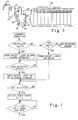
- Figure 1 is a pictorial block schematic of an automatic watering system of the present invention showing the relative elevational disposition of the components;
- Figure 2 is a side view of the watering system illustrating a gassing condition of the battery;
- Figure 3 is a side view of the watering system illustrating cell watering;
- Figure 4 is a side view of the watering system illustrating watering flow-through of the cells;
- Figure 5 is a side view of the watering system illustrating syphon evacuation of the cell caps;
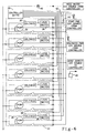
- Figure 6 is an electrical schematic of the watering system;
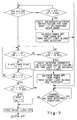
- Figures 7-9 are flow charts illustrating the operation of the watering system; and
- Figure 10 is a timing diagram of the watering system during and after cell watering.
- An embodiment of the invention is illustrated in Figure 1. Automatic
battery watering system 8 provides water on an 'as needed' basis tobattery 10.Battery 10 is arranged to include 7separate watering ramps 11. Eachwatering ramp 11 includes twomodules 12 connected in series. Eachmodule 12 contains a series of interconnectedcells 14. Eachcell 14 has an associatedwatering cap 16 that provides water to the cell and vents gas evolution from the cell. Eachwatering ramp 11 is associated with areservoir 18. The invention is primarily intended for use with high voltage and high powered batteries which are typically used in electric vehicle applications. To reduce the electrical hazards of watering this type of battery, the watering system is designed so that no portion ofwatering system 8 is exposed to the total battery voltage. -
Reservoir 18 is a generally vertical container receiving deionised water from wateringmanifold 20. Deioniser 22 receivestap water hose 24 and removes unwanted ions.Reservoir 18 is connected toramp 11 through fill/drain conduit 26 andoverflow conduit 28.Conduit 26 provides water tocell cap 16 and drains unused water within the cell caps and conduit toreservoir 18. Whencells 14 are fully watered, excess water flows throughcell caps 16 and returns toreservoir 18 throughconduit 28. After cell watering is completed, power topump 30 is removed and water withincell caps 16 and conduit 28 drains intoreservoir 18 by a gravity syphon throughconduit 26. -
Reversible pump 30 operates in a manner to pump water throughconduit 26 and cell caps 16 when power is applied to the pump motor (pump motor not separately shown). When power is removed from the pump, pump 30 permits the reverse flow of water into the reservoir.Pump 30 does not operate in a reverse mode.Pump 30 need only permit the reverse flow of water through the pump by syphon. Representative reversible pumps include centrifugal, propeller, or turbine type pumps. Sealing type pumps such as diaphragms, peristolic and piston pumps do not generally permit a reverse flow of water through the pump and are therefore not suitable for the present invention. -
Reservoir 18,conduit 28 and wateringcaps 16 are continuously vented throughcombustible vapour vent 32. Isolation of the ramps during venting limits the loss of modules to that ramp in the event of ignition.Reservoir 18 may be located immediately adjacent or attached tobattery 12 or at a location remote frombattery 12.Reservoir 18 is positioned below the height of cell caps 16 to drain water within cell caps 16 andconduits Reservoir 18,manifold 20 andconduits valve 38 operates to replenishreservoir 18 with deionised water. - Figures 2-5 generally illustrate the operation of the battery before, during and after cell watering. Figure 2 illustrates a gassing condition occurring during cell overcharge. Nickel based batteries generally require overcharge to bring the nickel electrode up to 100% of electron capacity. Overcharge of the battery occurs when energy applied to the battery during charging converts water in the electrolyte to gas through electrolysis. The negative electrode (cadmium or hydride) is generally fully charged before the positive electrode (nickel). The charging energy necessary to bring the nickel electrode to 100 percent of capacity is generally between 15 and 20 percent of the total energy used in recharging and results in gas generation.
Gas exit cells 14 through wateringcaps 16 and is vented throughconduit 28 andvent 32. After sufficient time passes so that the positive electrode is totally restored to 100 percent of capacity, the system initiates the watering process. - Figure 3 illustrates cell watering. At the completion of overcharge, power is applied to pump 30.
Pump 30 supplies water to wateringcaps 16 to fillcells 14. After eachindividual cell 14 is filled to capacity, the overflow travels throughconduit 28 intoreservoir 18. A period of overflow assures that each cell is completely replenished with water as shown in Figure 4. After the flow through period, power is removed frompump 30 as shown in Figure 5. Water withinconduits pump 30 and intoreservoir 18 by a gravity siphon.Pump 30 need not be hydraulically reversible, it need only permit the reverse flow of fluid through the pump.Float 34 senses the water level withinreservoir 18 and closesreed switch 36 when the water level drops below a predefined threshold.Switch 36 causessolenoid valve 38 to open and admit pressurised deionised water intoreservoir 18. As the water level inreservoir 18 rises, float 34 causes switch 36 to closevalve 38 afterreservoir 18 is filled sufficiently. Gas withinreservoir 18 is displaced by the replenishing water and is exhausted throughvent 32. - Electrical schematic of Figure 6 illustrates the circuitry used by
battery watering system 8. Controller 39 (CNTR) is a microprocessor that operates the various electrical components of wateringsystem 8.Controller 39 may be used solely for purposes of the watering system or alternatively it may be a general purpose microprocessor used in the operation of the vehicle or the vehicle charging system.Indicator light 40, mounted in the vicinity of the charger connection, signals that the battery cells need water.Relay contacts solenoid valves 38 respectively.Hose detection circuit 46 signals if wateringhose 24 is connected todeioniser 22. - The control parameters for watering
system 8 are illustrated in Figures 7-9. Beginning in Figure 7, an external electrical source attaches to the vehicle charger.Controller 39 senses the total amount of amp-hours passing throughbattery 10 during overcharge (Cah). If Cah is greater than constant C2, then the amount of overcharge that has occurred inbattery 10 has probably electrolysed sufficient water to require the replenishment of wateringsystem 8 from an external water source. If Cah is greater than C1, then cell watering may occur. Pressurised water is available toreservoir 18 and supplies water tocells 14.Controller 39 monitors Cah and causes light 40 to alert the operator to the need for water ("Need Water" light 40 on). If Cah is less than C1, the amount of overcharge has likely not caused a great deal of electrolyte electrolysis and therefore no watering need occur. When Cah is greater than C2, the charger is disabled unlesshose 24 is connected todeioniser 22. The battery is charged until an end of charge (EOC) is detected.Controller 39 then begins a first timer T1 which is a function of the evolution of gas from the recently overcharged battery and the cell cap configuration. Typical times are about 44 minutes. - Moving to Figure 8, power is supplied to the
solenoid valve 38/switch 36 couple. If the level offloat 34 senses thatreservoir 18 needs water, then switch 36causes valve 38 to open and admit water toreservoir 18. Afterreservoir 18 is filled, switch 36causes valve 38 to close. Each opening and closing appears as a voltage pulse.Controller 39 records these pulses in a memory. Ascells 14 fill with water, the water withinreservoir 18 causes float 34 to drop and to openvalve 38. The repeated opening and closing ofvalve 38 produces a cycling pattern as illustrated in Figure 10. Five on/off cycles are usually sufficient to assume the system is working properly. -
Controller 39 senses the solenoid voltage (SV) for each watering ramp i (Sense line). If any line i fails to record 5 pulses (SVs), thencontroller 39 records a failure event and displays a fault ("Need Water" light 40 blinks).Controller 39 can also monitor the pump power (Pump Pwr), solenoid power (Solenoid Pwr), hose detect or charger cord detect (Charger Cord Det) to precisely determine the location of various faults. While a single continuous or blinkinglight 40 has been used to display the condition of the watering system, other more detailed display means are also possible. - After the solenoids stop cycling on and off,
controller 39 senses thatcells 14 are completely filled. After a sufficient period of time has elapsed for flow through (usually 30 seconds),controller 39 removes power fromvalve 38/switch 36 and pump 30 and resets Cah to 0. Ifcontroller 39 has not record any component failures (the presence of 5 or more SVs for each watering ramp or other system fault), then light 40 is turned off. This signals the operator that the watering system has functioned properly and the cells are filled.
Claims (7)
- A battery watering system comprising:
a battery (10) having a plurality of cells (14) connected in series;
a watering cap (16) associated with each said cell (14);
a reservoir (18) communicating water from said watering caps (16) through a first watering conduit (28); and
a reversible pump (30) communicating water from said reservoir (16) to a second watering conduit (26), and said second watering conduit (26) communicating water to said watering caps (16), said pump (30) being positioned below said watering caps (16) whereby water within said watering caps (16) and said second watering conduit (26) drains through said pump (30) by siphon. - A battery watering system as claimed in claim 1 and further comprising a controller sensing the need for cell watering and operating said pump to provide water to said cell.
- A battery watering system as claimed in claim 2 and further comprising a water level sensor sensing the water level within said reservoir and causing a valve to admit water into said reservoir when the water within said reservoir is low.
- A battery watering system as claimed in claim 3, wherein said controller records the operation of said valve and signals an operator in the event said battery watering system fails.
- A battery watering system as claimed in claim 1, wherein said battery comprises a plurality of watering ramps, each said watering ramp supplies water to one or more modules, said module comprising a plurality of said cells; each said watering ramp being associated with one said reservoir, each said watering ramp being electrically isolated from the other said watering ramps.
- A battery watering system comprising:
a battery having a plurality of modules connected in series, each said module having a plurality of cells connected in series;
a watering cap associated with each said cell;
one or more watering ramps providing water to said modules;
a reservoir associated with each said watering ramp communicating water from said watering caps through a first watering conduit;
a valve associated with each said watering ramp operable to admit deionised water into said reservoir;
a water level sensor sensing the water level within each said reservoir and causing said valve to open and admit water into said reservoir when the water within said reservoir is low;
a reversible pump associated with each said watering ramp communicating water from said reservoir to a second watering conduit, said second watering conduit communicating water to said watering caps of said module, said pump being positioned below said watering caps whereby water within said watering caps and said second watering conduit drains through said pump by siphon; and
a controller sensing the need for cell watering and operating said pump to provide water to said cells, said controller recording the operation of said valve to determine the normal operation of said watering system and signalling an operator of successful and unsuccessful battery watering. - A method of watering a battery comprising the steps of:
charging said battery and recording the amp hours of overcharge;
signally a "need water" alert to an operator if said overcharge amp hours exceeds an amount;
sensing the connection of a pressurised water source to a water inlet and preventing battery charging in the event said connection is absent;
operating a pump to provide water to said cells;
operating a valve to admit water into a reservoir and recording the operation of said valve;
signalling a "failure" alert to said operator if said valve or pump fail to operate properly; and
signalling a successful battery watering if said watering system operates properly.
Applications Claiming Priority (2)
| Application Number | Priority Date | Filing Date | Title |
|---|---|---|---|
| US369636 | 1995-01-06 | ||
| US08/369,636 US5453334A (en) | 1995-01-06 | 1995-01-06 | Automatic battery watering system |
Publications (2)
| Publication Number | Publication Date |
|---|---|
| EP0721228A1 true EP0721228A1 (en) | 1996-07-10 |
| EP0721228B1 EP0721228B1 (en) | 1999-10-06 |
Family
ID=23456266
Family Applications (1)
| Application Number | Title | Priority Date | Filing Date |
|---|---|---|---|
| EP95309374A Expired - Lifetime EP0721228B1 (en) | 1995-01-06 | 1995-12-21 | Automatic battery watering system |
Country Status (3)
| Country | Link |
|---|---|
| US (1) | US5453334A (en) |
| EP (1) | EP0721228B1 (en) |
| DE (1) | DE69512628T2 (en) |
Cited By (2)
| Publication number | Priority date | Publication date | Assignee | Title |
|---|---|---|---|---|
| US7040431B2 (en) | 2003-08-18 | 2006-05-09 | Daimlerchrysler Corporation | Fuel cell hybrid vehicle with automatically watered aqueous batteries |
| EP2395577A3 (en) * | 2010-06-10 | 2012-02-01 | Hagemann-Systems GmbH | Method and system for supplying a container with different fluids |
Families Citing this family (31)
| Publication number | Priority date | Publication date | Assignee | Title |
|---|---|---|---|---|
| KR0139244B1 (en) * | 1995-06-02 | 1998-06-15 | 신재인 | Battery electrolyte height detection method and battery distilled water injection method and device |
| US5862830A (en) * | 1995-07-25 | 1999-01-26 | Landau Systemtechnik Gmbh | Water replenishing plug for a battery containing a liquid electrolyte |
| US6106968A (en) * | 1998-03-06 | 2000-08-22 | Lucent Technologies Inc. | Smart valve regulated lead acid battery with embedded electronic monitoring and fluid fill system |
| US6209573B1 (en) | 1998-06-02 | 2001-04-03 | Chin Lye Chau | Wet battery and vehicle-based water management system |
| DE10036462A1 (en) | 1999-07-26 | 2001-05-17 | Johan Christiaan Fitter | Filling system for multiple containers has delivery unit and filling unit with number of outlets arranged so that liquid can flow into corresponding number of inflow openings in containers |
| DE29915950U1 (en) * | 1999-09-10 | 1999-12-30 | CMW Automation GmbH, 65594 Runkel | Device for filling the cells of an accumulator with electrolyte |
| US6718996B2 (en) * | 2000-04-10 | 2004-04-13 | Club Car, Inc. | Filling pod for a battery, vehicle and method of supplying fluid to a battery |
| US6786226B2 (en) * | 2000-04-10 | 2004-09-07 | Club Car, Inc. | Battery fluid supply system |
| US6622744B2 (en) * | 2000-04-10 | 2003-09-23 | Club Car, Inc. | Filling pod for a battery, vehicle and method of supplying fluid to a battery |
| US6213145B1 (en) * | 2000-04-10 | 2001-04-10 | Club Car, Inc. | Battery water supply system for a battery-powered utility vehicle |
| US6338368B1 (en) | 2001-01-22 | 2002-01-15 | Donald S. Hassell | Electric golf car battery refill system |
| DE60318473T2 (en) * | 2002-10-25 | 2008-12-24 | Jones, William E.M. | ELECTRIC BATTERY WITH AUTONOMOUS REFILLING AND ACID MIXING SYSTEMS |
| WO2005109547A1 (en) * | 2004-05-09 | 2005-11-17 | Yun Li | Battery watering device |
| US20060089844A1 (en) * | 2004-10-26 | 2006-04-27 | Aerovironment, Inc., A California Corporation | Dynamic replenisher management |
| US7444192B2 (en) * | 2004-10-26 | 2008-10-28 | Aerovironment, Inc. | Reactive replenishable device management |
| US20090286142A9 (en) * | 2005-02-04 | 2009-11-19 | Flow-Rite Controls, Ltd. | Single point battery watering system including battery refill valves incorporating flame arrestors |
| WO2006130614A2 (en) | 2005-05-28 | 2006-12-07 | Aerovironment Inc. | Battery electrolyte level control system |
| FR2901642B1 (en) * | 2006-05-23 | 2012-11-16 | Enersys Europ Holding Co | APPARATUS FOR RECHARGING AND FILLING BATTERIES |
| DE102006054656A1 (en) * | 2006-06-09 | 2007-12-13 | Frötek - Vermögensverwaltung GmbH | Device for closing and / or filling a single galvanic cell, arrangement of a plurality of such closing devices, battery and / or accumulator for providing energy and method for determining a state of a battery and method for producing such a device |
| US20090004511A1 (en) * | 2007-06-26 | 2009-01-01 | Hlavac Mark J | Battery Watering System |
| US20110236730A1 (en) * | 2010-03-23 | 2011-09-29 | Jones William E M | Battery watering system |
| TWI508354B (en) * | 2012-04-04 | 2015-11-11 | Nissan Motor | Air battery |
| BR112015018963A2 (en) | 2013-02-11 | 2017-07-18 | Fluidic Inc | electrochemical cell recycling / recapture system |
| CN104966859B (en) * | 2015-07-14 | 2017-06-13 | 合肥献芝新能源有限公司 | It is a kind of can dormancy storage and in real time triggering power-supply system |
| US10115288B2 (en) | 2016-04-15 | 2018-10-30 | Ingersoll-Rand Company | Automatic battery fluid reminder system for vehicles with flooded lead acid batteries and method thereof |
| JP2019521497A (en) | 2016-07-22 | 2019-07-25 | ナントエナジー,インク. | Water and carbon dioxide management system in the electrochemical cell |
| US11228066B2 (en) | 2016-07-22 | 2022-01-18 | Form Energy, Inc. | Mist elimination system for electrochemical cells |
| CN119481486A (en) | 2018-06-29 | 2025-02-18 | 福恩能源公司 | Rolling diaphragm seal |
| CN112805868A (en) | 2018-06-29 | 2021-05-14 | 福恩能源公司 | Metal air electrochemical cell frame |
| CN114207915A (en) | 2019-06-28 | 2022-03-18 | 福恩能源公司 | Device architecture for metal-air battery |
| WO2021226399A1 (en) | 2020-05-06 | 2021-11-11 | Form Energy, Inc. | Decoupled electrode electrochemical energy storage system |
Citations (2)
| Publication number | Priority date | Publication date | Assignee | Title |
|---|---|---|---|---|
| EP0009990A2 (en) * | 1978-10-09 | 1980-04-16 | Chloride Group Public Limited Company | Battery filler and method of filling a battery using said filler |
| JPS55163767A (en) * | 1979-06-07 | 1980-12-20 | Yuasa Battery Co Ltd | Storage battery with water supplier |
Family Cites Families (10)
| Publication number | Priority date | Publication date | Assignee | Title |
|---|---|---|---|---|
| US2141079A (en) * | 1937-04-01 | 1938-12-20 | Charles M Bolich | Storage battery filling device |
| US3189063A (en) * | 1962-08-07 | 1965-06-15 | Lowe Charles Thomas | Battery watering device |
| JPS4981839A (en) * | 1972-12-14 | 1974-08-07 | ||
| US4353968A (en) * | 1981-07-15 | 1982-10-12 | Boyle Robert E | Battery water-filling systems and check valves therefor |
| US4399200A (en) * | 1981-11-05 | 1983-08-16 | Energy Development Associates, Inc. | Device for controlling a pump in a storage battery |
| US4522896A (en) * | 1983-03-23 | 1985-06-11 | Anglo-American Research Ltd. | Automatic watering system for batteries and fuel cells |
| SE448650B (en) * | 1985-08-14 | 1987-03-09 | Sab Nife Ab | WATER REFILLING VALVE FOR ELECTROCHEMICAL ACCUMULATOR BATTERIES |
| IT1204262B (en) * | 1986-01-29 | 1989-03-01 | Olimpio Stocchiero | CAP FOR ACCUMULATOR ELEMENTS WITH AUTOMATIC FILLING DEVICE |
| US5135820A (en) * | 1991-02-14 | 1992-08-04 | Jones William E M | Apparatus for recirculation of battery electrolyte and method of using same |
| US5284176A (en) * | 1992-06-30 | 1994-02-08 | Flow-Rite Controls, Ltd. | Battery refill system |
-
1995
- 1995-01-06 US US08/369,636 patent/US5453334A/en not_active Expired - Fee Related
- 1995-12-21 EP EP95309374A patent/EP0721228B1/en not_active Expired - Lifetime
- 1995-12-21 DE DE69512628T patent/DE69512628T2/en not_active Expired - Fee Related
Patent Citations (2)
| Publication number | Priority date | Publication date | Assignee | Title |
|---|---|---|---|---|
| EP0009990A2 (en) * | 1978-10-09 | 1980-04-16 | Chloride Group Public Limited Company | Battery filler and method of filling a battery using said filler |
| JPS55163767A (en) * | 1979-06-07 | 1980-12-20 | Yuasa Battery Co Ltd | Storage battery with water supplier |
Non-Patent Citations (1)
| Title |
|---|
| PATENT ABSTRACTS OF JAPAN vol. 005, no. 040 (E - 049) 17 March 1981 (1981-03-17) * |
Cited By (2)
| Publication number | Priority date | Publication date | Assignee | Title |
|---|---|---|---|---|
| US7040431B2 (en) | 2003-08-18 | 2006-05-09 | Daimlerchrysler Corporation | Fuel cell hybrid vehicle with automatically watered aqueous batteries |
| EP2395577A3 (en) * | 2010-06-10 | 2012-02-01 | Hagemann-Systems GmbH | Method and system for supplying a container with different fluids |
Also Published As
| Publication number | Publication date |
|---|---|
| EP0721228B1 (en) | 1999-10-06 |
| DE69512628T2 (en) | 2000-02-24 |
| US5453334A (en) | 1995-09-26 |
| DE69512628D1 (en) | 1999-11-11 |
Similar Documents
| Publication | Publication Date | Title |
|---|---|---|
| EP0721228B1 (en) | Automatic battery watering system | |
| EP0746046B1 (en) | Electrolyte level sensing and automatic topping up apparatus for storage wet cell | |
| CA1228892A (en) | Comb-type bipolar stack | |
| US6786226B2 (en) | Battery fluid supply system | |
| CN101223655A (en) | Flowing electrolyte battery with potential neutralization | |
| CN114268079B (en) | Intelligent battery power-exchanging cabinet system and control method | |
| CA1128988A (en) | Method and apparatus for storage battery electrolyte circulation | |
| US6213145B1 (en) | Battery water supply system for a battery-powered utility vehicle | |
| US8546006B2 (en) | System and method for delivering fluid to a battery | |
| EP1556913B1 (en) | Electric battery having autonomous watering and acid mixing systems | |
| CA1129049A (en) | Automatic water refilling of storage batteries | |
| KR20040055061A (en) | Automatic Power Supply Device of an Unmanned Observatory | |
| US6622744B2 (en) | Filling pod for a battery, vehicle and method of supplying fluid to a battery | |
| US6718996B2 (en) | Filling pod for a battery, vehicle and method of supplying fluid to a battery | |
| US20060105230A1 (en) | Automated battery watering control system | |
| US3434887A (en) | Battery fill apparatus | |
| US4288501A (en) | Reusable reserve battery system | |
| US5340667A (en) | Battery recirculation and recharge system | |
| US7104272B2 (en) | Vehicle battery fluid supply system with vacuum source | |
| US4517261A (en) | Hydrogen gas relief valve | |
| WO2020180953A1 (en) | Liquid sensing valve for a fire sprinkler system | |
| WO2022016701A1 (en) | Automatic water replenishing system for traction lead-acid storage battery | |
| EP3014687B1 (en) | Flow battery | |
| CN100483796C (en) | Cover for a battery and associated battery | |
| JPS5854551A (en) | Water supplying system for storage battery |
Legal Events
| Date | Code | Title | Description |
|---|---|---|---|
| PUAI | Public reference made under article 153(3) epc to a published international application that has entered the european phase |
Free format text: ORIGINAL CODE: 0009012 |
|
| AK | Designated contracting states |
Kind code of ref document: A1 Designated state(s): DE FR GB |
|
| 17P | Request for examination filed |
Effective date: 19961111 |
|
| 17Q | First examination report despatched |
Effective date: 19970416 |
|
| GRAG | Despatch of communication of intention to grant |
Free format text: ORIGINAL CODE: EPIDOS AGRA |
|
| GRAG | Despatch of communication of intention to grant |
Free format text: ORIGINAL CODE: EPIDOS AGRA |
|
| GRAG | Despatch of communication of intention to grant |
Free format text: ORIGINAL CODE: EPIDOS AGRA |
|
| GRAH | Despatch of communication of intention to grant a patent |
Free format text: ORIGINAL CODE: EPIDOS IGRA |
|
| GRAH | Despatch of communication of intention to grant a patent |
Free format text: ORIGINAL CODE: EPIDOS IGRA |
|
| GRAA | (expected) grant |
Free format text: ORIGINAL CODE: 0009210 |
|
| AK | Designated contracting states |
Kind code of ref document: B1 Designated state(s): DE FR GB |
|
| REF | Corresponds to: |
Ref document number: 69512628 Country of ref document: DE Date of ref document: 19991111 |
|
| ET | Fr: translation filed | ||
| REG | Reference to a national code |
Ref country code: FR Ref legal event code: TP Ref country code: FR Ref legal event code: CD |
|
| PLBE | No opposition filed within time limit |
Free format text: ORIGINAL CODE: 0009261 |
|
| STAA | Information on the status of an ep patent application or granted ep patent |
Free format text: STATUS: NO OPPOSITION FILED WITHIN TIME LIMIT |
|
| 26N | No opposition filed | ||
| PGFP | Annual fee paid to national office [announced via postgrant information from national office to epo] |
Ref country code: GB Payment date: 20001207 Year of fee payment: 6 |
|
| PGFP | Annual fee paid to national office [announced via postgrant information from national office to epo] |
Ref country code: DE Payment date: 20001213 Year of fee payment: 6 |
|
| PGFP | Annual fee paid to national office [announced via postgrant information from national office to epo] |
Ref country code: FR Payment date: 20001215 Year of fee payment: 6 |
|
| PG25 | Lapsed in a contracting state [announced via postgrant information from national office to epo] |
Ref country code: GB Free format text: LAPSE BECAUSE OF NON-PAYMENT OF DUE FEES Effective date: 20011221 |
|
| REG | Reference to a national code |
Ref country code: GB Ref legal event code: IF02 |
|
| PG25 | Lapsed in a contracting state [announced via postgrant information from national office to epo] |
Ref country code: DE Free format text: LAPSE BECAUSE OF NON-PAYMENT OF DUE FEES Effective date: 20020702 |
|
| GBPC | Gb: european patent ceased through non-payment of renewal fee |
Effective date: 20011221 |
|
| PG25 | Lapsed in a contracting state [announced via postgrant information from national office to epo] |
Ref country code: FR Free format text: LAPSE BECAUSE OF NON-PAYMENT OF DUE FEES Effective date: 20020830 |
|
| REG | Reference to a national code |
Ref country code: FR Ref legal event code: ST |