EP0720963A1 - Winding machine stopping method - Google Patents
Winding machine stopping method Download PDFInfo
- Publication number
- EP0720963A1 EP0720963A1 EP95922729A EP95922729A EP0720963A1 EP 0720963 A1 EP0720963 A1 EP 0720963A1 EP 95922729 A EP95922729 A EP 95922729A EP 95922729 A EP95922729 A EP 95922729A EP 0720963 A1 EP0720963 A1 EP 0720963A1
- Authority
- EP
- European Patent Office
- Prior art keywords
- speed
- motor
- command
- brake
- electromagnetic brake
- Prior art date
- Legal status (The legal status is an assumption and is not a legal conclusion. Google has not performed a legal analysis and makes no representation as to the accuracy of the status listed.)
- Granted
Links
Images


Classifications
-
- B—PERFORMING OPERATIONS; TRANSPORTING
- B66—HOISTING; LIFTING; HAULING
- B66C—CRANES; LOAD-ENGAGING ELEMENTS OR DEVICES FOR CRANES, CAPSTANS, WINCHES, OR TACKLES
- B66C13/00—Other constructional features or details
- B66C13/18—Control systems or devices
- B66C13/22—Control systems or devices for electric drives
- B66C13/23—Circuits for controlling the lowering of the load
-
- B—PERFORMING OPERATIONS; TRANSPORTING
- B66—HOISTING; LIFTING; HAULING
- B66D—CAPSTANS; WINCHES; TACKLES, e.g. PULLEY BLOCKS; HOISTS
- B66D1/00—Rope, cable, or chain winding mechanisms; Capstans
- B66D1/28—Other constructional details
- B66D1/40—Control devices
- B66D1/42—Control devices non-automatic
- B66D1/46—Control devices non-automatic electric
-
- B—PERFORMING OPERATIONS; TRANSPORTING
- B66—HOISTING; LIFTING; HAULING
- B66D—CAPSTANS; WINCHES; TACKLES, e.g. PULLEY BLOCKS; HOISTS
- B66D5/00—Braking or detent devices characterised by application to lifting or hoisting gear, e.g. for controlling the lowering of loads
- B66D5/02—Crane, lift hoist, or winch brakes operating on drums, barrels, or ropes
- B66D5/24—Operating devices
- B66D5/30—Operating devices electrical
Definitions
- the present invention relates to a method of stopping a winding machine which is used for winching a crane rope up and down.
- Winding machines of this type which use electric motors for driving and electromagnetic brakes for stopping, are compelled to manage the critical timing of the operation of the motor and electromagnetic brake during the transition from working to stopping. For example, when an operator wishes to winch down a load with a crane rope and stop the crane when the load reaches a certain height, if the activation of the electromagnetic brake comes after the motor stops, the crane rope will temporarily be in a no-torque state, resulting in the dangerous descent of the load.
- Fig. 1 is a block diagram of the control circuit of this prior art
- Fig.2 is the timing chart at stopping.
- a winch induction motor M 1 has its output shaft coupled at one end to the drum of an electromagnetic brake MB and at another end to the winch drum D through a reduction gear G.
- a variable-voltage, variable-frequency inverter I 1 Connected between the primary winder of the induction motor M 1 and the power source is a variable-voltage, variable-frequency inverter I 1 , which is also connected to the electromagnetic brake MB by way of a brake controller BC.
- the electromagnetic brake is activated during the rotation of the motor, and therefore has the problem of prematurely wearing the electromagnetic brake.
- Another problem is that the control ceases at time t 9 when the speed command N REF reaches zero, causing the current command to become zero, even if the electromagnetic brake is not activated, in which case the descent of the load will occur.
- an object of the present invention is to prevent abrasion of the electromagnetic brake and the descent of the load.
- the inventive method of stopping of a winding machine which operates to winch a load up or down in response to a torque command to an electric motor produced by a speed controller in accordance with a speed command generated by a speed command generation circuit, is designed to stop the motor control at the cessation of the machine if the motor speed is zero after the torque command for the motor is brought to zero for a predetermined length of time following the issuance of a brake command to the electromagnetic brake which is coupled directly to the motor.
- the motor does not rotate when the torque command is reduced to zero for a predetermined length of time following the activation of the electromagnetic brake after the motor has stopped completely based on the operation of the above-mentioned means, it can be judged that the electromagnetic brake is producing a torque sufficient to withstand the load at that time, and therefore the descent of load can be prevented even in the absence of the motor control.
- the brake will incur abrasion.
- the present invention resides in the winding control for winching a load up or down based on the issuance of a torque command to the motor produced by a speed controller in accordance with a speed command generated by a speed command generation circuit, wherein the motor control ceases at the stopping of the machine if the motor speed is zero after the torque command to the motor is brought to zero for a predetermined length of time following the issuance of a brake command to the electromagnetic brake which is coupled directly to the motor, whereby the abrasion of brake and the descent of load can be prevent.
- Fig. 1 is a schematic diagram showing the arrangement of a conventional winding machine
- Fig. 2 is a timing chart used to explain the operation at the stopping of the winding machine
- Fig. 3 is a block diagram showing the principal arrangement of an embodiment of this invention of a method of stopping of a winding machine
- Fig. 4 is a timing chart used to explain the operation of this embodiment
- Fig.5 is a flowchart of the control sequence for the brake command generation circuit based on this invention.
- reference symbol M denotes an induction motor.
- the difference in the speed N FB of the induction motor M detected by a speed detector PG, such as a pulse tachogenerator, from the speed command N REF produced by a speed command generation circuit NRC is fed to a speed controller ASR.
- a following torque command limit circuit TLIM which limits the torque command value produces a torque command T REF , which is fed to a vector-control inverter INV, by which the induction motor M is driven.
- the stop command SR and the motor speed N FB detected by the speed detector PG are fed to a brake command generation circuit BRC, which issues a brake command BR to an electromagnetic brake B.
- the speed command generation circuit NRC produces a decreasing speed command N REF , and the motor speed N FB falls accordingly.
- the brake command generation circuit BRC issues a brake command BR to the electromagnetic brake B at time t 3 , and it operates accordingly. Since the electromagnetic brake B operates in the state of zero motor speed N FB , it does not suffer any abrasion.
- the time period from t 3 to t 4 is to allow for the delay in operation of the electromagnetic brake B.
- Torque command limit circuit TLIM reduces the torque command T REF to zero within the time period from t 4 to t 5 . After time t 4 , if the motor speed N FB remains at zero at a zero torque command, indicative of the generation by the electromagnetic brake B of a braking torque which withstands the load, the descent of the load will not occur even though the control of the induction motor has ceased. Accordingly, the control of the induction motor can be stopped at time t 6 .
- Fig. 5 shows the control sequence of braking implemented by the brake command generation circuit BRC.
- the circuit BRC receives a stop command SR (step 100)
- it monitors the motor speed N FB (step 110), and it operates a timer to measure the time after the motor speed N FB has reached zero (step 120).
- the brake command generation circuit BRC issues a brake command BR to the electromagnetic brake B to thereby activate it (step 140).
- the present invention can be applied to the field of winding machines used for overhead traveling cranes in various plants and storage yards.
Abstract
Description
- The present invention relates to a method of stopping a winding machine which is used for winching a crane rope up and down.
- Winding machines of this type, which use electric motors for driving and electromagnetic brakes for stopping, are compelled to manage the critical timing of the operation of the motor and electromagnetic brake during the transition from working to stopping. For example, when an operator wishes to winch down a load with a crane rope and stop the crane when the load reaches a certain height, if the activation of the electromagnetic brake comes after the motor stops, the crane rope will temporarily be in a no-torque state, resulting in the dangerous descent of the load.
- To deal with this matter, Unexamined Japanese Patent publication No. Sho 59-124690 discloses a method of controlling the timing of the operation of the motor and electromagnetic brake in which the electromagnetic brake is activated immediately before the motor stops, thereby halting the descent of load. Fig. 1 is a block diagram of the control circuit of this prior art, and Fig.2 is the timing chart at stopping.
- In the figure, a winch induction motor M1 has its output shaft coupled at one end to the drum of an electromagnetic brake MB and at another end to the winch drum D through a reduction gear G. Connected between the primary winder of the induction motor M1 and the power source is a variable-voltage, variable-frequency inverter I1, which is also connected to the electromagnetic brake MB by way of a brake controller BC.
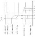
- The operation of the system will be explained with reference to Fig. 2. When a stop command SR is issued to the inverter I1 at time t7, the speed command NREF to the induction motor M1 decreases, and the motor speed NFB falls accordingly. When the motor speed NFB has fallen to a prescribed level (immediately before the stop), a brake command BR is issued to the electromagnetic brake MB at time t8 thereby to activate it.
- In the above prior art method of stopping of a winding machine, the electromagnetic brake is activated during the rotation of the motor, and therefore has the problem of prematurely wearing the electromagnetic brake. Another problem is that the control ceases at time t9 when the speed command NREF reaches zero, causing the current command to become zero, even if the electromagnetic brake is not activated, in which case the descent of the load will occur.
- Accordingly, an object of the present invention is to prevent abrasion of the electromagnetic brake and the descent of the load.
- In order to achieve the above objective, the inventive method of stopping of a winding machine, which operates to winch a load up or down in response to a torque command to an electric motor produced by a speed controller in accordance with a speed command generated by a speed command generation circuit, is designed to stop the motor control at the cessation of the machine if the motor speed is zero after the torque command for the motor is brought to zero for a predetermined length of time following the issuance of a brake command to the electromagnetic brake which is coupled directly to the motor.
- In the inventive method of stopping of a winding machine, if the motor does not rotate when the torque command is reduced to zero for a predetermined length of time following the activation of the electromagnetic brake after the motor has stopped completely based on the operation of the above-mentioned means, it can be judged that the electromagnetic brake is producing a torque sufficient to withstand the load at that time, and therefore the descent of load can be prevented even in the absence of the motor control. By activating the electromagnetic brake during the stoppage of the motor, the brake will incur abrasion.
- The present invention resides in the winding control for winching a load up or down based on the issuance of a torque command to the motor produced by a speed controller in accordance with a speed command generated by a speed command generation circuit, wherein the motor control ceases at the stopping of the machine if the motor speed is zero after the torque command to the motor is brought to zero for a predetermined length of time following the issuance of a brake command to the electromagnetic brake which is coupled directly to the motor, whereby the abrasion of brake and the descent of load can be prevent.
- Fig. 1 is a schematic diagram showing the arrangement of a conventional winding machine; Fig. 2 is a timing chart used to explain the operation at the stopping of the winding machine; Fig. 3 is a block diagram showing the principal arrangement of an embodiment of this invention of a method of stopping of a winding machine; Fig. 4 is a timing chart used to explain the operation of this embodiment; and Fig.5 is a flowchart of the control sequence for the brake command generation circuit based on this invention.
- An embodiment of this invention will be explained with reference to the drawings.
- In Fig. 3, reference symbol M denotes an induction motor. The difference in the speed NFB of the induction motor M detected by a speed detector PG, such as a pulse tachogenerator, from the speed command NREF produced by a speed command generation circuit NRC is fed to a speed controller ASR. A following torque command limit circuit TLIM which limits the torque command value produces a torque command TREF, which is fed to a vector-control inverter INV, by which the induction motor M is driven. The stop command SR and the motor speed NFB detected by the speed detector PG are fed to a brake command generation circuit BRC, which issues a brake command BR to an electromagnetic brake B.
- The operation of the circuit shown in Fig. 3 will be explained in connection with the timing chart of Fig. 4.
- During the operation of the induction motor M, when a stop command SR shown in Fig. 3 is issued at time t1 (
step 100 in Fig. 5), the speed command generation circuit NRC produces a decreasing speed command NREF, and the motor speed NFB falls accordingly. After the motor speed NFB has reached zero at time t2, the brake command generation circuit BRC issues a brake command BR to the electromagnetic brake B at time t3, and it operates accordingly. Since the electromagnetic brake B operates in the state of zero motor speed NFB, it does not suffer any abrasion. The time period from t3 to t4 is to allow for the delay in operation of the electromagnetic brake B. Torque command limit circuit TLIM reduces the torque command TREF to zero within the time period from t4 to t5. After time t4, if the motor speed NFB remains at zero at a zero torque command, indicative of the generation by the electromagnetic brake B of a braking torque which withstands the load, the descent of the load will not occur even though the control of the induction motor has ceased. Accordingly, the control of the induction motor can be stopped at time t6. - Fig. 5 shows the control sequence of braking implemented by the brake command generation circuit BRC. In the figure, when the circuit BRC receives a stop command SR (step 100), it monitors the motor speed NFB (step 110), and it operates a timer to measure the time after the motor speed NFB has reached zero (step 120). When the timer value has fallen below the value of t3-t2 (step 130), the brake command generation circuit BRC issues a brake command BR to the electromagnetic brake B to thereby activate it (step 140).
- The present invention can be applied to the field of winding machines used for overhead traveling cranes in various plants and storage yards.
Claims (2)
- A method of stopping of a winding machine which operates to winch a load up or down in response to a torque command to an electric motor produced by a speed controller in accordance the a speed command generated by a speed command generation circuit, wherein at the stopping of the machine the motor control is ceased if the motor speed NFB is zero after the torque command to said motor is brought to zero for a predetermined length of time following the issuance of a brake command to an electromagnetic brake which is coupled directly to said motor.
- A method of stopping of a winding machine according to claim 1, wherein a timer is operated to keep track of the time after the motor speed has reached zero, and a brake command is issued by a brake command generation circuit to said electromagnetic brake when the timer value has fallen below a prescribed value thereby to activate said electromagnetic brake.
Applications Claiming Priority (4)
| Application Number | Priority Date | Filing Date | Title |
|---|---|---|---|
| JP14053194 | 1994-06-22 | ||
| JP140531/94 | 1994-06-22 | ||
| JP14053194A JP3834073B2 (en) | 1994-06-22 | 1994-06-22 | How to stop the hoisting / unwinding machine |
| PCT/JP1995/001238 WO1995035254A1 (en) | 1994-06-22 | 1995-06-21 | Winding machine stopping method |
Publications (3)
| Publication Number | Publication Date |
|---|---|
| EP0720963A1 true EP0720963A1 (en) | 1996-07-10 |
| EP0720963A4 EP0720963A4 (en) | 1996-11-20 |
| EP0720963B1 EP0720963B1 (en) | 1999-08-25 |
Family
ID=15270840
Family Applications (1)
| Application Number | Title | Priority Date | Filing Date |
|---|---|---|---|
| EP95922729A Expired - Lifetime EP0720963B1 (en) | 1994-06-22 | 1995-06-21 | Winding machine stopping method |
Country Status (7)
| Country | Link |
|---|---|
| US (2) | USRE37976E1 (en) |
| EP (1) | EP0720963B1 (en) |
| JP (1) | JP3834073B2 (en) |
| CN (1) | CN1037257C (en) |
| DE (1) | DE69511674T2 (en) |
| FI (1) | FI111625B (en) |
| WO (1) | WO1995035254A1 (en) |
Families Citing this family (21)
| Publication number | Priority date | Publication date | Assignee | Title |
|---|---|---|---|---|
| JP2001346400A (en) * | 2000-06-01 | 2001-12-14 | Matsushita Electric Ind Co Ltd | Motor brake releasing device |
| DE10203375A1 (en) * | 2002-01-29 | 2003-08-14 | Siemens Ag | Method for holding a machine element and / or a load connected to it |
| US7004456B2 (en) * | 2002-10-03 | 2006-02-28 | Key Energy Services, Inc. | Engine speed limiter for a hoist |
| US7190146B1 (en) * | 2003-08-18 | 2007-03-13 | Magnetek, Inc. | Control system and method for an overhead bridge crane |
| US7063306B2 (en) * | 2003-10-01 | 2006-06-20 | Paccar Inc | Electronic winch monitoring system |
| GB0617980D0 (en) * | 2006-09-08 | 2006-10-18 | Siemens Plc | Motor electromagnetic brake control with fast current decay |
| JP5159593B2 (en) * | 2008-12-24 | 2013-03-06 | 日本車輌製造株式会社 | Pile driver |
| US9099148B2 (en) * | 2012-03-30 | 2015-08-04 | Oracle International Corporation | Magnetic Z-directional clutch |
| CN102677631A (en) * | 2012-05-02 | 2012-09-19 | 广东省源天工程公司 | Concrete vibrating equipment and side slope concrete construction method |
| CN102730567B (en) * | 2012-07-09 | 2014-04-16 | 中联重科股份有限公司 | Lifting control equipment, method, system and crane |
| WO2014112044A1 (en) * | 2013-01-16 | 2014-07-24 | 三井造船株式会社 | Method for controlling port loading and unloading equipment to reduce loading and unloading time, and port loading and unloading equipment |
| CN103332622B (en) * | 2013-07-02 | 2016-07-13 | 中科华核电技术研究院有限公司 | Nuclear fuel assembly transhipment electric block |
| CN103496651A (en) * | 2013-10-17 | 2014-01-08 | 昆明泰德威机电设备有限公司 | Method and device for determining gate-closing zero-point position in the process of descent of gate winch |
| CN104192750B (en) * | 2014-08-27 | 2016-07-06 | 安徽广德昌立制动器有限公司 | Universal elevator brake voltage regulator control circuit |
| DE102015218300B4 (en) | 2015-09-23 | 2019-10-31 | Flender Gmbh | Motor-driven crane drive, method of operation, and control unit |
| US10144623B2 (en) * | 2016-07-21 | 2018-12-04 | Ace World Companies, Ltd. | Brake failure in variable frequency drive motors |
| JP2018110474A (en) * | 2016-12-28 | 2018-07-12 | マブチモーター株式会社 | Control unit and control method of the same |
| US10501293B2 (en) | 2017-01-31 | 2019-12-10 | Goodrich Aerospace Services Private Limited | Method of applying brake to a hoist by electromagnetic means in a permanent magnet motor |
| CN108975192B (en) * | 2018-09-28 | 2020-07-17 | 中国人民解放军火箭军工程大学 | Double-brake electric hoist fault emergency load safety release system and method |
| US11199049B2 (en) * | 2019-02-14 | 2021-12-14 | Tie Down, Inc. | Winch utility |
| WO2022159640A1 (en) * | 2021-01-20 | 2022-07-28 | Allied Motion Technologies Inc. | Systems and methods for power management for a winch |
Citations (6)
| Publication number | Priority date | Publication date | Assignee | Title |
|---|---|---|---|---|
| US4083431A (en) * | 1975-05-09 | 1978-04-11 | Hitachi, Ltd. | Elevator control apparatus |
| US4090117A (en) * | 1975-09-25 | 1978-05-16 | Hitachi, Ltd. | Magnetic disc apparatus |
| US4207508A (en) * | 1977-04-14 | 1980-06-10 | Habisohn Victor J | Variable speed motor control system |
| US4493398A (en) * | 1982-05-03 | 1985-01-15 | Iventio Ag | Drive control for a transportation system, especially an elevator |
| US5247140A (en) * | 1990-08-13 | 1993-09-21 | Otis Elevator Company | Brake control system in elevator control apparatus |
| US5343134A (en) * | 1993-05-03 | 1994-08-30 | Harnischfeger Corporation | Method for checking brake torque |
Family Cites Families (7)
| Publication number | Priority date | Publication date | Assignee | Title |
|---|---|---|---|---|
| US4087078A (en) * | 1976-04-14 | 1978-05-02 | Hitachi, Ltd. | Moving apparatus for a load |
| US4276498A (en) * | 1977-12-09 | 1981-06-30 | Brown & Root, Inc. | Adjustable torque control winch system |
| JPS5552894A (en) * | 1978-10-14 | 1980-04-17 | Mitsubishi Electric Corp | Hoist halt controller |
| JPS5593798A (en) * | 1979-01-08 | 1980-07-16 | Mitsubishi Electric Corp | Jack gear |
| JPS59124690A (en) * | 1982-12-27 | 1984-07-18 | 日立機電工業株式会社 | Method of controlling vertical motion of winding of movable travelling body |
| JPH0789750B2 (en) * | 1986-04-10 | 1995-09-27 | 株式会社安川電機 | Crane V / F inverter control method |
| CA2082966A1 (en) * | 1991-11-15 | 1993-05-16 | Donald John Holster | Winch assembly |
-
1994
- 1994-06-22 JP JP14053194A patent/JP3834073B2/en not_active Expired - Fee Related
-
1995
- 1995-06-21 DE DE69511674T patent/DE69511674T2/en not_active Expired - Fee Related
- 1995-06-21 CN CN95190566A patent/CN1037257C/en not_active Expired - Lifetime
- 1995-06-21 WO PCT/JP1995/001238 patent/WO1995035254A1/en active IP Right Grant
- 1995-06-21 US US09/454,171 patent/USRE37976E1/en not_active Expired - Lifetime
- 1995-06-21 US US08/596,261 patent/US5692733A/en not_active Ceased
- 1995-06-21 EP EP95922729A patent/EP0720963B1/en not_active Expired - Lifetime
-
1996
- 1996-02-21 FI FI960792A patent/FI111625B/en active
Patent Citations (6)
| Publication number | Priority date | Publication date | Assignee | Title |
|---|---|---|---|---|
| US4083431A (en) * | 1975-05-09 | 1978-04-11 | Hitachi, Ltd. | Elevator control apparatus |
| US4090117A (en) * | 1975-09-25 | 1978-05-16 | Hitachi, Ltd. | Magnetic disc apparatus |
| US4207508A (en) * | 1977-04-14 | 1980-06-10 | Habisohn Victor J | Variable speed motor control system |
| US4493398A (en) * | 1982-05-03 | 1985-01-15 | Iventio Ag | Drive control for a transportation system, especially an elevator |
| US5247140A (en) * | 1990-08-13 | 1993-09-21 | Otis Elevator Company | Brake control system in elevator control apparatus |
| US5343134A (en) * | 1993-05-03 | 1994-08-30 | Harnischfeger Corporation | Method for checking brake torque |
Non-Patent Citations (1)
| Title |
|---|
| See also references of WO9535254A1 * |
Also Published As
| Publication number | Publication date |
|---|---|
| CN1037257C (en) | 1998-02-04 |
| US5692733A (en) | 1997-12-02 |
| FI960792A0 (en) | 1996-02-21 |
| DE69511674T2 (en) | 1999-12-23 |
| FI960792A (en) | 1996-04-15 |
| JP3834073B2 (en) | 2006-10-18 |
| EP0720963A4 (en) | 1996-11-20 |
| CN1129931A (en) | 1996-08-28 |
| JPH082884A (en) | 1996-01-09 |
| USRE37976E1 (en) | 2003-02-04 |
| DE69511674D1 (en) | 1999-09-30 |
| WO1995035254A1 (en) | 1995-12-28 |
| FI111625B (en) | 2003-08-29 |
| EP0720963B1 (en) | 1999-08-25 |
Similar Documents
| Publication | Publication Date | Title |
|---|---|---|
| EP0720963B1 (en) | Winding machine stopping method | |
| EP1190980B1 (en) | Method for controlling crane brake operation | |
| CN109715547B (en) | Electric hoist device | |
| AU636244B2 (en) | Control system for a mine winder | |
| JPWO2008015749A1 (en) | Elevator equipment | |
| US4719995A (en) | Control apparatus for A.C. elevator | |
| JP3144640B2 (en) | Control method and device for hoisting motor | |
| JPH0111659Y2 (en) | ||
| JPH08208189A (en) | Method and equipment for supervision of electric driving device and/or control of revolving speed | |
| CA2074203C (en) | Method and apparatus for operating a hoist | |
| KR920004309B1 (en) | Control device for elevator | |
| JP2019011165A (en) | Hoist and hoist overload detection method | |
| JPS59124690A (en) | Method of controlling vertical motion of winding of movable travelling body | |
| JPH11180687A (en) | Control method for hoist crane device | |
| JP4732578B2 (en) | Elevator control device | |
| JP2003267639A (en) | Power supply unit of elevator car | |
| US4661757A (en) | Controller for AC elevator | |
| US5179336A (en) | Method for decreasing the speed of an alternating current motor | |
| JP4295408B2 (en) | Crane main winding drive control device and control method | |
| JP3147199B2 (en) | Variable speed hoist for hanging | |
| KR100295877B1 (en) | Speed controller of elevator | |
| JPS58202270A (en) | Controller for elevator | |
| JP2906892B2 (en) | Method for preventing heavy objects from falling in motor drive device capable of controlling torque | |
| JP2000103592A (en) | Control method for hoist crane device | |
| JPH0779583A (en) | Device for driving winch for coal mine |
Legal Events
| Date | Code | Title | Description |
|---|---|---|---|
| PUAI | Public reference made under article 153(3) epc to a published international application that has entered the european phase |
Free format text: ORIGINAL CODE: 0009012 |
|
| 17P | Request for examination filed |
Effective date: 19960502 |
|
| AK | Designated contracting states |
Kind code of ref document: A1 Designated state(s): DE GB IT |
|
| A4 | Supplementary search report drawn up and despatched | ||
| AK | Designated contracting states |
Kind code of ref document: A4 Designated state(s): DE GB IT |
|
| GRAG | Despatch of communication of intention to grant |
Free format text: ORIGINAL CODE: EPIDOS AGRA |
|
| 17Q | First examination report despatched |
Effective date: 19981007 |
|
| GRAG | Despatch of communication of intention to grant |
Free format text: ORIGINAL CODE: EPIDOS AGRA |
|
| GRAH | Despatch of communication of intention to grant a patent |
Free format text: ORIGINAL CODE: EPIDOS IGRA |
|
| GRAH | Despatch of communication of intention to grant a patent |
Free format text: ORIGINAL CODE: EPIDOS IGRA |
|
| GRAA | (expected) grant |
Free format text: ORIGINAL CODE: 0009210 |
|
| AK | Designated contracting states |
Kind code of ref document: B1 Designated state(s): DE GB IT |
|
| REF | Corresponds to: |
Ref document number: 69511674 Country of ref document: DE Date of ref document: 19990930 |
|
| ITF | It: translation for a ep patent filed |
Owner name: FUMERO BREVETTI S.N.C. |
|
| PLBI | Opposition filed |
Free format text: ORIGINAL CODE: 0009260 |
|
| PLBF | Reply of patent proprietor to notice(s) of opposition |
Free format text: ORIGINAL CODE: EPIDOS OBSO |
|
| 26 | Opposition filed |
Opponent name: SIEMENS AG ZENTRALABTEILUNG TECHNIK ABTLG. ZT PA 1 Effective date: 20000524 |
|
| PLBF | Reply of patent proprietor to notice(s) of opposition |
Free format text: ORIGINAL CODE: EPIDOS OBSO |
|
| REG | Reference to a national code |
Ref country code: GB Ref legal event code: IF02 |
|
| PLBO | Opposition rejected |
Free format text: ORIGINAL CODE: EPIDOS REJO |
|
| PLBN | Opposition rejected |
Free format text: ORIGINAL CODE: 0009273 |
|
| STAA | Information on the status of an ep patent application or granted ep patent |
Free format text: STATUS: OPPOSITION REJECTED |
|
| 27O | Opposition rejected |
Effective date: 20020304 |
|
| PLAB | Opposition data, opponent's data or that of the opponent's representative modified |
Free format text: ORIGINAL CODE: 0009299OPPO |
|
| PGFP | Annual fee paid to national office [announced via postgrant information from national office to epo] |
Ref country code: IT Payment date: 20080626 Year of fee payment: 14 |
|
| PGFP | Annual fee paid to national office [announced via postgrant information from national office to epo] |
Ref country code: DE Payment date: 20080626 Year of fee payment: 14 |
|
| PGFP | Annual fee paid to national office [announced via postgrant information from national office to epo] |
Ref country code: GB Payment date: 20080625 Year of fee payment: 14 |
|
| GBPC | Gb: european patent ceased through non-payment of renewal fee |
Effective date: 20090621 |
|
| PG25 | Lapsed in a contracting state [announced via postgrant information from national office to epo] |
Ref country code: GB Free format text: LAPSE BECAUSE OF NON-PAYMENT OF DUE FEES Effective date: 20090621 |
|
| PG25 | Lapsed in a contracting state [announced via postgrant information from national office to epo] |
Ref country code: DE Free format text: LAPSE BECAUSE OF NON-PAYMENT OF DUE FEES Effective date: 20100101 |
|
| PG25 | Lapsed in a contracting state [announced via postgrant information from national office to epo] |
Ref country code: IT Free format text: LAPSE BECAUSE OF NON-PAYMENT OF DUE FEES Effective date: 20090621 |