EP0720929A1 - Régulation de l'alimentation de carburant pendant la procédure de démarrage d'un véhicule - Google Patents
Régulation de l'alimentation de carburant pendant la procédure de démarrage d'un véhicule Download PDFInfo
- Publication number
- EP0720929A1 EP0720929A1 EP96300090A EP96300090A EP0720929A1 EP 0720929 A1 EP0720929 A1 EP 0720929A1 EP 96300090 A EP96300090 A EP 96300090A EP 96300090 A EP96300090 A EP 96300090A EP 0720929 A1 EP0720929 A1 EP 0720929A1
- Authority
- EP
- European Patent Office
- Prior art keywords
- fueling
- engine
- throttle position
- vehicle
- requested
- Prior art date
- Legal status (The legal status is an assumption and is not a legal conclusion. Google has not performed a legal analysis and makes no representation as to the accuracy of the status listed.)
- Granted
Links
Images


Classifications
-
- B—PERFORMING OPERATIONS; TRANSPORTING
- B60—VEHICLES IN GENERAL
- B60W—CONJOINT CONTROL OF VEHICLE SUB-UNITS OF DIFFERENT TYPE OR DIFFERENT FUNCTION; CONTROL SYSTEMS SPECIALLY ADAPTED FOR HYBRID VEHICLES; ROAD VEHICLE DRIVE CONTROL SYSTEMS FOR PURPOSES NOT RELATED TO THE CONTROL OF A PARTICULAR SUB-UNIT
- B60W10/00—Conjoint control of vehicle sub-units of different type or different function
- B60W10/04—Conjoint control of vehicle sub-units of different type or different function including control of propulsion units
- B60W10/06—Conjoint control of vehicle sub-units of different type or different function including control of propulsion units including control of combustion engines
-
- B—PERFORMING OPERATIONS; TRANSPORTING
- B60—VEHICLES IN GENERAL
- B60K—ARRANGEMENT OR MOUNTING OF PROPULSION UNITS OR OF TRANSMISSIONS IN VEHICLES; ARRANGEMENT OR MOUNTING OF PLURAL DIVERSE PRIME-MOVERS IN VEHICLES; AUXILIARY DRIVES FOR VEHICLES; INSTRUMENTATION OR DASHBOARDS FOR VEHICLES; ARRANGEMENTS IN CONNECTION WITH COOLING, AIR INTAKE, GAS EXHAUST OR FUEL SUPPLY OF PROPULSION UNITS IN VEHICLES
- B60K28/00—Safety devices for propulsion-unit control, specially adapted for, or arranged in, vehicles, e.g. preventing fuel supply or ignition in the event of potentially dangerous conditions
- B60K28/10—Safety devices for propulsion-unit control, specially adapted for, or arranged in, vehicles, e.g. preventing fuel supply or ignition in the event of potentially dangerous conditions responsive to conditions relating to the vehicle
-
- B—PERFORMING OPERATIONS; TRANSPORTING
- B60—VEHICLES IN GENERAL
- B60W—CONJOINT CONTROL OF VEHICLE SUB-UNITS OF DIFFERENT TYPE OR DIFFERENT FUNCTION; CONTROL SYSTEMS SPECIALLY ADAPTED FOR HYBRID VEHICLES; ROAD VEHICLE DRIVE CONTROL SYSTEMS FOR PURPOSES NOT RELATED TO THE CONTROL OF A PARTICULAR SUB-UNIT
- B60W10/00—Conjoint control of vehicle sub-units of different type or different function
- B60W10/02—Conjoint control of vehicle sub-units of different type or different function including control of driveline clutches
-
- B—PERFORMING OPERATIONS; TRANSPORTING
- B60—VEHICLES IN GENERAL
- B60W—CONJOINT CONTROL OF VEHICLE SUB-UNITS OF DIFFERENT TYPE OR DIFFERENT FUNCTION; CONTROL SYSTEMS SPECIALLY ADAPTED FOR HYBRID VEHICLES; ROAD VEHICLE DRIVE CONTROL SYSTEMS FOR PURPOSES NOT RELATED TO THE CONTROL OF A PARTICULAR SUB-UNIT
- B60W10/00—Conjoint control of vehicle sub-units of different type or different function
- B60W10/04—Conjoint control of vehicle sub-units of different type or different function including control of propulsion units
-
- B—PERFORMING OPERATIONS; TRANSPORTING
- B60—VEHICLES IN GENERAL
- B60W—CONJOINT CONTROL OF VEHICLE SUB-UNITS OF DIFFERENT TYPE OR DIFFERENT FUNCTION; CONTROL SYSTEMS SPECIALLY ADAPTED FOR HYBRID VEHICLES; ROAD VEHICLE DRIVE CONTROL SYSTEMS FOR PURPOSES NOT RELATED TO THE CONTROL OF A PARTICULAR SUB-UNIT
- B60W30/00—Purposes of road vehicle drive control systems not related to the control of a particular sub-unit, e.g. of systems using conjoint control of vehicle sub-units, or advanced driver assistance systems for ensuring comfort, stability and safety or drive control systems for propelling or retarding the vehicle
- B60W30/18—Propelling the vehicle
- B60W30/18009—Propelling the vehicle related to particular drive situations
- B60W30/18063—Creeping
-
- B—PERFORMING OPERATIONS; TRANSPORTING
- B60—VEHICLES IN GENERAL
- B60W—CONJOINT CONTROL OF VEHICLE SUB-UNITS OF DIFFERENT TYPE OR DIFFERENT FUNCTION; CONTROL SYSTEMS SPECIALLY ADAPTED FOR HYBRID VEHICLES; ROAD VEHICLE DRIVE CONTROL SYSTEMS FOR PURPOSES NOT RELATED TO THE CONTROL OF A PARTICULAR SUB-UNIT
- B60W30/00—Purposes of road vehicle drive control systems not related to the control of a particular sub-unit, e.g. of systems using conjoint control of vehicle sub-units, or advanced driver assistance systems for ensuring comfort, stability and safety or drive control systems for propelling or retarding the vehicle
- B60W30/18—Propelling the vehicle
- B60W30/1819—Propulsion control with control means using analogue circuits, relays or mechanical links
-
- B—PERFORMING OPERATIONS; TRANSPORTING
- B60—VEHICLES IN GENERAL
- B60W—CONJOINT CONTROL OF VEHICLE SUB-UNITS OF DIFFERENT TYPE OR DIFFERENT FUNCTION; CONTROL SYSTEMS SPECIALLY ADAPTED FOR HYBRID VEHICLES; ROAD VEHICLE DRIVE CONTROL SYSTEMS FOR PURPOSES NOT RELATED TO THE CONTROL OF A PARTICULAR SUB-UNIT
- B60W2510/00—Input parameters relating to a particular sub-units
- B60W2510/06—Combustion engines, Gas turbines
- B60W2510/0604—Throttle position
-
- B—PERFORMING OPERATIONS; TRANSPORTING
- B60—VEHICLES IN GENERAL
- B60W—CONJOINT CONTROL OF VEHICLE SUB-UNITS OF DIFFERENT TYPE OR DIFFERENT FUNCTION; CONTROL SYSTEMS SPECIALLY ADAPTED FOR HYBRID VEHICLES; ROAD VEHICLE DRIVE CONTROL SYSTEMS FOR PURPOSES NOT RELATED TO THE CONTROL OF A PARTICULAR SUB-UNIT
- B60W2510/00—Input parameters relating to a particular sub-units
- B60W2510/06—Combustion engines, Gas turbines
- B60W2510/0638—Engine speed
- B60W2510/0652—Speed change rate
-
- B—PERFORMING OPERATIONS; TRANSPORTING
- B60—VEHICLES IN GENERAL
- B60W—CONJOINT CONTROL OF VEHICLE SUB-UNITS OF DIFFERENT TYPE OR DIFFERENT FUNCTION; CONTROL SYSTEMS SPECIALLY ADAPTED FOR HYBRID VEHICLES; ROAD VEHICLE DRIVE CONTROL SYSTEMS FOR PURPOSES NOT RELATED TO THE CONTROL OF A PARTICULAR SUB-UNIT
- B60W2540/00—Input parameters relating to occupants
- B60W2540/10—Accelerator pedal position
-
- B—PERFORMING OPERATIONS; TRANSPORTING
- B60—VEHICLES IN GENERAL
- B60W—CONJOINT CONTROL OF VEHICLE SUB-UNITS OF DIFFERENT TYPE OR DIFFERENT FUNCTION; CONTROL SYSTEMS SPECIALLY ADAPTED FOR HYBRID VEHICLES; ROAD VEHICLE DRIVE CONTROL SYSTEMS FOR PURPOSES NOT RELATED TO THE CONTROL OF A PARTICULAR SUB-UNIT
- B60W2540/00—Input parameters relating to occupants
- B60W2540/12—Brake pedal position
-
- B—PERFORMING OPERATIONS; TRANSPORTING
- B60—VEHICLES IN GENERAL
- B60W—CONJOINT CONTROL OF VEHICLE SUB-UNITS OF DIFFERENT TYPE OR DIFFERENT FUNCTION; CONTROL SYSTEMS SPECIALLY ADAPTED FOR HYBRID VEHICLES; ROAD VEHICLE DRIVE CONTROL SYSTEMS FOR PURPOSES NOT RELATED TO THE CONTROL OF A PARTICULAR SUB-UNIT
- B60W2710/00—Output or target parameters relating to a particular sub-units
- B60W2710/06—Combustion engines, Gas turbines
- B60W2710/0616—Position of fuel or air injector
- B60W2710/0627—Fuel flow rate
-
- B—PERFORMING OPERATIONS; TRANSPORTING
- B60—VEHICLES IN GENERAL
- B60Y—INDEXING SCHEME RELATING TO ASPECTS CROSS-CUTTING VEHICLE TECHNOLOGY
- B60Y2300/00—Purposes or special features of road vehicle drive control systems
- B60Y2300/18—Propelling the vehicle
- B60Y2300/18191—Propulsion control with control means using analogue circuits, relays or mechanical links
Definitions
- the present invention relates to control systems/methods for controlling the fueling of a fuel-controlled engine associated with an automated mechanical transmission system including an automated master friction clutch interposed between the engine and a transmission input shaft during vehicle launch operations.
- Fully and partially automated mechanical transmission systems are well known in the prior art. See, for example, U.S. Patents No. 4,361,060; 4,860,861; 4,648,290; 5,050,451; 5,272,939; 5,316,116 and 5,337,868, the disclosures of which are incorporated herein by reference.
- Such systems typically include a fuel-controlled engine, a fuel controller, a multiple-speed mechanical (i.e., jaw clutch-type) transmission, a transmission controller, a master friction clutch drivingly interposed between the engine and transmission and a microprocessor-based control unit (see U.S. Patent No. 4,595,986, the disclosure of which is incorporated herein by reference) for receiving input signals and processing same according to logic rules to issue command output signals to system actuators.
- the drawbacks of the prior art are overcome or minimized by a vehicle launch control wherein, when the operator is requesting fueling of the engine, the engine response is relatively instantaneous. This is achieved by determining a torque limit which would be non-abusive to the driveline under most conditions and which would be sufficient to satisfy the driver.
- the torque limit (REF T ) preferably is about the torque associated with a 10-20% displacement of the throttle pedal.
- the engine is fueled accordingly, and if the requested engine torque exceeds the torque limit (T REQ > REF), the engine is fueled in accordance with the amount determined (F CALC ) by the vehicle start-from-stop logic.
- an object of this invention to provide an automated mechanical transmission system vehicle launch control which, is more responsive than the prior art controls, particularly when either low-speed creep or rapid acceleration of the vehicle is desired.
- Figure 1 is a schematic illustration of an automated mechanical transmission system advantageously utilizing the control of the present invention.
- Figure 1A is a schematic illustration of a microprocessor-based control unit.
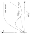
- Figure 2 is a graphical representation of a prior art vehicle launch operation.
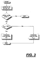
- FIG. 3 is a schematic illustration, in flow chart format, of the control of the present invention.
- the present invention relates to an improved control system/method for vehicle launch operations in vehicles equipped with an at least partially automated mechanical transmission systems wherein master clutch operation is automated for both vehicle launch and dynamic shifting operations.
- master clutch operation is automated for both vehicle launch and dynamic shifting operations.
- FIG. 1 schematically illustrates a vehicular automated mechanical transmission system 10 including an automated multiple-speed change-gear transmission 12 driven by a fuel-controlled engine 14, such as a well-known diesel engine, through a non-positive coupling such as a master friction clutch 16.
- the output of the automated transmission 12 is output shaft 18, which is adapted for driving connection to an appropriate vehicle component, such as the differential of a drive axle, a transfer case or the like, as is well known in the prior art.
- the automated mechanical transmission 10 may be of the clash type, synchronized type and/or blocked type and may be a simple or a compound transmission. Transmissions of this type may be seen by reference to U.S. Patents No. 3,105,395; 4,754,665 and 4,736,643, the disclosures of which are incorporated herein by reference.
- crankshaft 20 of engine 14 will drive the driving plates 22 of master friction clutch 16, which are frictionally engageable to driven plates 24 for driving the input shaft 26 of transmission 12.
- the aforementioned drivetrain components are acted upon and/or monitored by several devices, each of which will be briefly discussed below.
- These devices include a throttle pedal position or throttle opening monitor assembly 28 which senses the operator-set position of the operator-controlled throttling device 30, a fuel control device 32 for controlling the amount of fuel to be supplied to engine 14, an engine speed sensor 34 for sensing the rotational speed of the engine, a clutch operator 36 which engages and disengages master clutch 16 and which also may provide information as to the status of the clutch, an input shaft speed sensor 38 for sensing the rotational speed of transmission input shaft 26, a transmission operator 40 which is effective to shift transmission 12 into a selected gear ratio and to provide a signal indicative of the gear neutral condition and/or the currently engaged gear ratio, and an output shaft speed sensor 42 for sensing the rotational speed of output shaft 18.
- the aforementioned devices supply information to and/or accept command signals from the central processing unit or control 44.
- the central processing unit 44 may include analog and/or digital electronic calculation and logic circuitry, as is well known in the prior art.
- the central processing unit also will receive information from a shift control assembly 46 by which the vehicle operator may select a reverse (R), neutral (N) or forward drive (D) mode of operation of the vehicle.
- a brake pedal sensor 48 also may be provided to provide an input signal (BRK) indicative of operation of the vehicle brakes 50.
- An electrical power source (not shown) and/or a source of pressurized fluid (not shown) provides electrical, hydraulic and/or pneumatic power to the various sensing, operating and/or processing units.
- Drivetrain components and controls therefor of the type described above are known in the prior art and may be appreciated in greater detail by reference to U.S. Patents No. 4,595,986; 4,576,065 and 4,445,939, the disclosures of which are incorporated herein by reference.
- the sensors 28, 34, 36, 38, 42 and 46 may be of any known type of construction for generating analog or digital signals proportional to and/or indicative of the parameter monitored thereby.
- operators 32, 36 and 40 may be of any known electric, hydraulic and/or pneumatic type, or a combination thereof, for executing operations in response to command output signals from the central processing unit 44.
- the central processing unit 44 may be provided with circuitry for differentiating selected input signals. Further, communication between the vehicle engine 14, the throttle position monitor 30 and the central processing unit 44 may be by means of an electronic datalink, preferably conforming to a protocol similar to SAE J1922 and/or SAE J1939.
- the central processing unit will control the rate and extent of engagement of the vehicle master clutch and the amount of fuel supplied to the engine in accordance with predetermined logic rules and as functions of certain control parameters, such as the operators position of the throttle pedal, engine speed, rate of change of engine speed, clutch position and/or the passage of time.
- FIG. 1A schematically illustrates a typical microprocessor-based control unit, such as CPU 44, having input signal receiving means, processing means and output signal generating means.
- FIG. 2 illustrates a vehicle start-from-stop or vehicle launch clutch engagement operation according to a prior art control method.
- engine speed is caused to equal a set value, usually a value associated with the operator's displacement of the throttle pedal, and fueling and clutch engagement then are modulated to maintain the engine speed at substantially this set value while increasingly engaging the clutch. Fueling of the engine is modulated during this operation to achieve these results.
- the line labeled "Fuel (FC)" is the calculated amount of fuel provided to the engine according to the control logic for the start-from-stop operation of Figure 2 and is determined by the central processing unit and not directly by the operator's displacement of the throttle pedal.
- the vehicle launch operation illustrated in Figure 2 is simply representative and many modified and/or alternative vehicle launch logics are known.
- controlling the master clutch and the fueling of the engine in a manner to achieve a smooth and relatively rapid clutch engagement as illustrated in Figure 2 is highly satisfactory for most vehicle launch situations for vehicles equipped with automated mechanical transmission systems of the type illustrated in Figure 1.
- the prior art controls were not as responsive as desired when the vehicle was operating at a relatively slow speed during creeping and maneuvering-type operations or when the operator desires rapid acceleration of the vehicle.
- a torque limit (REF) is determined which will not be abusive to the vehicle driveline under most conditions and which will be sufficient to satisfy the driver during most vehicle operations.
- the torque limit (REF) preferably is about the torque associated with a 10-20% displacement of the throttle pedal.
- the control allows engine torque to rapidly produce torque associated with the 10-20% throttle displacement instead of beginning its ramp at zero and causing a lag in the engine response.
- the throttle pedal has a non-displaced position (0% displacement) corresponding to a minimum amount of fueling to maintain a smooth idling of the engine and may be displaced up to a 100%-displaced position wherein the operator is requesting maximum fueling of the engine. It is also noted that for a given amount of fueling of the engine, the engine will develop a given amount of flywheel torque. In this application, a request for a particular amount of fueling is equivalent to a request for a particular amount of engine flywheel torque.
- the engine during vehicle launch operations, if the amount of engine flywheel torque (engine fueling) requested by the operator's displacement of the throttle pedal is less than or equal to the torque limit (REF), then the engine will be fueled in accordance with the operator-set throttle position. If the amount of engine flywheel torque (engine fueling) requested by the operator's displacement of the throttle pedal exceeds the torque limit, the engine will be fueled in accordance with a calculated amount of fuel (F CALC ), as determined by the standard start-from-stop logic routines.
- F CALC calculated amount of fuel
- the present invention provides a vehicle launch control for a vehicle equipped with an automated mechanical transmission system having improved responsiveness for both low-speed maneuvering operation and intentional rapid acceleration of the vehicle.
Applications Claiming Priority (2)
| Application Number | Priority Date | Filing Date | Title |
|---|---|---|---|
| US370050 | 1995-01-09 | ||
| US08/370,050 US5529548A (en) | 1995-01-09 | 1995-01-09 | Vehicle launch engine fuel control |
Publications (2)
| Publication Number | Publication Date |
|---|---|
| EP0720929A1 true EP0720929A1 (fr) | 1996-07-10 |
| EP0720929B1 EP0720929B1 (fr) | 2003-12-17 |
Family
ID=23458019
Family Applications (1)
| Application Number | Title | Priority Date | Filing Date |
|---|---|---|---|
| EP96300090A Expired - Lifetime EP0720929B1 (fr) | 1995-01-09 | 1996-01-04 | Régulation de l'alimentation de carburant pendant la procédure de démarrage d'un véhicule |
Country Status (5)
| Country | Link |
|---|---|
| US (1) | US5529548A (fr) |
| EP (1) | EP0720929B1 (fr) |
| KR (1) | KR100304242B1 (fr) |
| DE (1) | DE69631075T2 (fr) |
| ES (1) | ES2210338T3 (fr) |
Cited By (5)
| Publication number | Priority date | Publication date | Assignee | Title |
|---|---|---|---|---|
| WO1997035739A1 (fr) * | 1996-03-26 | 1997-10-02 | Robert Bosch Gmbh | Procede et dispositif pour reguler le couple de rotation fourni par une unite d'entrainement |
| GB2399870A (en) * | 2003-03-25 | 2004-09-29 | Eaton Corp | Hill start or aggressive clutch control |
| EP2410163A1 (fr) * | 2010-02-25 | 2012-01-25 | Honda Motor Co., Ltd. | Dispositif de commande de couple de sortie |
| WO2013061128A1 (fr) * | 2011-10-27 | 2013-05-02 | Eaton Corporation | Procédé et système pour déterminer un rapport de transmission pour un groupe motopropulseur comportant une boîte de vitesses auxiliaire |
| CN106571053A (zh) * | 2016-11-07 | 2017-04-19 | 北京小米移动软件有限公司 | 一种启动启停功能的方法及装置 |
Families Citing this family (17)
| Publication number | Priority date | Publication date | Assignee | Title |
|---|---|---|---|---|
| DE19537786A1 (de) * | 1995-10-11 | 1997-04-17 | Bosch Gmbh Robert | Verfahren und Vorrichtung zur Steuerung einer Brennkraftmaschine |
| US5797110A (en) * | 1995-11-17 | 1998-08-18 | Eaton Corporation | Engine torque control |
| US6962551B1 (en) * | 1996-06-19 | 2005-11-08 | Eaton Corporation | Automated transmission system control with zero engine flywheel torque determination |
| US6033340A (en) * | 1996-05-24 | 2000-03-07 | Luk Getriebe-Systeme Gmbh | Method of and apparatus for operating a torque transmitting system in the power train of a motor vehicle |
| JP3787978B2 (ja) * | 1997-09-12 | 2006-06-21 | いすゞ自動車株式会社 | クラッチ断接装置 |
| DE19911736B4 (de) | 1998-03-17 | 2005-12-15 | Honda Giken Kogyo K.K. | Maschinenstopp-Steuersystem für ein Fahrzeug |
| US6157886A (en) * | 1998-08-31 | 2000-12-05 | Eaton Corporation | Method/system for controlling upshifting in an automated mechanical transmission system |
| US6285941B1 (en) | 1998-08-31 | 2001-09-04 | Eaton Corporation | Method/system for controlling shifting in an automated mechanical transmission system |
| US6126569A (en) * | 1999-07-19 | 2000-10-03 | Eaton Corporation | Starting and driveline shock protection control method and system |
| JP4654173B2 (ja) * | 2006-11-16 | 2011-03-16 | 日立オートモティブシステムズ株式会社 | 車両の制御装置 |
| JP4625824B2 (ja) * | 2007-04-25 | 2011-02-02 | ボッシュ株式会社 | 内燃機関出力制御方法及びその装置 |
| US8027780B2 (en) * | 2009-05-01 | 2011-09-27 | GM Global Technology Operations LLC | Method and system for controlling torque during a vehicle launch condition |
| US8437917B2 (en) * | 2010-11-02 | 2013-05-07 | Ford Global Technologies, Llc | Vehicle launch anticipation and adaptation |
| DE102011083332B4 (de) * | 2011-09-23 | 2023-01-26 | Ford Global Technologies, Llc | Verfahren und Vorrichtung zum automatischen Aktivieren bzw. Deaktivieren einer Segel-Betriebsart bei einem Kraftfahrzeug mit Verbrennungsmotor |
| CN102494123A (zh) * | 2011-12-14 | 2012-06-13 | 中国农业大学 | 有级变速器经济挡传动比的确定方法 |
| SE538535C2 (sv) * | 2012-03-27 | 2016-09-13 | Scania Cv Ab | Anordning och förfarande för begränsning av momentuppbyggnadhos en motor hos ett motorfordon |
| KR101393909B1 (ko) * | 2012-09-25 | 2014-05-12 | 현대자동차주식회사 | 차량의 클러치 제어방법 |
Citations (6)
| Publication number | Priority date | Publication date | Assignee | Title |
|---|---|---|---|---|
| DE3243485A1 (de) * | 1982-01-13 | 1983-07-21 | Diesel Kiki Co | Bedienungsautomatik fuer ein mittels einer brennkraftmaschine angetriebenes getriebe |
| DE3334724A1 (de) * | 1983-09-26 | 1985-04-11 | Wabco Westinghouse Fahrzeugbremsen GmbH, 3000 Hannover | Einrichtung zur automatischen oder teilautomatischen steuerung eines motors und einer kupplung eines kraftfahrzeuges |
| DE3421387A1 (de) * | 1984-06-08 | 1985-12-12 | Wabco Westinghouse Fahrzeugbremsen GmbH, 3000 Hannover | Kupplungssteuerung fuer kraftfahrzeug |
| US4873637A (en) * | 1988-02-10 | 1989-10-10 | Eaton Corporation | Control for vehicle start from stop operation |
| US4874070A (en) * | 1988-02-10 | 1989-10-17 | Eaton Corporation | Control for AMT system start from stop operation |
| US5316116A (en) * | 1992-12-09 | 1994-05-31 | Eaton Corporation | Engine control method for use with automatic clutch control |
Family Cites Families (6)
| Publication number | Priority date | Publication date | Assignee | Title |
|---|---|---|---|---|
| US4081065A (en) * | 1976-12-23 | 1978-03-28 | Smyth Robert Ralston | Controlled power clutch |
| US4361060A (en) * | 1978-01-24 | 1982-11-30 | Smyth Robert Ralston | Mechanical automatic transmission |
| US4646891A (en) * | 1985-01-31 | 1987-03-03 | Eaton Corporation | Automatic clutch control |
| US4638898A (en) * | 1985-12-19 | 1987-01-27 | Eaton Corporation | Clutch control system and clutch assembly using same |
| US4922425A (en) * | 1986-04-18 | 1990-05-01 | Eaton Corporation | Method for controlling AMT system including throttle position sensor signal fault detection and tolerance |
| US4714144A (en) * | 1986-04-18 | 1987-12-22 | Eaton Corporation | Method for controlling AMT system start from stop operation |
-
1995
- 1995-01-09 US US08/370,050 patent/US5529548A/en not_active Expired - Lifetime
-
1996
- 1996-01-04 ES ES96300090T patent/ES2210338T3/es not_active Expired - Lifetime
- 1996-01-04 DE DE69631075T patent/DE69631075T2/de not_active Expired - Fee Related
- 1996-01-04 EP EP96300090A patent/EP0720929B1/fr not_active Expired - Lifetime
- 1996-01-09 KR KR1019960000265A patent/KR100304242B1/ko not_active IP Right Cessation
Patent Citations (6)
| Publication number | Priority date | Publication date | Assignee | Title |
|---|---|---|---|---|
| DE3243485A1 (de) * | 1982-01-13 | 1983-07-21 | Diesel Kiki Co | Bedienungsautomatik fuer ein mittels einer brennkraftmaschine angetriebenes getriebe |
| DE3334724A1 (de) * | 1983-09-26 | 1985-04-11 | Wabco Westinghouse Fahrzeugbremsen GmbH, 3000 Hannover | Einrichtung zur automatischen oder teilautomatischen steuerung eines motors und einer kupplung eines kraftfahrzeuges |
| DE3421387A1 (de) * | 1984-06-08 | 1985-12-12 | Wabco Westinghouse Fahrzeugbremsen GmbH, 3000 Hannover | Kupplungssteuerung fuer kraftfahrzeug |
| US4873637A (en) * | 1988-02-10 | 1989-10-10 | Eaton Corporation | Control for vehicle start from stop operation |
| US4874070A (en) * | 1988-02-10 | 1989-10-17 | Eaton Corporation | Control for AMT system start from stop operation |
| US5316116A (en) * | 1992-12-09 | 1994-05-31 | Eaton Corporation | Engine control method for use with automatic clutch control |
Cited By (7)
| Publication number | Priority date | Publication date | Assignee | Title |
|---|---|---|---|---|
| WO1997035739A1 (fr) * | 1996-03-26 | 1997-10-02 | Robert Bosch Gmbh | Procede et dispositif pour reguler le couple de rotation fourni par une unite d'entrainement |
| GB2399870A (en) * | 2003-03-25 | 2004-09-29 | Eaton Corp | Hill start or aggressive clutch control |
| EP2410163A1 (fr) * | 2010-02-25 | 2012-01-25 | Honda Motor Co., Ltd. | Dispositif de commande de couple de sortie |
| EP2410163A4 (fr) * | 2010-02-25 | 2013-01-09 | Honda Motor Co Ltd | Dispositif de commande de couple de sortie |
| WO2013061128A1 (fr) * | 2011-10-27 | 2013-05-02 | Eaton Corporation | Procédé et système pour déterminer un rapport de transmission pour un groupe motopropulseur comportant une boîte de vitesses auxiliaire |
| CN106571053A (zh) * | 2016-11-07 | 2017-04-19 | 北京小米移动软件有限公司 | 一种启动启停功能的方法及装置 |
| US10669980B2 (en) | 2016-11-07 | 2020-06-02 | Beijing Xiaomi Mobile Software Co., Ltd. | Method, apparatus, and system for launching engine start-stop function in vehicles |
Also Published As
| Publication number | Publication date |
|---|---|
| MX9600158A (es) | 1998-07-31 |
| KR100304242B1 (ko) | 2001-11-30 |
| KR960029600A (ko) | 1996-08-17 |
| DE69631075D1 (de) | 2004-01-29 |
| ES2210338T3 (es) | 2004-07-01 |
| DE69631075T2 (de) | 2004-09-16 |
| EP0720929B1 (fr) | 2003-12-17 |
| US5529548A (en) | 1996-06-25 |
Similar Documents
| Publication | Publication Date | Title |
|---|---|---|
| US5529548A (en) | Vehicle launch engine fuel control | |
| EP0686789B1 (fr) | Procédé pour réduire la durée de changement de vitesse dans des groupes motopropulseurs | |
| US5634867A (en) | Main clutch reengagement control for a double clutch downshift | |
| EP1013973B1 (fr) | Contrôle indépendant d'un ralentisseur côte boîte de vitesses et côte moteur pendant le changement de vitesses | |
| EP0244096B1 (fr) | Procédé de commande d'une transmission mécanique automatique, y compris la commande pour l'embrayage et le carburant au départ arrêté | |
| EP1002687B1 (fr) | Commande du couple de ralenti pour l'embrayage principal automatisé d'un véhicule | |
| EP0709246B1 (fr) | Actionnement et mise au point d'embrayage automatisé | |
| EP1000794B1 (fr) | Commande de l'embrayage principal lors du départ d'un véhicule | |
| US5842376A (en) | System and method for decreasing ratio changing time by actuating inertia brake while the master clutch is engaged in electronically enhanced powertrain systems | |
| US6042507A (en) | Torque converter lockup control | |
| EP1020664B1 (fr) | Méthode de commande de rétrogradation d'une boíte de vitesses automatisée | |
| EP1070625B1 (fr) | Méthode et dispositif de commande pour diminuer les chocs de démarrage et dans la chaíne de transmission | |
| EP1151891B1 (fr) | Commande du couple de ralenti pour l'embrayage à sec principal automatisé d'un véhicule | |
| EP1152172B1 (fr) | Commande de montée de vitesse pour transmission automatisée de véhicule | |
| EP0327350B1 (fr) | Procédé pour passer à une vitesse supérieure sans à-coup dans un système automatique ou semi-automatique de transmission mécanique | |
| US6220219B1 (en) | Engine speed control for decreasing engine speed | |
| US6375596B1 (en) | Control to determine input shaft direction of rotation | |
| AU752039B2 (en) | Independent control of transmission-side and engine-side retarding devices during ratio changes | |
| MXPA96000158A (es) | Control de combustible de motor para lanzamientode vehiculo |
Legal Events
| Date | Code | Title | Description |
|---|---|---|---|
| PUAI | Public reference made under article 153(3) epc to a published international application that has entered the european phase |
Free format text: ORIGINAL CODE: 0009012 |
|
| AK | Designated contracting states |
Kind code of ref document: A1 Designated state(s): DE ES FR GB IT SE |
|
| 17P | Request for examination filed |
Effective date: 19961221 |
|
| 17Q | First examination report despatched |
Effective date: 19980701 |
|
| APAB | Appeal dossier modified |
Free format text: ORIGINAL CODE: EPIDOS NOAPE |
|
| APAB | Appeal dossier modified |
Free format text: ORIGINAL CODE: EPIDOS NOAPE |
|
| APAD | Appeal reference recorded |
Free format text: ORIGINAL CODE: EPIDOS REFNE |
|
| APCB | Communication from the board of appeal sent |
Free format text: ORIGINAL CODE: EPIDOS OBAPE |
|
| APCB | Communication from the board of appeal sent |
Free format text: ORIGINAL CODE: EPIDOS OBAPE |
|
| GRAH | Despatch of communication of intention to grant a patent |
Free format text: ORIGINAL CODE: EPIDOS IGRA |
|
| GRAS | Grant fee paid |
Free format text: ORIGINAL CODE: EPIDOSNIGR3 |
|
| GRAA | (expected) grant |
Free format text: ORIGINAL CODE: 0009210 |
|
| AK | Designated contracting states |
Kind code of ref document: B1 Designated state(s): DE ES FR GB IT SE |
|
| REG | Reference to a national code |
Ref country code: GB Ref legal event code: FG4D |
|
| REG | Reference to a national code |
Ref country code: SE Ref legal event code: TRGR |
|
| REF | Corresponds to: |
Ref document number: 69631075 Country of ref document: DE Date of ref document: 20040129 Kind code of ref document: P |
|
| REG | Reference to a national code |
Ref country code: ES Ref legal event code: FG2A Ref document number: 2210338 Country of ref document: ES Kind code of ref document: T3 |
|
| ET | Fr: translation filed | ||
| PLBE | No opposition filed within time limit |
Free format text: ORIGINAL CODE: 0009261 |
|
| STAA | Information on the status of an ep patent application or granted ep patent |
Free format text: STATUS: NO OPPOSITION FILED WITHIN TIME LIMIT |
|
| 26N | No opposition filed |
Effective date: 20040920 |
|
| APAH | Appeal reference modified |
Free format text: ORIGINAL CODE: EPIDOSCREFNO |
|
| PGFP | Annual fee paid to national office [announced via postgrant information from national office to epo] |
Ref country code: FR Payment date: 20060104 Year of fee payment: 11 |
|
| PGFP | Annual fee paid to national office [announced via postgrant information from national office to epo] |
Ref country code: ES Payment date: 20060123 Year of fee payment: 11 |
|
| PGFP | Annual fee paid to national office [announced via postgrant information from national office to epo] |
Ref country code: IT Payment date: 20060131 Year of fee payment: 11 |
|
| REG | Reference to a national code |
Ref country code: FR Ref legal event code: ST Effective date: 20070930 |
|
| REG | Reference to a national code |
Ref country code: ES Ref legal event code: FD2A Effective date: 20070105 |
|
| PG25 | Lapsed in a contracting state [announced via postgrant information from national office to epo] |
Ref country code: FR Free format text: LAPSE BECAUSE OF NON-PAYMENT OF DUE FEES Effective date: 20070131 |
|
| PG25 | Lapsed in a contracting state [announced via postgrant information from national office to epo] |
Ref country code: ES Free format text: LAPSE BECAUSE OF NON-PAYMENT OF DUE FEES Effective date: 20070105 |
|
| APBU | Appeal procedure closed |
Free format text: ORIGINAL CODE: EPIDOSNNOA9O |
|
| PGFP | Annual fee paid to national office [announced via postgrant information from national office to epo] |
Ref country code: DE Payment date: 20090130 Year of fee payment: 14 |
|
| PGFP | Annual fee paid to national office [announced via postgrant information from national office to epo] |
Ref country code: GB Payment date: 20081211 Year of fee payment: 14 |
|
| PGFP | Annual fee paid to national office [announced via postgrant information from national office to epo] |
Ref country code: SE Payment date: 20090108 Year of fee payment: 14 |
|
| PG25 | Lapsed in a contracting state [announced via postgrant information from national office to epo] |
Ref country code: IT Free format text: LAPSE BECAUSE OF NON-PAYMENT OF DUE FEES Effective date: 20070104 |
|
| GBPC | Gb: european patent ceased through non-payment of renewal fee |
Effective date: 20100104 |
|
| EUG | Se: european patent has lapsed | ||
| PG25 | Lapsed in a contracting state [announced via postgrant information from national office to epo] |
Ref country code: DE Free format text: LAPSE BECAUSE OF NON-PAYMENT OF DUE FEES Effective date: 20100803 |
|
| PG25 | Lapsed in a contracting state [announced via postgrant information from national office to epo] |
Ref country code: GB Free format text: LAPSE BECAUSE OF NON-PAYMENT OF DUE FEES Effective date: 20100104 |
|
| PG25 | Lapsed in a contracting state [announced via postgrant information from national office to epo] |
Ref country code: SE Free format text: LAPSE BECAUSE OF NON-PAYMENT OF DUE FEES Effective date: 20100105 |