EP0720752B1 - Fiber optic connector with strain relief means - Google Patents
Fiber optic connector with strain relief means Download PDFInfo
- Publication number
- EP0720752B1 EP0720752B1 EP94929303A EP94929303A EP0720752B1 EP 0720752 B1 EP0720752 B1 EP 0720752B1 EP 94929303 A EP94929303 A EP 94929303A EP 94929303 A EP94929303 A EP 94929303A EP 0720752 B1 EP0720752 B1 EP 0720752B1
- Authority
- EP
- European Patent Office
- Prior art keywords
- strain relief
- relief member
- rigid
- fiber optic
- deformable
- Prior art date
- Legal status (The legal status is an assumption and is not a legal conclusion. Google has not performed a legal analysis and makes no representation as to the accuracy of the status listed.)
- Expired - Lifetime
Links
- 239000000835 fiber Substances 0.000 title claims description 44
- 230000001681 protective effect Effects 0.000 claims description 26
- 239000013307 optical fiber Substances 0.000 claims description 17
- 230000037431 insertion Effects 0.000 claims 1
- 238000003780 insertion Methods 0.000 claims 1
- 230000002035 prolonged effect Effects 0.000 claims 1
- 239000000463 material Substances 0.000 description 7
- 239000000872 buffer Substances 0.000 description 3
- 229910052751 metal Inorganic materials 0.000 description 3
- 239000002184 metal Substances 0.000 description 3
- 239000004033 plastic Substances 0.000 description 3
- 229920003023 plastic Polymers 0.000 description 3
- 239000004831 Hot glue Substances 0.000 description 1
- 229920000271 Kevlar® Polymers 0.000 description 1
- 239000004743 Polypropylene Substances 0.000 description 1
- 239000000853 adhesive Substances 0.000 description 1
- 230000001070 adhesive effect Effects 0.000 description 1
- 229910052782 aluminium Inorganic materials 0.000 description 1
- XAGFODPZIPBFFR-UHFFFAOYSA-N aluminium Chemical compound [Al] XAGFODPZIPBFFR-UHFFFAOYSA-N 0.000 description 1
- 229910010293 ceramic material Inorganic materials 0.000 description 1
- 230000000881 depressing effect Effects 0.000 description 1
- 229920006332 epoxy adhesive Polymers 0.000 description 1
- 229920002457 flexible plastic Polymers 0.000 description 1
- 239000004761 kevlar Substances 0.000 description 1
- -1 polypropylene Polymers 0.000 description 1
- 229920001155 polypropylene Polymers 0.000 description 1
Images


Classifications
-
- G—PHYSICS
- G02—OPTICS
- G02B—OPTICAL ELEMENTS, SYSTEMS OR APPARATUS
- G02B6/00—Light guides; Structural details of arrangements comprising light guides and other optical elements, e.g. couplings
- G02B6/24—Coupling light guides
- G02B6/36—Mechanical coupling means
- G02B6/38—Mechanical coupling means having fibre to fibre mating means
- G02B6/3807—Dismountable connectors, i.e. comprising plugs
- G02B6/3887—Anchoring optical cables to connector housings, e.g. strain relief features
- G02B6/3888—Protection from over-extension or over-compression
Definitions
- Optical fibers are commonly provided in protective cables. Inside these cables the fibers are often surrounded by protective filaments. Such protective filaments may be of a material such as an arimide. Such filaments provide multiple forms of protection to the fiber. Besides providing mechanical protection to the fiber inside the cable, they may be used to provide strain relief when the fiber emerges from the cable and is inserted into a connecter.
- strain relief is required to isolate the fiber which is typically firmly held, either by an adhesive or a mechanical clamp, at the front of the connector, i.e., the end of the connector where the fiber terminates from mechanical stress. Strain relief is achieved by mechanically clamping the protective filaments to the connector.
- a fiber optic connector which comprises a collapsible crimp ring and a connector body.
- a rigid strain relief member is disposed at the rear of the connector body and can be used in connection with the crimp ring for gripping protective filaments of a fiber optic cable.
- a deformable strain relief member is provided which can be used for gripping a buffered optical fiber when deformed by the crimp ring.
- a bore extends all the way through the connector body, the rigid strain relief member and the deformable strain relief member.
- a fiber optic connector uses a collapsible crimp ring, a rigid strain relief member, and a deformable strain relief member.
- the rigid strain relief member in conjunction with the crimp ring, will grip protective filaments from an optical fiber cable if they are available.
- the deformable stain relief member in conjunction with the crimp ring, will grip a buffered optical fiber from the cable when deformed by the crimp ring.
- the outer diameter of the deformable strain relief member in its undeformed state is greater than that of the rigid strain relief member.
- an optical fiber connector 10 includes a bayonet connector cover, 12, a ferrule, 14, and a rigid strain relief member, 16. Inserted into rigid strain relief member 16 is a flexible strain relief member, 18. A connector body 17, preferably integral with rigid strain relief member 16, underlies bayonet cover 12 and cannot be seen in Figure 1 (see Fig. 5).
- Bayonet cover 12 is generally of either a metal or a plastic material.
- Ferrule 14 is generally either of a plastic or a ceramic material, although metal ferrules are also used. As shown ferrule 14 is cylindrical, like the ferules used in "ST" and "SC" connectors, although any a ferrule of any shape will work with the invention. For example, ferrule 14 could instead be a truncated cone such as is used in a biconic connector.
- Rigid strain relief member 16 is generally of a hard plastic, although any rigid material will work.
- Deformable strain relief member 18 is generally of a flexible plastic material such as low density polypropylene. As will become apparent later, it is important that deformable strain relief member 18 have a greater diameter than rigid strain relief member 16.
- a bore 20 runs through deformable strain relief member 18, rigid strain relief member 16, the connector body 17, and ferrule 14.
- an optical fiber, 22, is inserted in bore 20.
- optical fiber 22 is slid all the way through bore 20 so that its end face is flush with the end face of ferrule 14 and its protective buffer extends into deformable strain relief member 18.
- the fiber is fastened in place by any of a variety of means.
- the most commonly used method is an epoxy adhesive.
- a hot melt adhesive may be used.
- the connector shown in Figure 2 includes apparatus 24 for mechanically clamping a fiber in the connector. Clamping apparatus 24 is more fully described in WO-A-93/21547.
- Crimp ring 26 is collapsed.
- the use of the term “crimp ring” should not be taken to imply that it must be round.
- Crimp ring 26 is preferably of a metal such as aluminum. When crimp ring 26 collapses, it causes deformable strain relief 18 to be collapsed as well. The presence of slots 28A, 28B, 28C, and 28D in the formable strain relief member 18 help it to collapse in an even manner. Slots 28A, 28B, 28C, and 28D are not required for proper operation of the invention but generally will provide superior performance.
- Deformable strain relief member 18 and crimp ring 26 are sized such that deformable strain relief 18 will tightly grip a buffered optical fiber after collapse.
- Deformable strain relief member 18 must be substantially greater in diameter than rigid strain relief member 16 in order to insure that rigid strain relief member 16 not interfere with the collapse of deformable strain relief member 18.
- Figure 3 shows the optical fiber connector of the invention utilized in conjunction with an optical fiber that is sheathed with a protective material such as arimide filaments.
- a protective material such as arimide filaments.
- a commonly used protective material is sold under the trademark "Kevlar” by E. I. duPont de Nemours.
- the fiber is inserted through bore 20 and fastened in connector 10.
- those filaments, 30, are inserted into the gap between crimp ring 26 and rigid strain relief member 16 and flexible strain relief member 18 prior to the collapse of crimp ring 26.
- protective filaments 30 are held tightly between crimp ring 26 and rigid strain relief member 16.
- rigid strain relief member 16 may be provided with a series of ridges and grooves in order to cause it to more tightly hold protective filaments 30.
- a connector according to the invention may be used with fibers that are filament protected as well as those that are not with no change in parts.
- the fiber may be further protected by adding a protective boot, 32, over crimp ring 26 and strain relief members 16 and 18.
- a protective boot may be used with either a buffered fiber without protective filaments, as shown in Figure 2, or a fiber with protective filaments as shown in Figure 3.
- FIG. 5 is a cutaway side view of a connector for optical fibers according to the invention.
- connector 10 includes bayonet cover 12.
- rigid strain relief member 16 is integral with connector body 17, which extends all the way through bayonet cover 12 and holds ferrule 14 in place.
- Deformable strain relief member 18 is inserted into rigid strain relief member 16 and locked in place.
- Crimp ring 26 encircles a portion of rigid strain relief member 16 and a portion of flexible strain relief member 18.
- Figure 5 shows a spring 34.
- Spring 34 is required to comply with standards in order to make the fiber optic connector according to the invention compatible with other connectors.
- Figure 5 also shows clamping element 36, which is engaged by depressing clamping apparatus 24 of Figure 2.
- Clamping element 36 includes a pair of grooves that, when clamping element 36 is engaged, form a bore 38 in alignment with bore 20.
- Optical fiber 22 of Figure 2 is pinched in bore 38 and held in place in connector 10.
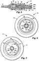
- Figure 6 shows a end view of connector 10 prior to the collapse of crimp ring 26.
- deformable strain relief member 18 has a bore 20 with optical fiber 22 inserted therein.
- deformable strain relief member 18 has slots 28 to insure that it deforms in the manner intended.
- Figure 7 is the same view as Figure 6 following the collapse of crimp ring 26. As may be seen, deformable strain relief member 18 is fully collapsed and now tightly holds fiber 22. If the fiber shown in Figure 7 had come from a cable including protective filaments, those filaments would be pinched between crimp ring 26 and rigid strain relief member 16.
Landscapes
- Physics & Mathematics (AREA)
- General Physics & Mathematics (AREA)
- Optics & Photonics (AREA)
- Mechanical Coupling Of Light Guides (AREA)
- Cable Accessories (AREA)
Description
Claims (5)
- A fiber optic connector comprising:a connector body (17),a rigid strain relief member (16) and a deformable strain relief member (18) disposed one after the other at the rear of said connector body (17),wherein each of said connector body (17), said rigid strain relief member (16), and said deformable strain relief member (18) has a bore (20) therethrough for the insertion therein, up to the front of said connector body (17), of a buffered optical fiber (22) from a fiber optic cable, anda collapsible crimp ring (26), encircling at least a portion of each of said rigid and said deformable strain relief members (16, 18), for gripping protective filaments (30) from said fiber optic cable in conjunction with said rigid strain relief member and for deforming said deformable strain relief member (18) so that thus deformed strain relief member (18) grips said buffered optical fiber inserted therein,
characterized in thatsaid deformable strain relief member (18) has in its undeformed state a greater outer diameter than said rigid strain relief member (16). - A fiber optic connector according to claim 1, characterized in that said deformable strain relief member (18) is provided with slots (28A-28D) connected to the bore (20) for supporting the deformable strain relief member (18) to collapse in a substantially even manner.
- A fiber optic connector according to claim 1 or 2, characterized in that said rigid strain relief member (16) is provided with ridges and grooves for causing it to more tightly hold said protective filaments from said cable.
- A fiber optic connector according to any one of claims 1 to 3, characterized in that said rigid strain relief member (16) is integral with said connector body (17).
- A fiber optic connector according to any one of claims 1 to 4, characterized in that said deformable strain relief member (18) is frontwardly prolonged by a bored portion of lower outer diameter which is inserted into said rigid strain relief member (16) and locked in place.
Applications Claiming Priority (3)
| Application Number | Priority Date | Filing Date | Title |
|---|---|---|---|
| US08/125,563 US5425119A (en) | 1993-09-23 | 1993-09-23 | Connector strain relief for optical fiber |
| US125563 | 1993-09-23 | ||
| PCT/US1994/010745 WO1995008784A1 (en) | 1993-09-23 | 1994-09-22 | Connector strain relief for optical fiber |
Publications (2)
| Publication Number | Publication Date |
|---|---|
| EP0720752A1 EP0720752A1 (en) | 1996-07-10 |
| EP0720752B1 true EP0720752B1 (en) | 2000-04-19 |
Family
ID=22420316
Family Applications (1)
| Application Number | Title | Priority Date | Filing Date |
|---|---|---|---|
| EP94929303A Expired - Lifetime EP0720752B1 (en) | 1993-09-23 | 1994-09-22 | Fiber optic connector with strain relief means |
Country Status (6)
| Country | Link |
|---|---|
| US (1) | US5425119A (en) |
| EP (1) | EP0720752B1 (en) |
| JP (1) | JPH09503072A (en) |
| DE (1) | DE69424057T2 (en) |
| ES (1) | ES2145157T3 (en) |
| WO (1) | WO1995008784A1 (en) |
Families Citing this family (19)
| Publication number | Priority date | Publication date | Assignee | Title |
|---|---|---|---|---|
| US6056056A (en) * | 1995-03-31 | 2000-05-02 | Durst; Douglas G. | Whipstock mill |
| US5812718A (en) * | 1996-03-27 | 1998-09-22 | Minnesota Mining And Manufacturing Company | Method for connecting optical fibers and the interconnection |
| US6139195A (en) * | 1996-05-22 | 2000-10-31 | Minnesota Mining And Manufacturing Company | Strain relief for a coated optical fiber in a connector |
| US6074103A (en) * | 1996-10-15 | 2000-06-13 | Sdl, Inc. | Aligning an optical fiber with electroluminescent semiconductor diodes and other optical components |
| JP3225202B2 (en) * | 1997-01-24 | 2001-11-05 | ヒロセ電機株式会社 | Optical connector |
| US5732175A (en) * | 1997-01-31 | 1998-03-24 | Litecom, Inc. | Connecting system for fiber optic termination |
| US5857046A (en) * | 1997-02-12 | 1999-01-05 | The Whitaker Corporation | Strain relief |
| US5923804A (en) * | 1997-03-31 | 1999-07-13 | Siecor Corporation | Fiber optic connector and an associated method of fabrication |
| GB2326636B (en) * | 1997-06-28 | 2000-11-01 | Secr Defence | Sol-Gel route to transparent metal oxide films |
| JP3756703B2 (en) | 1999-08-05 | 2006-03-15 | 矢崎総業株式会社 | Optical connector |
| US6601997B2 (en) * | 2001-04-17 | 2003-08-05 | Fci Americas Technology, Inc. | Fiber optic cable guide boot |
| US6817780B2 (en) * | 2003-01-15 | 2004-11-16 | Fci Americas Technology, Inc. | Guide boot for a fiber-optic cable |
| US7682088B2 (en) * | 2006-06-19 | 2010-03-23 | Commscope, Inc. Of North Carolina | Non-halogen fiber optic connectors |
| US20090199597A1 (en) * | 2008-02-07 | 2009-08-13 | Danley Jeffrey D | Systems and methods for collapsing air lines in nanostructured optical fibers |
| US8622481B2 (en) | 2011-01-25 | 2014-01-07 | Joy Mm Delaware, Inc. | Fiber optic cable protection in a mining system |
| US9989187B2 (en) | 2013-06-10 | 2018-06-05 | Delavan Inc. | Tube strain relievers |
| US9739954B1 (en) | 2016-02-19 | 2017-08-22 | Corning Optical Communications LLC | Strain relief device for a fiber optic connector |
| WO2019195652A1 (en) * | 2018-04-06 | 2019-10-10 | US Conec, Ltd | Flexible push-pull boot and crimp body for fiber optic connector |
| WO2020214433A1 (en) | 2019-04-16 | 2020-10-22 | Corning Research & Development Corporation | Fiber optic connectors with funnel-shaped boots and methods of installing the same |
Family Cites Families (20)
| Publication number | Priority date | Publication date | Assignee | Title |
|---|---|---|---|---|
| US4148557A (en) * | 1977-07-11 | 1979-04-10 | Hewlett-Packard Company | Adjustable fiber optic connector |
| DE2943180C2 (en) * | 1979-10-25 | 1986-04-24 | Bunker Ramo Corp., Oak Brook, Ill. | Fiber optic connector |
| US4447121A (en) * | 1981-11-06 | 1984-05-08 | Amp Incorporated | Connector for fiber optic member |
| CA1240184A (en) * | 1982-05-24 | 1988-08-09 | Amp Inc | Connector for fiber optic member |
| US4773725A (en) * | 1982-05-24 | 1988-09-27 | Amp Incorporated | Termination of a fiber optic transmission member and method therefore |
| US4668045A (en) * | 1983-01-03 | 1987-05-26 | Gte Laboratories Incorporated | Optical fiber centering device |
| SE436940B (en) * | 1983-05-26 | 1985-01-28 | Ericsson Telefon Ab L M | DEVICE FOR HEALING TO THE END OF AN OPTICAL FIBER IN A SHELTER |
| US4679895A (en) * | 1984-08-31 | 1987-07-14 | Amp Incorporated | Adhesiveless optical fiber connector |
| JPS6188208A (en) * | 1984-10-08 | 1986-05-06 | Nec Corp | Optical fiber connector |
| US4930856A (en) * | 1986-02-14 | 1990-06-05 | Pilling Co. | Termination for flexible light-transmitting cables |
| DE3842368A1 (en) * | 1988-12-16 | 1990-06-21 | Quante Ag | DETACHABLE CONNECTOR FOR COUPLING TWO LIGHTWAVE LADDERS |
| US5142602A (en) * | 1989-09-05 | 1992-08-25 | Labinal Components & Systems, Inc. | Fiber optic connectors |
| US4984865A (en) * | 1989-11-17 | 1991-01-15 | Minnesota Mining And Manufacturing Company | Thermoplastic adhesive mounting apparatus and method for an optical fiber connector |
| US5062683A (en) * | 1990-07-09 | 1991-11-05 | Molex Incorporated | Strain relief connector for optical fiber |
| US5140661A (en) * | 1991-08-06 | 1992-08-18 | G & H Technology, Inc. | Optical fiber terminus |
| US5166997A (en) * | 1991-10-04 | 1992-11-24 | Norland Products Incorporated | Cable retention system |
| US5222169A (en) * | 1992-02-18 | 1993-06-22 | Foxconn International, Inc. | Optical fiber connector assembly |
| US5202942A (en) * | 1992-04-03 | 1993-04-13 | Amp Incorporated | Cable termination member for fiber optic connectors having improved strain relief |
| US5224187A (en) * | 1992-04-29 | 1993-06-29 | Scientific-Atlanta, Inc. | Fiber optic cable connectors providing strain relief |
| US5321784A (en) * | 1993-02-18 | 1994-06-14 | Minnesota Mining And Manufacturing Company | Pull-proof, modular fiber optic connector system |
-
1993
- 1993-09-23 US US08/125,563 patent/US5425119A/en not_active Expired - Fee Related
-
1994
- 1994-09-22 EP EP94929303A patent/EP0720752B1/en not_active Expired - Lifetime
- 1994-09-22 ES ES94929303T patent/ES2145157T3/en not_active Expired - Lifetime
- 1994-09-22 WO PCT/US1994/010745 patent/WO1995008784A1/en active IP Right Grant
- 1994-09-22 JP JP7509940A patent/JPH09503072A/en active Pending
- 1994-09-22 DE DE69424057T patent/DE69424057T2/en not_active Expired - Fee Related
Also Published As
| Publication number | Publication date |
|---|---|
| DE69424057T2 (en) | 2000-12-14 |
| DE69424057D1 (en) | 2000-05-25 |
| WO1995008784A1 (en) | 1995-03-30 |
| US5425119A (en) | 1995-06-13 |
| ES2145157T3 (en) | 2000-07-01 |
| EP0720752A1 (en) | 1996-07-10 |
| JPH09503072A (en) | 1997-03-25 |
Similar Documents
| Publication | Publication Date | Title |
|---|---|---|
| EP0720752B1 (en) | Fiber optic connector with strain relief means | |
| EP0563995B1 (en) | Optical fiber connector | |
| EP2193395B1 (en) | Strain-relief assemblies and methods for a field-installable fiber optic connector | |
| EP1245980B1 (en) | Furcation kit for optical fiber cable | |
| US20190041588A1 (en) | Field installable optical fiber connector for fiber optic cables with rigid strength members | |
| US6419402B1 (en) | Fiber optic connector and method for assembling | |
| US4626067A (en) | Method of breaking out and terminating fiber optic elements from a multifiber cable | |
| CA2461022C (en) | Fiber optic plug | |
| US4812006A (en) | Fiber optic connector with colley retention | |
| US20020164130A1 (en) | Fiber optic module attachment including a fiber locating connector | |
| US4526438A (en) | Alignment sleeve for fiber optic connectors | |
| EP0029601B1 (en) | Optical fiber cable termination assembly | |
| EP0061243B1 (en) | Optical waveguide connector | |
| EP0602958A2 (en) | Fiber optic assembly and crimp sleeve therefor | |
| US5073043A (en) | Cable jacket restraint in optical fiber connectors | |
| WO1993024852A1 (en) | Fiber optic connector | |
| EP1680698B1 (en) | Anchor for fiber optic cable | |
| WO2018137172A1 (en) | Field terminable optical fiber connector | |
| US20240151906A1 (en) | Fusion spliced optical connector | |
| JP2661960B2 (en) | Multi-core optical cord branch | |
| JPH04343305A (en) | Optical fiber cable connector |
Legal Events
| Date | Code | Title | Description |
|---|---|---|---|
| PUAI | Public reference made under article 153(3) epc to a published international application that has entered the european phase |
Free format text: ORIGINAL CODE: 0009012 |
|
| 17P | Request for examination filed |
Effective date: 19960309 |
|
| AK | Designated contracting states |
Kind code of ref document: A1 Designated state(s): DE ES FR GB IT |
|
| 17Q | First examination report despatched |
Effective date: 19970306 |
|
| GRAG | Despatch of communication of intention to grant |
Free format text: ORIGINAL CODE: EPIDOS AGRA |
|
| RTI1 | Title (correction) |
Free format text: FIBER OPTIC CONNECTOR WITH STRAIN RELIEF MEANS |
|
| GRAG | Despatch of communication of intention to grant |
Free format text: ORIGINAL CODE: EPIDOS AGRA |
|
| GRAH | Despatch of communication of intention to grant a patent |
Free format text: ORIGINAL CODE: EPIDOS IGRA |
|
| GRAH | Despatch of communication of intention to grant a patent |
Free format text: ORIGINAL CODE: EPIDOS IGRA |
|
| GRAA | (expected) grant |
Free format text: ORIGINAL CODE: 0009210 |
|
| AK | Designated contracting states |
Kind code of ref document: B1 Designated state(s): DE ES FR GB IT |
|
| REF | Corresponds to: |
Ref document number: 69424057 Country of ref document: DE Date of ref document: 20000525 |
|
| ET | Fr: translation filed | ||
| REG | Reference to a national code |
Ref country code: ES Ref legal event code: FG2A Ref document number: 2145157 Country of ref document: ES Kind code of ref document: T3 |
|
| ITF | It: translation for a ep patent filed | ||
| PLBE | No opposition filed within time limit |
Free format text: ORIGINAL CODE: 0009261 |
|
| STAA | Information on the status of an ep patent application or granted ep patent |
Free format text: STATUS: NO OPPOSITION FILED WITHIN TIME LIMIT |
|
| 26N | No opposition filed | ||
| PGFP | Annual fee paid to national office [announced via postgrant information from national office to epo] |
Ref country code: FR Payment date: 20010831 Year of fee payment: 8 Ref country code: DE Payment date: 20010831 Year of fee payment: 8 |
|
| PGFP | Annual fee paid to national office [announced via postgrant information from national office to epo] |
Ref country code: GB Payment date: 20010904 Year of fee payment: 8 |
|
| PGFP | Annual fee paid to national office [announced via postgrant information from national office to epo] |
Ref country code: ES Payment date: 20011009 Year of fee payment: 8 |
|
| REG | Reference to a national code |
Ref country code: GB Ref legal event code: IF02 |
|
| PG25 | Lapsed in a contracting state [announced via postgrant information from national office to epo] |
Ref country code: GB Free format text: LAPSE BECAUSE OF NON-PAYMENT OF DUE FEES Effective date: 20020922 |
|
| PG25 | Lapsed in a contracting state [announced via postgrant information from national office to epo] |
Ref country code: ES Free format text: LAPSE BECAUSE OF NON-PAYMENT OF DUE FEES Effective date: 20020923 |
|
| PG25 | Lapsed in a contracting state [announced via postgrant information from national office to epo] |
Ref country code: DE Free format text: LAPSE BECAUSE OF NON-PAYMENT OF DUE FEES Effective date: 20030401 |
|
| GBPC | Gb: european patent ceased through non-payment of renewal fee |
Effective date: 20020922 |
|
| PG25 | Lapsed in a contracting state [announced via postgrant information from national office to epo] |
Ref country code: FR Free format text: LAPSE BECAUSE OF NON-PAYMENT OF DUE FEES Effective date: 20030603 |
|
| REG | Reference to a national code |
Ref country code: FR Ref legal event code: ST |
|
| REG | Reference to a national code |
Ref country code: ES Ref legal event code: FD2A Effective date: 20031011 |
|
| PG25 | Lapsed in a contracting state [announced via postgrant information from national office to epo] |
Ref country code: IT Free format text: LAPSE BECAUSE OF NON-PAYMENT OF DUE FEES Effective date: 20050922 |