EP0720076A2 - Device for displaying and centring the thermal and dynamic vertical winds - Google Patents
Device for displaying and centring the thermal and dynamic vertical winds Download PDFInfo
- Publication number
- EP0720076A2 EP0720076A2 EP95810811A EP95810811A EP0720076A2 EP 0720076 A2 EP0720076 A2 EP 0720076A2 EP 95810811 A EP95810811 A EP 95810811A EP 95810811 A EP95810811 A EP 95810811A EP 0720076 A2 EP0720076 A2 EP 0720076A2
- Authority
- EP
- European Patent Office
- Prior art keywords
- speed
- vector
- display
- wind
- amount
- Prior art date
- Legal status (The legal status is an assumption and is not a legal conclusion. Google has not performed a legal analysis and makes no representation as to the accuracy of the status listed.)
- Withdrawn
Links
Images

Classifications
-
- G—PHYSICS
- G01—MEASURING; TESTING
- G01P—MEASURING LINEAR OR ANGULAR SPEED, ACCELERATION, DECELERATION, OR SHOCK; INDICATING PRESENCE, ABSENCE, OR DIRECTION, OF MOVEMENT
- G01P5/00—Measuring speed of fluids, e.g. of air stream; Measuring speed of bodies relative to fluids, e.g. of ship, of aircraft
Definitions
- the object of the invention is therefore to provide a device which permanently displays the direction and strength of the wind and the amount of the average travel speed without the installation of a travel meter on the aircraft.
- the advantages achieved by the invention are that the pilot always takes into account the influence of the wind and can therefore take into account or use the prevailing winds, for example during competition and cross-country flights. For this information, which is always available, he will invest neither flight time nor attention, and will be able to react immediately to the creeping dangers of the weather.
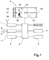
- the block diagram shown in FIG. 1 of the device for determining and displaying the wind vector and the travel of an aircraft consists of a signal processing device 4, a control device 5, a display device 6, a control unit and various memories as well as inputs and outputs.
- a radio receiver with antenna 1 is used to generate signals which correspond to the geographic position and the vector of the basic speed.
- Such a marketable device is, for example, the GPS module for satellite navigation, the Earth's global positioning system (NAVSTAR Global Positioning System) from the Ministry of Defense the United States, which allows satellite data for civilian use.
- FIG. 3 shows some basic speed vectors of a flight minute when circling, for example measured with satellite navigation.
- all vectors of a north-oriented polar coordinate system are displayed. If there was no wind, the basic speed, assuming constant driving, would be the same in all directions. Accordingly, the envelope of the ideally measured vectors would be a circle, the center of which coincides with the vector base.
- the basic speed vectors in FIG. 4 become smaller with a headwind component and those transverse to the wind and with a co-wind component are greater than the travel speed.
- the envelope curve in FIG. 5 is again a Circle whose center is shifted from the center of the polar coordinate system around the wind vector.
- step (b) the wind calculation is limited to a height range between Hu and Ho, analogous to the barometric height. If amounts of the velocity vectors as a function of the course are present in the azimuth sector dK ⁇ dKmax, in step (d) the average advertising is made to a VgMW (K) per course. If condition (c) is not met, the calculation (from "a") is repeated. In step (e), the assignment of the basic speed vectors is carried out for all courses (0 ...
Abstract
Description
Die Erfindung betrifft ein Verfahren zur Ermittlung und Anzeige des Windvektors und der Fahrt eines Luftfahrzeuges nach Anspruch 8 und eine Vorrichtung zur Durchführung des Verfahrens, gemäss der Ansprüche 1 bis 7.The invention relates to a method for determining and displaying the wind vector and the travel of an aircraft according to
Im Luftsport wird das "Schätzen" für die Beurteilung des Windvektors gelehrt. So sind für den Piloten der Versatz von Rauchschwaden, die Krauselung offener Gewässer, das Wiegen der Gräser, das Zittern des Laubwerks der Bäume und der Zug der Wolken Zeichen ständiger Beobachtung für die Anzeige der Windrichtung und der Windstärke. Für die Quantifizierung dient die Ermittlung des Abdriften des Luftfahrzeuges mit Kursfliegen, Messung der Zeit, Kartenvergleich der Positionen und Berechnung der Windgeschwindigkeit mit Hilfe des Winddreiecks. Neulich ist die Vereinfachung dieses Verfahrens mit Geräten der Satellitennavigation möglich geworden. Die Anwendung dieser Verfahren ist wesentlich einfacher, bedingt jedoch weiterhin das Kursfliegen ohne Rücksicht auf die Auf- und Abwinde und beansprucht während der Messung die Aufmerksammkeit des Piloten stark. Das eigentliche Problem beider Verfahren bleibt; um die Änderungen der Windrichtung oder die Windgeschwindigkeit zu erkennen, ist die Prozedur zu wiederholen.In air sports the "guessing" for the assessment of the wind vector is taught. For the pilot, the offset of smoke plumes, the curling of open water, the weighing of the grasses, the trembling of the foliage of the trees and the train of clouds are signs of constant observation for the indication of the wind direction and the wind force. For the quantification, the determination of the drift of the aircraft with course flies, measurement of the time, map comparison of the positions and calculation of the wind speed with the help of the wind triangle is used. The simplification of this procedure has recently become possible with devices of satellite navigation. The use of these methods is much easier, but still requires course flying regardless of the up and down winds and places a great deal of attention on the pilot during the measurement. The real problem with both methods remains; Repeat the procedure to detect changes in wind direction or wind speed.
Es sind zahlreiche Unfälle bekannt, deren Grund die Missachtung des herrschenden Windes, Strömungsabriss der Tragflächen, oder auf die Überforderung der Aufmerksamkeit des Piloten zurückzuführen sind.
Um gefährliche Flugzustände, wie das Absacken und das Abkippen (stall and spin) der Tragfläche wegen Strömungsabriss zu vermeiden ist für den Piloten die Beachtung der Mindestfluggeschwindigkeit, die im Rückenwind entsprechend der Windgeschwindigkeit höher ist (!), von entscheidender Bedeutung. In den meisten Sparten der Fliegerei ist deshalb die Installation eines Fahrtmessers am Luftfahrzeug vorgeschrieben. In der Tuchfliegerei ist die Verwendung von Instrumenten Sache des Piloten, nicht zuletzt deshalb, weil das Anbringen einer Sonde im Vorfeld der Tragfläche umständlich und vor der Kappe eines Gleitschirmes kaum möglich ist. Für die Gleitschirme ist die Verwendung von Flügelrad-Drehzahlmessern (Anemometer) bekannt, die der Pilot herabhängen lässt. Das Einholen des Sensors vor der Landung ist umständlich und die Anzeige beim Pendeln des Schirmes oder im Kurvenflug ungenau. Darum fliegen viele Piloten wie zur Zeit Lilienthals lieber "gefühlsmässig".Numerous accidents are known, the reason for which is the disregard of the prevailing wind, stalling of the wings, or the excessive attention of the pilot.
To avoid dangerous flight conditions, such as sagging and stalling of the wing due to stall, it is of crucial importance for the pilot to observe the minimum flight speed, which is higher (!) In the tailwind according to the wind speed. In most branches of aviation, the installation of an odometer on the aircraft is therefore mandatory. In cloth flying, the use of instruments is a matter for the pilot, not least because it is cumbersome to attach a probe in advance of the wing and hardly possible in front of a paraglider's cap. For paragliders, the use of impeller tachometers (anemometers) is known, which the pilot lets hang down. Getting the sensor in before landing is cumbersome and the display is inaccurate when the wing is swinging or cornering. That is why many pilots like Lilienthal's time prefer to fly "emotionally".
Aufgabe der Erfindung ist daher, eine Vorrichtung zu schaffen, die ohne Installation eines Fahrtmessers am Fluggerät, die Richtung und Stärke des Windes permanent und den Betrag der mittleren Fahrtgeschwindigkeit anzeigt.The object of the invention is therefore to provide a device which permanently displays the direction and strength of the wind and the amount of the average travel speed without the installation of a travel meter on the aircraft.
Die vorliegende Erfindung stellt sich die Aufgabe, die genannten Nachteile zu beseitigen.The object of the present invention is to eliminate the disadvantages mentioned.
Erfindungsgemäss wird diese Aufgabe gelöst durch die kennzeichnenden Merkmale des Anspruchs 1 und 8.According to the invention, this object is achieved by the characterizing features of
Die durch die Erfindung erreichten Vorteile sind nebst der Erhöhung der Flugsicherheit, dass der Pilot den Einfluss des Windes stets berücksichtigen und darum beispielsweise bei Wettbewerb und Streckenflügen die herrschende Winde berücksichtigen, oder nützen kann. Für diese Informationen, die ständig vorliegen, wird er weder Flugzeit noch Aufmerksamkeit investieren, und auf schleichende Gefahren des Wetters sofort reagieren können.In addition to increasing flight safety, the advantages achieved by the invention are that the pilot always takes into account the influence of the wind and can therefore take into account or use the prevailing winds, for example during competition and cross-country flights. For this information, which is always available, he will invest neither flight time nor attention, and will be able to react immediately to the creeping dangers of the weather.
Im folgenden wird die Erfindung anhand einer Ausführungsweg darstellenden Zeichnungen näher erläutert. Es zeigt:
- Fig. 1
- Vorrichtung zur Ermittlung und Anzeige des Windvektors und der Fahrt eines Luftfahrzeuges,
- Fig. 2
- das Rechenschema zur Bestimmung und Erfrischung des mittleren Windgeschwindigkeit (Schritte a÷z),
- Fig. 3
- die Grund-Geschwindigkeitsvektoren einer Flugminute beim Kreisen im Aufwind (Schritte a÷c),
- Fig. 4
- die unregelmässige, kreisähnliche Hüllkurve der gemessenen Grundgeschwindigkeitsvektoren, nach Mittelung mehrerer Einzelvektoren einer Kursrichtung und Ausgleich der Vektorenverteilung durch Interpolation (Schritte e÷h),
- Fig. 5
- die Korrektur der Vektoren der
Figur 4 aufnormierte Fahrtgeschwindigkeit 1, - Fig. 6
- die Winddreiecke für die Ermittlung der Fahrtgeschwindigkeit.
- Fig. 1
- Device for determining and displaying the wind vector and the travel of an aircraft,
- Fig. 2
- the calculation scheme for determining and refreshing the average wind speed (steps a ÷ z),
- Fig. 3
- the basic speed vectors of a minute's flight when circling on the up (steps a ÷ c),
- Fig. 4
- the irregular, circle-like envelope curve of the measured basic speed vectors, after averaging several individual vectors of a course direction and compensation of the vector distribution by interpolation (steps e ÷ h),
- Fig. 5
- the correction of the vectors of FIG. 4 to normalized
travel speed 1, - Fig. 6
- the wind triangles for determining the speed of travel.
Das in Fig. 1 gezeigte Blockschaltbild der Vorrichtung zur Ermittlung und Anzeige des Windvektors und der Fahrt eines Luftfahrzeuges besteht aus einer Signalverarbeitungseinrichtung 4, einer Steuereinrichtung 5, einer Anzeigeeinrichtung 6, einem Bedienteil und diversen Speichern sowie Ein- und Ausgängen. Zur Erzeugung von Signalen, die der geografischen Position und des Vektors der Grundgeschwindigkeit entsprechen, dient ein Radioempfänger mit Antenne 1. Eine solche marktgängige Einrichtung ist beispielsweise das GPS Modul der Satelliten-Navigation, des Erde umfassenden globale Ortungssystem (NAVSTAR Global Positioning System) des Verteidigungsministeriums der USA, das Daten der Satelliten für die zivile Nutzung zulässt. Die Signale der Positionsermittlungseinrichtung 1, wie die Messwerte des statischen Luftdrucks 8, des Staudrucks 9 gelangen durch die Luftdatenerfassungseinrichtung 7 in die Signalverarbeitungseinrichtung 4, wo sie nach Instruktionen der Steuereinrichtung 5 verarbeitet, in der Anzeigeeinrichtung 6 angezeigt und in den Einrichtungen der Flugdatenerfassung 2 und 3 gespeichert werden. Die Anzeigeeinrichtung 6 weist beispielsweise vier Fenster auf für die digitale Anzeige der Geschwindigkeit über Grund 20, der Fahrtgeschwindigkeit 21, der Windgeschwindigkeit 22 und der barometrischen Höhe 23. Die herrschende Wind- 28 und Antiwindrichtung 27 erscheint im Form von Balken über den gestreckten Kompass-Skala 24. Der aktuelle Geschwindigkeitsvektor über Grund 25 wird mit einem weiteren Balken dargestellt. Die berechnete azimutale Verteilung des Betrages des Geschwindigkeitsvektors 26, unter der Annahme einer mittleren konstanten Fahrt-eschwindigkeit, wird als Abwicklung über der gestreckten Kompass-Skala 24 dargestellt.
Vorteilhafterweise wird die in Figur 1 gezeigte Vorrichtung in ein einziges Gehäuse eingebaut, einschliesslich des Bedienteiles, beispielsweise mit diversen Bedienungstasten und mit einer nicht dargestellten Stromquelle und Befestigungen am Fluggerät oder wenn das Fluggerät ein Gleitschirm ist, bespielsweise am Gurtzeug im Augenhöhe des Piloten.
Die Reihenfolge der wesentlichen Schritte der Bestimmung des mittleren Windvektors Vw aus den Grundgeschwindigkeitsvektoren Vgi(t) mit Betrag Vgi und Kurs K, die als Funktion der Zeit t in der Einrichtung 2 der Figur 1 gespeichert sind, ist im Flussdiagramm der Figur 2 mit der formal mathematischen Erklärung der Schritte (a÷z) dargestellt. Entsprechend der Erfahrung, dass innert kürzerer Zeiträume der segelnde Pilot den Kurs durch Kreisen oder Achtern ständig verändert, liefert das Verfahren, innert wenige Kreise ein gutes Ergebnis, da die Grundgeschwindigkeit Vg in vielen gleichmässig verteilten Flugrichtungen bei näherungsweise konstanter Fahrtgeschwindigkeit VL gemessen werden kann. Auch ohne die Messung der Fahrtgeschwindigkeit VL ist das Verfahren ausreichend genau wenn ein Gleitschirmpilot 90% der Flugzeit 30...40 km/h und ein Delta-Pilot 40...60 km/h schnell fliegt. Entscheidend wichtig ist, dass die starke Streuung der sekündlich gemessenen Rohdaten, die durch Turbulenzen der Aufwinde und bei Gleitschirmen durch zusätzliches "Pendeln" generiert wird, weitgehend durch Mittelwertbildungen kompensiert werden kann.
Figur 3 zeigt einige, beispielsweise mit der Satellitennavigation gemessene, Grundgeschwindigkeitsvektoren einer Flugminute beim Kreisen. Dazu werden alle Vektoren eines Nord orientierten Polarkoordinatensystems dargestellt. Bei Windstille würde die Grundgeschwindigkeit, konstanter Fahrt vorausgesetzt, in alle Himmelsrichtungen gleich sein. Entsprechend wäre die Hüllkurve der ideal gemessenen Vektoren ein Kreis, dessen Mittelpunkt mit den Vektorfusspunkt zusammenfällt. Entsprechend Nord-Nordost-Wind der Figur 3 werden die Grundgeschwindigkeitsvektoren im Figur 4, mit einer Gegenwindkomponente kleiner und die quer zum Wind und mit einer Mitwindkomponente grösser als die Fahrtgeschwindigkeit. Die Hüllkurve im Figur 5 ist wiederum ein Kreis, dessen Mittelpunkt vom Zentrum des Polarkoordinatensystems um den Windvektor verschoben ist.
Für die Berechnung des mittleren Windvektors Vw, entsprechend Figur 2 wird aus der letzten m (1 bis 10) Flugminuten, im Zeitpunkt t=0, mit einer Neuberechnungsrate von beispielsweise 10 Sekunden (a) nach der Start m=1 gesetzt. Im Schritt (b) wird analog der barometrischer Höhe die Windberechnung auf einen Höhenbereich, zwischen Hu und Ho begrenzt. Wenn Beträge der Geschwindigkeitsvektoren als Funktion des Kurses im Azimutsektor dK < dKmax präsent sind, wird im Schritt (d) die Mittelwerbildung zu einem VgMW(K) je Kurs vorgenommen. Wenn die Bedingung (c) als nicht erfüllt gilt, wird die Berechnung (ab "a") wiederholt. Im Schritt (e) wird die Zuordnung der Grundgeschwindigkeitsvektoren für alle Kurse (0...360°) vorgenommen und das Fehlen durch Interpolation ergänzt VgIP(K), so dass alle Kurse ein VgMW oder ein VgIP erhalten. Anschliesend wird das Index P=0° gesetzt und im Schritt (f) das Aufsummieren der im Schritt (e) gewonnenen Daten Vg(K) in zwei komplämentären 180°-Azimutsektoren S1, S2 so oft wiederholt, bis die mittlere Windrichtung im Schritt (h) resp. (i) ermittelt werden kann. Das ist dann der Fall, wenn die Teilsumme S1 maximal und S2 minimal wird. Zur Bestimmung der auf mittlere Fahrt bezogene Windgeschwindigkeit Vw/VL werden in den Schritten (j,k,) die Teilsummen S1, S2 der zwei komplementären 180° Azimutsektoren mit den Teilsummen der auf Fahrtgeschwindigkeit 1 bezogenen Idealfuktionen s1, s2 unter Gleichsetzen der Quotienten verglichen. Da die bezogene Vergleichfunktion die Summen aller Vektorenbeträge von 0...360° (beispielsweise 1 Vektor pro Grad) bildet, ist für den Vergleich (k) erforderlich, dass auch in der gemessenen Fuktionen alle Vektorbeträge 0...360° zur Verfügung stehen, was durch den Schritt (e) sichergestellt worden ist. Wenn Vw/VL betimmt ist, errechnet sich VL durch Proportionalität der Teilsummen S1 + S2 (für mittleres VL) zu den bezogenen s1+s2 (für VL=1), sowie Vw in den Schritten (l,m).
Entsprechend der Figur 6 kann die in Figur 2 gezeigte Berechnung für die Ermittlung der mittleren Fahrtgeschwindigkeit (True Air Speed) erweitert werden, weil zu jedem Vgi(t) als skalare Messgrösse VLi(t) miterfasst wird.The block diagram shown in FIG. 1 of the device for determining and displaying the wind vector and the travel of an aircraft consists of a
Advantageously, the device shown in Figure 1 is installed in a single housing, including the control panel, for example with various control buttons and with a power source, not shown, and attachments to the aircraft or, if the aircraft is a paraglider, for example on the harness at eye level of the pilot.
The sequence of the essential steps for determining the average wind vector Vw from the basic speed vectors Vgi (t) with the amount Vgi and course K, which are stored as a function of the time t in the
FIG. 3 shows some basic speed vectors of a flight minute when circling, for example measured with satellite navigation. For this purpose, all vectors of a north-oriented polar coordinate system are displayed. If there was no wind, the basic speed, assuming constant driving, would be the same in all directions. Accordingly, the envelope of the ideally measured vectors would be a circle, the center of which coincides with the vector base. In accordance with the north-northeast wind of FIG. 3, the basic speed vectors in FIG. 4 become smaller with a headwind component and those transverse to the wind and with a co-wind component are greater than the travel speed. The envelope curve in FIG. 5 is again a Circle whose center is shifted from the center of the polar coordinate system around the wind vector.
For the calculation of the mean wind vector Vw, corresponding to FIG. 2, m = 1 is set from the last m (1 to 10) minutes of flight, at time t = 0, with a recalculation rate of, for example, 10 seconds (a) after takeoff. In step (b), the wind calculation is limited to a height range between Hu and Ho, analogous to the barometric height. If amounts of the velocity vectors as a function of the course are present in the azimuth sector dK <dKmax, in step (d) the average advertising is made to a VgMW (K) per course. If condition (c) is not met, the calculation (from "a") is repeated. In step (e), the assignment of the basic speed vectors is carried out for all courses (0 ... 360 °) and the lack of interpolation supplements VgIP (K) so that all courses receive a VgMW or a VgIP. The index P = 0 ° is then set and in step (f) the summation of the data Vg (K) obtained in step (e) is repeated in two complementary 180 ° azimuth sectors S1, S2 until the average wind direction in step ( h) resp. (i) can be determined. This is the case when the partial sum S1 becomes maximum and S2 minimum. To determine the average wind speed Vw / VL, the subtotals S1, S2 of the two complementary 180 ° azimuth sectors are compared with the subtotals of the ideal functions s1, s2 related to the speed of
According to FIG. 6, the calculation shown in FIG. 2 can be expanded to determine the average speed of travel (true air speed) because VLi (t) is also recorded for each Vgi (t) as a scalar measurement variable.
Claims (8)
einer Einrichtung (1) zur Erzeugung von Signalen, die der geografischen Position und des Vektors der Grund-Geschwindigkeit entsprechen,
einer zweiten Einrichtung (2), wo diese Signale der Grund-Geschwindigkeit als Funktion der Zeit gespeichert werden,
einer dritten Einrichtung (3), in der der Betrag des Vektors der Grund-Geschwindigkeit als Funktion des Kurswinkels gespeichert ist,
einer vierten Einrichtung (4), zur Verarbeitung der Signale der vorgenannten Einrichtungen (1,2,3),
einer fünften Einrichtung (5), zur Steuerung der Signalverarbeitungseinrichtung (4) und einer Einrichtung (6), zur Anzeige der Daten.Device for determining and displaying the wind vector and the travel of an aircraft, comprising:
a device (1) for generating signals which correspond to the geographic position and the vector of the basic speed,
a second device (2) where these signals of the basic speed are stored as a function of time,
a third device (3) in which the amount of the vector of the basic speed as a function of the heading angle is stored,
a fourth device (4) for processing the signals of the aforementioned devices (1, 2, 3),
a fifth device (5) for controlling the signal processing device (4) and a device (6) for displaying the data.
Applications Claiming Priority (2)
| Application Number | Priority Date | Filing Date | Title |
|---|---|---|---|
| CH3943/94 | 1994-12-25 | ||
| CH394394 | 1994-12-25 |
Publications (2)
| Publication Number | Publication Date |
|---|---|
| EP0720076A2 true EP0720076A2 (en) | 1996-07-03 |
| EP0720076A3 EP0720076A3 (en) | 1997-01-02 |
Family
ID=4266829
Family Applications (1)
| Application Number | Title | Priority Date | Filing Date |
|---|---|---|---|
| EP95810811A Withdrawn EP0720076A3 (en) | 1994-12-25 | 1995-12-22 | Device for displaying and centring the thermal and dynamic vertical winds |
Country Status (1)
| Country | Link |
|---|---|
| EP (1) | EP0720076A3 (en) |
Cited By (1)
| Publication number | Priority date | Publication date | Assignee | Title |
|---|---|---|---|---|
| CN114778887A (en) * | 2022-05-09 | 2022-07-22 | 中国人民解放军93213部队 | Unmanned aerial vehicle wind measurement method and device based on improved triangular vector model |
Citations (4)
| Publication number | Priority date | Publication date | Assignee | Title |
|---|---|---|---|---|
| FR2622297A1 (en) * | 1987-10-26 | 1989-04-28 | Siros Michel | Method for determining the speed of propagation of a fluid such as air, water, etc., and device for implementing the method |
| WO1990015334A1 (en) * | 1989-06-02 | 1990-12-13 | Massachusetts Institute Of Technology | Winds aloft estimation through radar observation of aircraft |
| EP0512789A2 (en) * | 1991-05-09 | 1992-11-11 | Navsys Corporation | Vehicle tracking system employing global positioning system (GPS) satellites |
| EP0709684A2 (en) * | 1994-10-25 | 1996-05-01 | Aircotec Ag | Method and apparatus for determining and displaying the windvector and speed of an aircraft |
-
1995
- 1995-12-22 EP EP95810811A patent/EP0720076A3/en not_active Withdrawn
Patent Citations (4)
| Publication number | Priority date | Publication date | Assignee | Title |
|---|---|---|---|---|
| FR2622297A1 (en) * | 1987-10-26 | 1989-04-28 | Siros Michel | Method for determining the speed of propagation of a fluid such as air, water, etc., and device for implementing the method |
| WO1990015334A1 (en) * | 1989-06-02 | 1990-12-13 | Massachusetts Institute Of Technology | Winds aloft estimation through radar observation of aircraft |
| EP0512789A2 (en) * | 1991-05-09 | 1992-11-11 | Navsys Corporation | Vehicle tracking system employing global positioning system (GPS) satellites |
| EP0709684A2 (en) * | 1994-10-25 | 1996-05-01 | Aircotec Ag | Method and apparatus for determining and displaying the windvector and speed of an aircraft |
Cited By (1)
| Publication number | Priority date | Publication date | Assignee | Title |
|---|---|---|---|---|
| CN114778887A (en) * | 2022-05-09 | 2022-07-22 | 中国人民解放军93213部队 | Unmanned aerial vehicle wind measurement method and device based on improved triangular vector model |
Also Published As
| Publication number | Publication date |
|---|---|
| EP0720076A3 (en) | 1997-01-02 |
Similar Documents
| Publication | Publication Date | Title |
|---|---|---|
| Starr Malkus | Some results of a trade-cumulus cloud investigation | |
| Forrer et al. | On the turbulence structure in the stable boundary layer over the Greenland ice sheet | |
| US20050024237A1 (en) | Flight situation presentation system and method | |
| US4019702A (en) | Method and apparatus for guiding a jet aircraft in a noise-abated post-takeoff climb | |
| US20070145191A1 (en) | Method and system for increasing safety in chemical application from an aircraft | |
| CN107783544B (en) | Method for controlling single-rotor plant protection unmanned aerial vehicle to avoid obstacle flight | |
| DE112009001766T5 (en) | Systems for the acquisition and analysis of location and route generation data | |
| EP1653250A1 (en) | Integrated system for aircraft vortex safety | |
| Cassano et al. | Observations of the atmosphere and surface state over Terra Nova Bay, Antarctica, using unmanned aerial systems | |
| EP1701178A1 (en) | Method and system for preventing an aircraft from penetrating into a dangerous trailing vortex area of a vortex generator | |
| US4300200A (en) | Helicopter airspeed indicating system | |
| DE19637616A1 (en) | Method for automatically calibrating a displacement sensor and device | |
| EP0709684A2 (en) | Method and apparatus for determining and displaying the windvector and speed of an aircraft | |
| Black et al. | Airborne radar observations of eye configuration changes, bright band distribution, and precipitation tilt during the 1969 multiple seeding experiments in Hurricane Debbie | |
| EP0720076A2 (en) | Device for displaying and centring the thermal and dynamic vertical winds | |
| Rhyne et al. | Power spectral measurement of atmospheric turbulence in severe storms and cumulus clouds | |
| Heinemann | Aircraft-based measurements of turbulence structures in the katabatic flow over Greenland | |
| Coons et al. | First Partial Report on the Artificial Production of Precipitation: Stratiform Clouds--Ohio, 1948 | |
| JPS636400B2 (en) | ||
| DE102015121517A1 (en) | Method and device for determining a speed vector of a wind prevailing in the surroundings of an aircraft, and aircraft | |
| DE2907549C2 (en) | Method and device for controlling the ride height of a vehicle above a minimum permissible height | |
| Steiner et al. | Atmospheric turbulence and airplane response in convective-type clouds | |
| Busack et al. | A case study of Kelvin-Helmholtz waves within an off-shore stable boundary layer: Observations and linear model | |
| Endlich et al. | The meteorological measurements and field program of Project Jet Stream from 1956 to 1958 | |
| US3235873A (en) | Aerial survey system |
Legal Events
| Date | Code | Title | Description |
|---|---|---|---|
| PUAI | Public reference made under article 153(3) epc to a published international application that has entered the european phase |
Free format text: ORIGINAL CODE: 0009012 |
|
| AK | Designated contracting states |
Kind code of ref document: A2 Designated state(s): DE FR IT |
|
| PUAL | Search report despatched |
Free format text: ORIGINAL CODE: 0009013 |
|
| AK | Designated contracting states |
Kind code of ref document: A3 Designated state(s): DE FR IT |
|
| RHK1 | Main classification (correction) |
Ipc: G01P 5/00 |
|
| RAP1 | Party data changed (applicant data changed or rights of an application transferred) |
Owner name: POROD, KLAUS, DIPL.-ING. |
|
| RIN1 | Information on inventor provided before grant (corrected) |
Inventor name: POROD, KLAUS, DIPL.-ING. |
|
| 17P | Request for examination filed |
Effective date: 19970529 |
|
| 17Q | First examination report despatched |
Effective date: 19980626 |
|
| STAA | Information on the status of an ep patent application or granted ep patent |
Free format text: STATUS: THE APPLICATION IS DEEMED TO BE WITHDRAWN |
|
| 18D | Application deemed to be withdrawn |
Effective date: 20000309 |