EP0718992B1 - Inline regenerator device of a soliton signal via synchronous solitory modulation using a non-linear optical mirror - Google Patents
Inline regenerator device of a soliton signal via synchronous solitory modulation using a non-linear optical mirror Download PDFInfo
- Publication number
- EP0718992B1 EP0718992B1 EP95402857A EP95402857A EP0718992B1 EP 0718992 B1 EP0718992 B1 EP 0718992B1 EP 95402857 A EP95402857 A EP 95402857A EP 95402857 A EP95402857 A EP 95402857A EP 0718992 B1 EP0718992 B1 EP 0718992B1
- Authority
- EP
- European Patent Office
- Prior art keywords
- optical
- signal
- nolm
- coupler
- solitons
- Prior art date
- Legal status (The legal status is an assumption and is not a legal conclusion. Google has not performed a legal analysis and makes no representation as to the accuracy of the status listed.)
- Expired - Lifetime
Links
Images


Classifications
-
- H—ELECTRICITY
- H04—ELECTRIC COMMUNICATION TECHNIQUE
- H04B—TRANSMISSION
- H04B10/00—Transmission systems employing electromagnetic waves other than radio-waves, e.g. infrared, visible or ultraviolet light, or employing corpuscular radiation, e.g. quantum communication
- H04B10/29—Repeaters
- H04B10/291—Repeaters in which processing or amplification is carried out without conversion of the main signal from optical form
- H04B10/299—Signal waveform processing, e.g. reshaping or retiming
-
- G—PHYSICS
- G02—OPTICS
- G02F—OPTICAL DEVICES OR ARRANGEMENTS FOR THE CONTROL OF LIGHT BY MODIFICATION OF THE OPTICAL PROPERTIES OF THE MEDIA OF THE ELEMENTS INVOLVED THEREIN; NON-LINEAR OPTICS; FREQUENCY-CHANGING OF LIGHT; OPTICAL LOGIC ELEMENTS; OPTICAL ANALOGUE/DIGITAL CONVERTERS
- G02F1/00—Devices or arrangements for the control of the intensity, colour, phase, polarisation or direction of light arriving from an independent light source, e.g. switching, gating or modulating; Non-linear optics
- G02F1/35—Non-linear optics
- G02F1/3515—All-optical modulation, gating, switching, e.g. control of a light beam by another light beam
- G02F1/3517—All-optical modulation, gating, switching, e.g. control of a light beam by another light beam using an interferometer
- G02F1/3519—All-optical modulation, gating, switching, e.g. control of a light beam by another light beam using an interferometer of Sagnac type, i.e. nonlinear optical loop mirror [NOLM]
-
- H—ELECTRICITY
- H04—ELECTRIC COMMUNICATION TECHNIQUE
- H04B—TRANSMISSION
- H04B10/00—Transmission systems employing electromagnetic waves other than radio-waves, e.g. infrared, visible or ultraviolet light, or employing corpuscular radiation, e.g. quantum communication
- H04B10/25—Arrangements specific to fibre transmission
- H04B10/2507—Arrangements specific to fibre transmission for the reduction or elimination of distortion or dispersion
- H04B10/25077—Arrangements specific to fibre transmission for the reduction or elimination of distortion or dispersion using soliton propagation
-
- G—PHYSICS
- G02—OPTICS
- G02F—OPTICAL DEVICES OR ARRANGEMENTS FOR THE CONTROL OF LIGHT BY MODIFICATION OF THE OPTICAL PROPERTIES OF THE MEDIA OF THE ELEMENTS INVOLVED THEREIN; NON-LINEAR OPTICS; FREQUENCY-CHANGING OF LIGHT; OPTICAL LOGIC ELEMENTS; OPTICAL ANALOGUE/DIGITAL CONVERTERS
- G02F1/00—Devices or arrangements for the control of the intensity, colour, phase, polarisation or direction of light arriving from an independent light source, e.g. switching, gating or modulating; Non-linear optics
- G02F1/35—Non-linear optics
- G02F1/3511—Self-focusing or self-trapping of light; Light-induced birefringence; Induced optical Kerr-effect
- G02F1/3513—Soliton propagation
-
- H—ELECTRICITY
- H04—ELECTRIC COMMUNICATION TECHNIQUE
- H04L—TRANSMISSION OF DIGITAL INFORMATION, e.g. TELEGRAPHIC COMMUNICATION
- H04L7/00—Arrangements for synchronising receiver with transmitter
- H04L7/0075—Arrangements for synchronising receiver with transmitter with photonic or optical means
Definitions
- the invention relates to the field of telecommunications on optical fiber, and more particularly telecommunications over long distances.
- He is known, for very long distance fiber optic links, to use a signal of type called "soliton" having special spectral properties that allow the signal to propagate on the dispersive fiber without dispersion appreciable chromatic, that is to say that we use the dependence of the refractive index on the intensity of the signal to counterbalance chromatic dispersion or vice versa.
- Signal spectral shape is preserved despite the effects of the propagation distance, which thus mainly boil down to line losses. These line losses can be compensated by a online optical amplification, for example using a Erbium doped fiber amplifier, or "EDFA" in English.
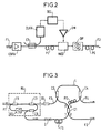
- This document D4 teaches the use of an optical modulator in LiNO 3 to effect the synchronous modulation of the solitons, as shown diagrammatically in FIG. 2.
- the problem with this solution is that the signal rate to be regenerated cannot exceed 20 at 30 Gbit / s (10 Gbit / s in document D4).
- the LiNO 3 modulator is controlled by an electronic control signal generated in a clock circuit from the online soliton signal.
- the clock recovery means comprise an optical coupler C3 for the extraction of a part of the optical signal which propagates between the input F1 and the output F2; a CLKX clock extraction circuit, a delay line to provide an DEL delay, and a GM amplifier to provide the control power necessary to operate the MOD modulator in LiNO 3 .
- Figure 2 shows an optical input amplifier (EDFA) to compensate for the insertion losses of the regeneration circuit; birefringent polarization control devices (PC); and a BP bandpass filter to narrow the spectral distribution of the energy of the solitons.
- EDFA optical input amplifier
- PC birefringent polarization control devices
- BP bandpass filter to narrow the spectral distribution of the energy of the solitons.
- NOLM nonlinear-optical loop mirror
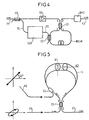
- the NOLM loop consists for example of a two-hole PANDA polarization maintaining fiber.
- fast axis (respectively slow) of the left part becomes the slow axis (respectively fast) of the right part of the loop in figure 5.
- the fiber of the loop (L) is dispersive in polarization, that is, the speed of light propagation at the inside of the fiber is different for a polarization aligned with the fast axis only for polarization orthogonal to the rapid axis of propagation, i.e. the slow axis of the fiber. It is necessary to free yourself of polarization dispersion, which is achieved in using two identical lengths of fiber having a mutually orthogonal arrangement of axes A1, A2 of maintaining polarization, which will have the effect of canceling polarization dispersion.
- D8 L.E. Adams et al., (1994) "All-optical clock recovery using a modelocked figure eight laser with a semiconductor nonlinearity ", electron. lett., v.30, n ° 20, pp. 1696-97, Sep 29, 1994.
- This document teaches the use of a mode blocking laser for all-optical clock recovery.
- a recovery all-optical clock can be used in the device of the invention, and will be described in more detail below with reference to Figure 7.
- the clock signal is recovered from the signal introduced on the input fiber F1 by blocking modes of a ring fiber laser RL, to generate a train of clock pulses at signal bit rate, with reduced jitter due to laser mode blocking.
- the clock pulse train is extracted from the ring laser by the coupler C6, from where it passes via an optical isolator I and a device for mechanical adjustment of the travel time FS before being introduced on input 1 of the coupler C1 of the NOLM.
- the birefringent polarization control devices PC are adjusted to make the NOLM perfectly reflective of a clock signal present on the input 1 of the coupler C1 (reflecting towards the input 1) in the absence of a soliton signal d input on coupler C2.
- a bit "1" of the signal is introduced into the NOLM via the coupler C2, it performs a switching which allows the clock signal to pass, which emerges on the output fiber F2 via the output 2 of the coupler C1, without time jitter.
- the NOLM is therefore used as a controlled switch by the bits of the signal to be regenerated, which switches the signal clock "on” when the signal bit is "1" (the NOLM is transparent to the clock signal) and “off” when the bit of the signal is "0” (NOLM is reflective of the signal clock).
- the time window of the signal bit which constitutes the switching command of the NOLM is enlarged with respect to to the clock signal to ensure insensitivity to the signal jitter to regenerate (see p. 1227 left col., last para. of D5). This is accomplished through the use of a "slip" (or “walk-off” in English) relative between the signal introduced by C2, and the clock signal in direction of co-propagation (that of the needles of a shown in the figure), due to the chromatic dispersion between the two wavelengths used.
- the invention aims to overcome the problems of prior art.
- said device further comprises a first filter to block the wavelength of said clock signal, while allowing said solitons to pass.
- said recovery means are all optical means, without transduction optical / electronic or vice versa.
- said clock recovery means are optoelectronic means, comprising means for optical / electronic transduction and vice versa, as well as electronic amplification and filtering means and means for shaping electronic signals.
- said NOLM includes a 50/50 coupler for signal coupling input-output to the loop of said NOLM.
- the coefficient of coupling of said coupler is chosen with a value asymmetrical, so as to allow adjustment of the relative importance of amplitude modulation and frequency modulation introduced by the NOLM.
- said coupler is a coupler 3x3, i.e. a six-door coupler.
- the signal clock is approximately sinusoidal.
- the device for the invention further comprises at least a first optical amplifier compensating for line losses of the energy of the solitons.
- the device of the invention further comprises at least one second filter, this (these) filter (s) able to filter noise spectral introduced by said (s) at least one optical amplifier (s), and to reduce the width spectral of the solitons while increasing their width temporal, this (these) filter (s) says (s) "filter (s) guiding (s)".
- the device according to the invention further comprises at least a second optical amplifier, able to compensate for losses of energy of the solitons when they cross the said (s) guiding filter (s).
- Figure 1 schematically shows an example of a optical nonlinear mirror (NOLM) known from the prior art, suitable for use in the device of the invention.
- NOLM optical nonlinear mirror
- the NOLM includes a fiber loop optic L; a first optical coupler C1 with its four doors 1, 2, 3, 4, this coupler C1 having a coefficient of coupling which describes the sharing of optical power between the different doors; and a second optical coupler C2 to inject a control signal into the NOLM via the F3 control optical fiber.
- NALM nonlinear amplifier mirror
- the optical signal to be switched by the NOLM is introduced by the input fiber F1 at door 1 of the coupler C1.
- a coupling coefficient of the coupler C1 of 50/50 50% of the power of said optical signal is on door 4, while the other 50% is on door 3 of coupler C1, but with a relative phase shift of ⁇ / 2 radians (90 °) between the of them.
- the two signals therefore propagate in directions opposite in the fiber loop, which will have a length of around 5 to 10 kms. Since the optical paths of the two signals are the same, the signals arrive on the doors 3, 4 respectively of the coupler C1, where they interfere.
- the effective refractive index of the loop L seen by copropagation waves is different from that seen by the waves in counter-propagation. Their speeds of spread are therefore different. Their arrival times on the coupler C1 are different, so these waves do little or no interference. The full power almost optical is on door 2 of color C1, carried on the output optical fiber F2.
- the presence of a control signal on the control fiber F3 is capable of controlling the switching of the nonlinear optical mirror, which will be transparent in presence of the control signal, and which will be reflective the absence of a control signal.
- Switching can be very fast, around 100 GHz at least.
- insertion of a birefringent element in the NOLM loop can invert the switching characteristics, to make the transparent mirror in the absence of the control signal, and reflecting in the presence of a control signal, such as recalled in the introduction to document D6, which deals with problems of sensitivity to the polarization of the signals in the nonlinear operating regime of such device.
- the NOLM that we have just described conforms to that used in the device of Figure 3, already described, which schematically shows a device for soliton regeneration by switching using a NOLM of a clock signal, known from the prior art by the document D5.
- the invention provides a device for online regeneration of optical signals of the soliton type, by the synchronous modulation of the solitons to using a NOLM as shown schematically on the figure 4.
- NOLM is mainly used as a fast optical switch
- the invention proposes to use it as a modulator amplitude.
- the optical signal of the soliton type to be regenerated arrives via the input optical fiber F1, where an optical coupler C3 takes part of the signal to extract a clock signal from it by the recovery means. CLK clock. Then, these means CLK apply said optical clock signal to the control input of the NOLM via the coupler C2.
- the soliton signal will always be at the same wavelength ⁇ s .
- the wavelength ⁇ h of the clock signal will preferably be slightly different from that of the soliton signal ⁇ s , to allow blocking filtering of the clock at the output of the device by a BPC bandpass filter whose bandwidth is centered on the wavelength ⁇ s of the soliton.
- an optical amplifier GS can be placed upstream of the NOLM mirror to compensate the line losses suffered by the soliton since the last once it has been amplified or regenerated.
- the operation of the NOLM is similar to what has been described above with reference to Figure 1.
- the solitons arriving at gate 1 of coupler C1 of the NOLM are thus modulated by the clock signal applied to the input of control F3 via the control coupler C2.
- the times of route of the clock and the solitons according to their routes respective must be adjusted as in the device Figure 3, to allow synchronization of these signals when they are circulating in the NOLM.
- the soliton signal is thus modulated by the envelope of the clock signal, which provides modulation amplitude of the solitons. Indeed, the modulation amplitude is considered sufficient to decrease or even eliminate the Gordon-Haus jitter at the exit of the regeneration.
- the signal soliton is the mirror control signal NOLM, however this signal will have an arbitrary polarization, unknown, and unmanageable.
- the sensitivity of the NOLM to signal polarization can therefore adversely affect the performance of this device of the prior art.
- CLK clock recovery means can be either all optical means (see Figure 7), or optoelectronic means (see Figure 6).
- Figure 6 schematically shows an example of a optoelectronic clock recovery device of a optical signal according to principles known to man of art.
- the optical signal picked up by the coupler sample C3 of figure 4 spreads on the fiber F4 optics up to a PD photodetector which converts the optical signal into electronic signal.
- the signal electronics thus obtained is first amplified by the AE1 microwave electronic amplifier, then in the case of a NRZ signal (non return to zero in English), the signal will be filtered by a first bandpass filter B / 2.
- a NRZ signal non return to zero in English
- the signal will be filtered by a first bandpass filter B / 2.
- the filtered signal is then multiplied in frequency by a frequency doubler X2, and undergoes a second filtering bandpass in filter B.
- filtering by filter B will be the first filtering.
- the signal is then amplified to command a LD laser diode, which emits a light signal at the rate of electronic pulses which are the results of signals optics taken from C3.
- This optical signal can possibly be amplified by an optical amplifier AO1 before being applied to the NOLM command input via the control fiber F3 and the coupler C2 in FIG. 4.
- Figure 7 schematically shows an example of a all-optical clock recovery device of a optical signal according to known principles for blocking modes of a ring fiber laser.
- the optical signal from soliton type, sampled by the C3 coupler FIG. 4 propagates over the optical fiber F4 up to a fiber loop R to which it is coupled via the coupler C7.
- the ring laser includes optical amplification means AOL, an optical isolator I for operation unidirectional, centered optical filtering means FL on the wavelength of the laser light, and means of CONL nonlinear optical coupling to obtain amplitude and / or phase non-linearities as a function of the amplitude of the electric field of light flowing in fiber R.
- These nonlinear means CONL can be by example a NOLM as described in the previous figures or in document D8.
- the ring laser can operate continuously (CW) in the absence of a soliton signal injected via the C7 coupler. However, as soon as a bit stream is introduced via the coupler C7, there is an asymmetric non-linear phase shift introduced between counterpropagating components, increased transmittance of NOLM, and blockage of ring laser modes to the rhythm of the signal bits. These pulses can then be taken via the coupler C8 optics to give a clock signal with substantially no temporal jitter. To make this signal easily usable for synchronous modulation, Figure 7 shows a second AOH optical amplifier and means compression and / or expansion, to give the desired shape pulses from the ring laser (amplitude, duration, temporal form of ascent and descent, ). Indeed, the raw pulses are relatively narrow, and it can it is advisable to widen them before using them. So the clock pulses supplied on the fiber F3 optics will be optimized for the intended use.
- Figure 8 schematically shows a system of transmission of soliton signals according to the invention, comprising a regeneration device according to the invention (C3, CLK, C2, C1, NOLM) as well as a plurality line optical amplifiers (G1, G2, G3 ...) and a plurality of guiding filters (BP1, BP2, BP3 .).
- the guiding filters compress the spectral width of solitons, but remove energy from the solitons by making. This is why the gain of online amplifiers must be greater than the line losses suffered by solitons on the optical fibers (LF1, LF2, ...) between the amplifiers (G1, G2, G3, ).
- the guiding filters compress the spectral width of solitons, but remove energy from the solitons by making. This is why the gain of online amplifiers must be greater than the line losses suffered by solitons on the optical fibers (LF1, LF2, ...) between the amplifiers (G1, G2, G3, ).
- Figure 9 schematically shows an example of a optical nonlinear mirror (NOLM) known from the prior art, with a 3x3 C11 optical coupler at its main input, this NOLM being able to be used in the device the invention.
- NOLM optical nonlinear mirror
- the degradation of the extinction ratio in consequence of the average pumping power (or the rate of filling of the loop by clock signals) seen by counterpropagating signals can be eliminated by this phase shift, if the different parameters are chosen wisely.
- the six-door 3x3 coupler including three doors P1, P2, P3. What matters to us is the relationship phase between the different doors.
- a 2x2 coupler there is a phase shift between the direct path (1,3) and the cross path (1,4) of ⁇ / 2.
- a 3x3 coupler there is a phase shift of ⁇ ⁇ / 3 between the neighboring doors.
- the sign of phase shift it is possible to choose the sign of phase shift to introduce a non-symmetrical phase shift in the NOLM loop. Degradation of extinction ratio as a consequence of the average pumping power (or the loop filling rate by clock signals) seen by counterpropagating signals can be eliminated by this phase shift.
- the soliton signal is injected on the fiber optic F11 via gate P1 of coupler C11.
- the fiber F12, connected to door P2, is not connected (but only finished to avoid stray reflections possible).
- the signals introduced on the F11 fiber are coupled to the other two fibers F12 and F13 within the 3x3 C11 coupler.
- the NOLM works as in the examples precedents.
- the phase shift effects on the waves in counterpropagation can cancel out with the constant asymmetric introduced by the phase shift of ⁇ / 3.
- soliton signal regenerated by synchronous modulation will be presented on the fiber F13 via gate P3 of coupler C11 when the signal is applied to the NOLM on the F3 fiber via the optical coupler C2.
- the device of the invention has been described by making reference to only a few examples of achievements using such and such devices of the known art for constitute the NOLM, to recover and provide the signal clock on the controlled input of the NOLM, and to resolve some minor problems that may be encountered during of the realization of an online regeneration system of solitons.
- the list of embodiments according to the invention is not of course not exhaustive, and those skilled in the art will be able to adapt the device of the invention to its own needs.
Description
L'invention concerne le domaine de télécommunications sur fibre optique, et plus particulièrement des télécommunications sur des longues distances. Il est connu, pour des liaisons très longues distances à fibre optique, d'utiliser un signal de type dit "soliton" ayant des propriétés spectrales particulières qui permettent au signal de se propager sur la fibre dispersive sans dispersion chromatique appréciable, c'est-à-dire que l'on utilise la dépendance de l'indice de réfraction sur l'intensité du signal pour contrebalancer la dispersion chromatique ou vice-versa. La forme spectrale du signal est préservée malgré les effets de la distance de propagation, qui se résument ainsi principalement à des pertes de ligne. Ces pertes de ligne peuvent être compensées par une amplification optique en ligne, par exemple à l'aide d'un amplificateur à fibre dopée Erbium, ou "EDFA" en anglais.The invention relates to the field of telecommunications on optical fiber, and more particularly telecommunications over long distances. He is known, for very long distance fiber optic links, to use a signal of type called "soliton" having special spectral properties that allow the signal to propagate on the dispersive fiber without dispersion appreciable chromatic, that is to say that we use the dependence of the refractive index on the intensity of the signal to counterbalance chromatic dispersion or vice versa. Signal spectral shape is preserved despite the effects of the propagation distance, which thus mainly boil down to line losses. These line losses can be compensated by a online optical amplification, for example using a Erbium doped fiber amplifier, or "EDFA" in English.
Pour la transmission par solitons avec amplification
en ligne (EDFA) les problèmes qui restent à résoudre sont
connus :
Différentes solutions ont été proposées et décrites
dans les documents suivants qui sont expressément incorporés
à la présente demande en tant que descriptions de l'art
antérieur :
Ce document D4 enseigne l'utilisation d'un modulateur optique en LiNO3 pour effectuer la modulation synchrone des solitons, tel que montré schématiquement sur la figure 2. Le problème avec cette solution est que le débit de signaux à régénérer ne pourra dépasser les 20 à 30 Gbit/s (10 Gbit/s dans le document D4). Le modulateur en LiNO3 est commandé par un signal électronique de commande généré dans un circuit d'horloge à partir du signal de solitons en ligne. Les moyens de récupération d'horloge comprennent un coupleur optique C3 pour l'extraction d'une partie du signal optique qui se propage entre l'entrée F1 et la sortie F2 ; un circuit d'extraction d'horloge CLKX, une ligne à retard pour fournir un délai DEL, et un amplificateur GM pour fournir la puissance de commande nécessaire pour faire fonctionner le modulateur MOD en LiNO3. Accessoirement, la figure,2 montre un amplificateur optique d'entrée (EDFA) pour pallier les pertes d'insertion du circuit de régénération ; des dispositifs de contrôle de polarisation (PC) biréfringents ; et un filtre passe-bande BP pour resserrer la distribution spectrale de l'énergie des solitons. Certains de ces accessoires se retrouveront dans des réalisations préférées de l'invention décrites ci-après.This document D4 teaches the use of an optical modulator in LiNO 3 to effect the synchronous modulation of the solitons, as shown diagrammatically in FIG. 2. The problem with this solution is that the signal rate to be regenerated cannot exceed 20 at 30 Gbit / s (10 Gbit / s in document D4). The LiNO 3 modulator is controlled by an electronic control signal generated in a clock circuit from the online soliton signal. The clock recovery means comprise an optical coupler C3 for the extraction of a part of the optical signal which propagates between the input F1 and the output F2; a CLKX clock extraction circuit, a delay line to provide an DEL delay, and a GM amplifier to provide the control power necessary to operate the MOD modulator in LiNO 3 . Incidentally, Figure 2 shows an optical input amplifier (EDFA) to compensate for the insertion losses of the regeneration circuit; birefringent polarization control devices (PC); and a BP bandpass filter to narrow the spectral distribution of the energy of the solitons. Some of these accessories will be found in preferred embodiments of the invention described below.
Par ailleurs, il est connu un système de régénération d'un signal optique ayant la forme d'un train de bits constitué d'impulsions de lumière pour les bits "1" et d'absences d'impulsions pour les bits "0" aux moments prédéterminés et connus par une horloge : D5= J. K. Lucek et K. Smith, (1993) "All optical signal regenerator", Opt. Lett. v.18, n°15, pp.1226-1228, 1 aug.1993) . Le système de ce document D5 est montré sur la figure 3 et décrit ci-après. Furthermore, a regeneration system is known. an optical signal in the form of a bit stream consisting of light pulses for bits "1" and no pulses for "0" bits at times predetermined and known by a clock: D5 = J. K. Lucek and K. Smith, (1993) "All optical signal regenerator", Opt. Lett. v. 18, no. 15, pp. 1226-1228, 1 aug. 1993). The system of this document D5 is shown in Figure 3 and describes below.
D'autres documents sont utiles pour une meilleure compréhension de la présente invention, et seront introduits brièvement avec une appréciation de leurs apports dans ce but. Ces documents sont également expressément incorporés à la présente demande en tant que descriptions de l'art antérieur :Other documents are useful for better understanding of the present invention, and will be introduced briefly with an appreciation of their contributions in this goal. These documents are also expressly incorporated into this application as descriptions of art previous:
D6= N. Finlayson et al., (1992) "Switch inversion and polarization sensitivity of the nonlinear-optical loop mirror (NOLM)", Optics Lett., v.17, n°2, pp. 112-114, 15 jan. 1992. Ce document enseigne que le NOLM peut être configuré comme un,commutateur qui n'est pas ou peu sensible à la polarisation du signal lumineux à commuter dans son régime linéaire, et que la biréfringence de la boucle peut contribuer aux instabilités constatées dans des lasers en anneau à blocage de modes.D6 = N. Finlayson et al., (1992) "Switch inversion and polarization sensitivity of the nonlinear-optical loop mirror (NOLM) ", Optics Lett., v.17, n ° 2, pp. 112-114, 15 Jan. 1992. This document teaches that the NOLM can be configured as a switch that is not or not very sensitive to the polarization of the light signal to be switched in its linear regime, and that the birefringence of the loop can contribute to the instabilities observed in lasers in mode lock ring.
D7= K. Uchiyama et al., (1992) "Ultrafast polarisation - independent all-optical switching using a polarisation diversity scheme in the nonlinear optical loop mirror (NOLM)", electron. lett., v.28, no.20, pp. 1864-1866, 24 sept. 1992. Ce document montre l'utilisation d'un NOLM comme un commutateur, qui est rendu insensible à la polarisation de la lumière du signal à commuter. Ceci est obtenu en utilisant une fibre à maintien de polarisation, que l'on aurait coupée et tournée à 90° au point médian de la boucle du NOLM. Le principe en est illustré en figure 5.D7 = K. Uchiyama et al., (1992) "Ultrafast polarization - independent all-optical switching using a polarization diversity scheme in the nonlinear optical loop mirror (NOLM) ", electron. Lett., V.28, no.20, pp. 1864-1866, 24 Sep 1992. This document demonstrates the use of a NOLM like a switch, which is made insensitive to the polarization of the signal light to be switched. this is obtained using a polarization maintaining fiber, that we would have cut and turned 90 ° at the midpoint of the NOLM loop. The principle is illustrated in Figure 5.
La boucle du NOLM est constituée par exemple d'une fibre à maintien de polarisation PANDA à deux trous. En effectuant une rotation de 90° entre l'axe A1 et l'axe A2 à mi-chemin de propagation, l'axe rapide (respectivement lent) de la partie gauche devient l'axe lent (respectivement rapide) de la partie droite de la boucle sur la figure 5. La fibre de la boucle (L) est dispersive en polarisation, c'est-à-dire que la vitesse de propagation de la lumière à l'intérieur de la fibre est différente pour une polarisation alignée avec l'axe rapide que pour une polarisation orthogonale à l'axe rapide de propagation, c'est-à-dire l'axe lent de la fibre. Il est nécessaire de s'affranchir de la dispersion en polarisation, ce que l'on réalise en utilisant deux longueurs identiques de fibre ayant une disposition mutuellement orthogonale des axes A1, A2 de maintien de polarisation, ce qui aura pour effet d'annuler la dispersion de polarisation.The NOLM loop consists for example of a two-hole PANDA polarization maintaining fiber. In performing a 90 ° rotation between the A1 axis and the A2 axis at propagation halfway, fast axis (respectively slow) of the left part becomes the slow axis (respectively fast) of the right part of the loop in figure 5. The fiber of the loop (L) is dispersive in polarization, that is, the speed of light propagation at the inside of the fiber is different for a polarization aligned with the fast axis only for polarization orthogonal to the rapid axis of propagation, i.e. the slow axis of the fiber. It is necessary to free yourself of polarization dispersion, which is achieved in using two identical lengths of fiber having a mutually orthogonal arrangement of axes A1, A2 of maintaining polarization, which will have the effect of canceling polarization dispersion.
Pour rendre le système indépendant de la polarisation du signal commuté, la polarisation du signal de contrôle qui est introduit dans la boucle L par le coupleur C2 sur la fibre d'entrée de contrôle F3 est injecté à 45° des deux axes orthogonaux A1, A2. De la même manière que précédemment, les effets de la dispersion de polarisation s'annulent.To make the system independent of polarization of the switched signal, the polarization of the control signal which is introduced into the loop L by the coupler C2 on the F3 control input fiber is injected at 45 ° from both orthogonal axes A1, A2. The same way as previously, the effects of polarization dispersion cancel.
D8= L.E. Adams et al., (1994) "All-optical clock recovery using a modelocked figure eight laser with a semiconductor nonlinearity", electron. lett., v.30, n°20, pp. 1696-97, 29 sept. 1994. Ce document enseigne l'utilisation d'un laser à blocage de modes pour la récupération toute-optique d'horloge. Une récupération d'horloge toute-optique peut être utilisée dans le dispositif de l'invention, et sera décrite plus en détail ci-après avec référence à la figure 7.D8 = L.E. Adams et al., (1994) "All-optical clock recovery using a modelocked figure eight laser with a semiconductor nonlinearity ", electron. lett., v.30, n ° 20, pp. 1696-97, Sep 29, 1994. This document teaches the use of a mode blocking laser for all-optical clock recovery. A recovery all-optical clock can be used in the device of the invention, and will be described in more detail below with reference to Figure 7.
D9= D. Sandel et al., (1994) : "Polarisation-independent regenerator with nonlinear optoelectronic phase-locked loop", optical fiber conference proceedings 1994, paper FG2. Ce document fait état d'une utilisation d'un NOLM ayant un coupleur 3x3 à son entrée principale. Dans une réalisation de l'invention, un tel coupleur 3x3 est utilisé pour obtenir une certaine relation de phase, telle qu'enseignée dans ce document. En effet, l'utilisation d'un coupleur 3x3, au lieu d'un coupleur 2x2, introduit un déphasage non symétrique dans la boucle du NOLM. La dégradation de rapport d'extinction en conséquence de la puissance moyen de pompage (ou le taux de remplissage de la boucle par des signaux d'horloge) vue par les signaux en contrepropagation peut être éliminée par ce déphasage, si les différents paramètres sont choisis judicieusement.D9 = D. Sandel et al., (1994): "Polarization-independent regenerator with nonlinear optoelectronic phase-locked loop ", optical fiber conference proceedings 1994, paper FG2. This document describes the use of a NOLM having a 3x3 coupler at its main input. In an embodiment of the invention, such a 3x3 coupler is used to get a certain phase relation, such as taught in this document. Indeed, the use of a 3x3 coupler, instead of a 2x2 coupler, introduces a non-symmetrical phase shift in the NOLM loop. The degradation of extinction ratio as a result of the average pumping power (or the filling rate of the loop by clock signals) seen by the signals in counterpropagation can be eliminated by this phase shift, if the different parameters are carefully chosen.
Le système connu de D5 et montré sur la figure 3 utilise un miroir optique non linéaire (NOLM) pour moduler un signal d'horloge à une première longueur d'onde λh = 1.56µm par le train de bits d'un signal à régénérer, ce signal étant à une deuxième longueur d'onde λs = 1.54µm. Le signal d'horloge ainsi modulé constitue alors le signal régénéré, qui a donc changé de longueur d'onde (1.56 µm en sortie au lieu de 1.54 µm du signal d'entrée).The known system of D5 and shown in FIG. 3 uses a non-linear optical mirror (NOLM) to modulate a clock signal at a first wavelength λ h = 1.56 μm by the bit stream of a signal to be regenerated , this signal being at a second wavelength λ s = 1.54 μm. The clock signal thus modulated then constitutes the regenerated signal, which therefore changed wavelength (1.56 μm at output instead of 1.54 μm from the input signal).
Selon l'enseignement de ce document, le signal
d'horloge est récupéré du signal introduit sur la fibre
d'entrée F1 par blocage de modes d'un laser à fibre en
anneau RL, pour générer un train d'impulsions d'horloge au
rythme des bits du signal, avec une gigue réduite par le
blocage de modes du laser. Le train d'impulsions d'horloge
est extrait du laser en anneau par le coupleur C6, d'où il
transite via un isolateur optique I et un dispositif de
réglage mécanique du temps de trajet FS avant d'être
introduit sur l'entrée 1 du coupleur C1 du NOLM . Le signal
d'entrée à λs = 1.54µm est introduit dans la boucle L du
NOLM par la fibre d'entrée F3 via le coupleur C2. Les
dispositifs biréfringents de contrôle de polarisation PC
sont ajustés pour rendre le NOLM parfaitement réfléchissant
d'un signal d'horloge présent sur l'entrée 1 du coupleur C1
(réfléchissant vers l'entrée 1) en l'absence d'un signal
soliton d'entrée sur le coupleur C2. En revanche, quand un
bit "1" du signal est introduit dans le NOLM via le coupleur
C2, il effectue une commutation qui laisse passer le signal
d'horloge, qui ressort sur la fibre de sortie F2 via la
sortie 2 du coupleur C1, sans gigue temporelle.According to the teaching of this document, the clock signal is recovered from the signal introduced on the input fiber F1 by blocking modes of a ring fiber laser RL, to generate a train of clock pulses at signal bit rate, with reduced jitter due to laser mode blocking. The clock pulse train is extracted from the ring laser by the coupler C6, from where it passes via an optical isolator I and a device for mechanical adjustment of the travel time FS before being introduced on
Le NOLM est donc utilisé comme un commutateur commandé par les bits du signal à régénérer, qui commute le signal d'horloge "on" quand le bit du signal est "1" (le NOLM est transparent au signal d'horloge) et "off" quand le bit du signal est "0" (le NOLM est réfléchissant au signal d'horloge).The NOLM is therefore used as a controlled switch by the bits of the signal to be regenerated, which switches the signal clock "on" when the signal bit is "1" (the NOLM is transparent to the clock signal) and "off" when the bit of the signal is "0" (NOLM is reflective of the signal clock).
La fenêtre temporelle du bit du signal qui constitue la commande de commutation du NOLM est élargie par rapport au signal d'horloge pour assurer une insensibilité à la gigue du signal à régénérer (voir p. 1227 col. de gauche, dernier para. du D5). Ceci est accompli par l'utilisation d'un "glissement" (or "walk-off" en anglais) relatif entre le signal introduit par C2, et le signal d'horloge en direction de co-propagation (celle des aiguilles d'une montre sur la figure), du à la dispersion chromatique entre les deux longueurs d'onde utilisées.The time window of the signal bit which constitutes the switching command of the NOLM is enlarged with respect to to the clock signal to ensure insensitivity to the signal jitter to regenerate (see p. 1227 left col., last para. of D5). This is accomplished through the use of a "slip" (or "walk-off" in English) relative between the signal introduced by C2, and the clock signal in direction of co-propagation (that of the needles of a shown in the figure), due to the chromatic dispersion between the two wavelengths used.
Le système propose par Lucek et Smith n'est pas
approprié pour la régénération de solitons pour plusieurs
raisons :
Les dispositifs de "contrôle de polarisation" (réf. PC
sur la fig. 1 de D5) sont ajustés pour refléter le signal
d'horloge sur la porte 1 en l'absence du bit "1" du signal
(voir D5 p.1227 col. g. dernier para. ) ; mais ce réglage
est à surveiller car dépendant sur des paramètres
d'environnement (température, vibrations, ...)."Polarization control" devices (ref. PC
in fig. 1 of D5) are adjusted to reflect the signal
clock on
La fiabilité d'opération d'un tel dispositif sur le terrain semblerait être loin d'être suffisant par rapport à ces problèmes.The reliability of operation of such a device on the ground would seem to be far from enough compared to these problems.
Le document 'ALL-OPTICAL REGENERATOR BASED ON NONLINEAR FIBRE SAGNAC INTERFEROMETER', JINNO M ET AL, ELECTRONICS LETTERS, vol. 28, no. 14, 2 Juillet 1992 pages 1350-1352 divulgue un dispositif de régénération d'un signal optique de solitons par des moyens de modulation.The document 'ALL-OPTICAL REGENERATOR BASED ON NONLINEAR FIBER SAGNAC INTERFEROMETER ', JINNO M ET AL, ELECTRONICS LETTERS, vol. 28, no. July 14, 2 1992 pages 1350-1352 discloses a device for regenerating an optical signal of solitons by means of modulation.
Le document '80GBIT/S SOLITON DATA TRANSMISSION OVER 500KM WITH UNEQUAL AMPLITUDE SOLITONS FOR TIMING CLOCK EXTRACTION', NAKAZAWA M ET AL, ELECTRONICS LETTERS, vol. 30, no. 21, 13 Octobre 1994 page 1777/1778 divulgue un dispositif de demultiplexage comportant des moyens de récupération d'un signal horloge et des moyens de commutation sous forme de NOLM.The document '80GBIT / S SOLITON DATA TRANSMISSION OVER 500KM WITH UNEQUAL AMPLITUDE SOLITONS FOR TIMING CLOCK EXTRACTION ', NAKAZAWA M ET AL, ELECTRONICS LETTERS, vol. 30, no. October 21, 13, 1994 page 1777/1778 discloses a demultiplexing device comprising means for recovering a clock signal and switching means in the form of NOLM.
L'invention a pour but de pallier les problèmes de l'art antérieur.The invention aims to overcome the problems of prior art.
A ces fins, l'invention propose un dispositif de régénération en ligne d'un signal optique de solitons par une modulation synchrone de ces solitons, ledit dispositif comprenant :
- des moyens de récupération d'un signal d'horloge permettant d'extraire le rythme d'horloge des bits du signal à régénérer ;
- des moyens de modulation permettant de moduler l'amplitude des solitons par ledit signal d'horloge ;
- means for recovering a clock signal making it possible to extract the clock rate from the bits of the signal to be regenerated;
- modulation means for modulating the amplitude of the solitons by said clock signal;
Selon une variante, ledit dispositif comprend en outre un premier filtre pour bloquer la longueur d'onde dudit signal d'horloge, tout en laissant passer lesdits solitons. Selon une variante préférée, lesdits moyens de récupération d'horloge sont des moyens tout optiques, sans transduction optique / électronique ou vice-versa. Selon une autre variante, lesdits moyens de récupération d'horloge sont des moyens optoélectroniques, comprenant des moyens de transduction optique / électronique et vice-versa, ainsi que des moyens électroniques d'amplification et de filtrage et des moyens de mise en forme des signaux électroniques.According to a variant, said device further comprises a first filter to block the wavelength of said clock signal, while allowing said solitons to pass. According to a preferred variant, said recovery means are all optical means, without transduction optical / electronic or vice versa. According to another variant, said clock recovery means are optoelectronic means, comprising means for optical / electronic transduction and vice versa, as well as electronic amplification and filtering means and means for shaping electronic signals.
Selon une réalisation particulière, ledit NOLM comprend un coupleur 50/50 pour le couplage des signaux entrée-sortie vers la boucle dudit NOLM.According to a particular embodiment, said NOLM includes a 50/50 coupler for signal coupling input-output to the loop of said NOLM.
Selon une réalisation avantageuse, le coefficient de couplage dudit coupleur est choisi avec une valeur dissymétrique, de manière à permettre un réglage de l'importance relative de la modulation d'amplitude et de la modulation de fréquence introduites par le NOLM. Dans une réalisation particulière, ledit coupleur est un coupleur 3x3, c'est-à-dire un coupleur à six portes. Dans une réalisation particulièrement avantageuse, le signal d'horloge est approximativement sinusoïdal.According to an advantageous embodiment, the coefficient of coupling of said coupler is chosen with a value asymmetrical, so as to allow adjustment of the relative importance of amplitude modulation and frequency modulation introduced by the NOLM. In particular embodiment, said coupler is a coupler 3x3, i.e. a six-door coupler. In particularly advantageous realization, the signal clock is approximately sinusoidal.
Selon une caractéristique, le dispositif de l'invention comprend en outre au moins un premier amplificateur optique compensant des pertes de ligne de l'énergie des solitons. Selon une autre caractéristique, le dispositif de l'invention comprend en outre au moins un deuxième filtre, ce(s) filtre(s) apte(s) à filtrer du bruit spectral introduit par le (s) dit (s) au moins un amplificateur(s) optique(s), et à réduire la largeur spectrale des solitons tout en augmentant leur largeur temporelle, ce(s) filtre(s) dit (s) "filtre (s) guidant (s) ". Selon une autre caractéristique avantageuse, le dispositif selon l'invention comprend en outre au moins un deuxième amplificateur optique, apte(s) à compenser les pertes d'énergie des solitons quand ils traversent le(s)dit(s) filtre (s) guidant (s).According to one characteristic, the device for the invention further comprises at least a first optical amplifier compensating for line losses of the energy of the solitons. According to another characteristic, the device of the invention further comprises at least one second filter, this (these) filter (s) able to filter noise spectral introduced by said (s) at least one optical amplifier (s), and to reduce the width spectral of the solitons while increasing their width temporal, this (these) filter (s) says (s) "filter (s) guiding (s)". According to another advantageous characteristic, the device according to the invention further comprises at least a second optical amplifier, able to compensate for losses of energy of the solitons when they cross the said (s) guiding filter (s).
L'invention sera mieux comprise, avec ses différentes caractéristiques et avantages, à la lumière de la description détaillée qui suit, avec ses dessins annexés, dont :
- la figure 1, qui montre schématiquement un exemple d'un miroir non linéaire optique (NOLM) connu de l'art antérieur, et apte à être utilisé dans le dispositif de l'invention ;
- la figure 2, déjà décrite, qui montre schématiquement un dispositif de modulation synchrone de solitons, connu de l'art antérieur par le document D4 ;
- la figure 3, déjà décrite, qui montre schématiquement un dispositif de régénération de solitons par commutation à l'aide d'un NOLM d'un signal d'horloge, connu de l'art antérieur par le document D5 ;
- la figure 4, qui montre schématiquement un exemple d'une réalisation selon l'invention d'un dispositif de modulation synchrone de solitons dans lequel le modulateur est un NOLM ;
- la figure 5, déjà décrite, qui montre schématiquement un commutateur NOLM insensible à la polarisation du signal à commuter, tel que connu de l'art antérieur par le document D7 ;
- la figure 6, qui montre schématiquement un exemple d'un dispositif de récupération optoélectronique d'horloge d'un signal optique selon des principes connus de l'homme de l'art ;
- la figure 7, qui montre schématiquement un exemple d'un dispositif de récupération tout-optique d'horloge d'un signal optique selon des principes connus de blocage des modes d'un laser à fibre en anneau ;
- la figure 8 qui montre schématiquement un système de transmission de signaux solitons selon l'invention, comprenant un dispositif de régénération selon l'invention ainsi qu'une pluralité d'amplificateurs optiques de ligne et une pluralité de filtres guidants ;
- la figure 9 qui montre schématiquement un exemple d'un miroir non linéaire optique (NOLM) connu de l'art antérieur, avec un coupleur optique 3x3 à son entrée principale, ce NOLM étant apte à être utilisé dans le dispositif de l'invention.
- FIG. 1, which schematically shows an example of an optical non-linear mirror (NOLM) known from the prior art, and suitable for being used in the device of the invention;
- FIG. 2, already described, which schematically shows a device for synchronous modulation of solitons, known from the prior art by document D4;
- FIG. 3, already described, which schematically shows a device for regenerating solitons by switching using a NOLM of a clock signal, known from the prior art by document D5;
- FIG. 4, which schematically shows an example of an embodiment according to the invention of a device for synchronous modulation of solitons in which the modulator is a NOLM;
- FIG. 5, already described, which schematically shows a NOLM switch insensitive to the polarization of the signal to be switched, as known from the prior art by document D7;
- Figure 6, which schematically shows an example of an optoelectronic clock recovery device of an optical signal according to principles known to those skilled in the art;
- FIG. 7, which schematically shows an example of an all-optical clock recovery device for an optical signal according to known principles for blocking the modes of a ring fiber laser;
- FIG. 8 which schematically shows a system for transmitting soliton signals according to the invention, comprising a regeneration device according to the invention as well as a plurality of optical line amplifiers and a plurality of guiding filters;
- FIG. 9 which schematically shows an example of an optical non-linear mirror (NOLM) known from the prior art, with a 3x3 optical coupler at its main input, this NOLM being suitable for use in the device of the invention.
Les dessins sont donnés à titre d'exemples non limitatifs, illustratifs des principes de l'invention et de quelques variantes. Sur toutes les figures, les mêmes repères se réfèrent aux mêmes éléments, et l'échelle n'est pas toujours respectée pour des raisons de clarté.The drawings are given as examples not limiting, illustrative of the principles of the invention and of some variations. In all the figures, the same benchmarks refer to the same elements, and the scale is not not always respected for reasons of clarity.
La figure 1 montre schématiquement un exemple d'un
miroir non linéaire optique (NOLM) connu de l'art antérieur,
apte à être utilisé dans le dispositif de l'invention. De
manière générale, le NOLM comprend une boucle de fibre
optique L ; un premier coupleur optique C1 avec ses quatre
portes 1, 2, 3, 4, ce coupleur C1 ayant un coefficient de
couplage qui décrit le partage de puissance optique entre
les différentes portes ; et un deuxième coupleur optique C2
pour injecter un signal de contrôle dans le NOLM via la
fibre optique de contrôle F3.Figure 1 schematically shows an example of a
optical nonlinear mirror (NOLM) known from the prior art,
suitable for use in the device of the invention. Of
in general, the NOLM includes a fiber loop
optic L; a first optical coupler C1 with its four
L'adjonction éventuelle d'un amplificateur optique GL dans la boucle peut conférer un gain positif à l'ensemble, ce qui en fait un miror non linéaire amplificateur (NALM), tel que décrit dans le document D1. The possible addition of a GL optical amplifier in the loop can give a positive gain to the whole, which makes it a nonlinear amplifier mirror (NALM), as described in document D1.
Le signal optique à commuter par le NOLM est introduit
par la fibre d'entrée F1 à la porte 1 du coupleur C1.
Décrivons tout d'abord le cas d'un coefficient de couplage
du coupleur C1 de 50/50, en l'absence d'un signal de
contrôle sur la fibre F3. Dans ce cas, 50 % de la puissance
dudit signal optique se trouve sur la porte 4, tandis que
l'autre 50 % se trouve sur la porte 3 du coupleur C1, mais
avec un déphasage relatif de π/2 radians (90°) entre les
deux. Les deux signaux se propagent donc dans des sens
opposés dans la boucle de fibre, qui aura une longueur de
l'ordre de 5 à 10 kms. Puisque les chemins optiques des deux
signaux sont identiques, les signaux arrivent sur les portes
3, 4 respectivement du coupleur C1, où ils interfèrent.The optical signal to be switched by the NOLM is introduced
by the input fiber F1 at
Puisque les deux signaux sont déphasés de π/2, il y a
interférence destructive pour l'onde résultante dirigée vers
la porte 2 du coupleur C1, donc il n'y a pas de transmission
du signal vers la fibre de sortie F2. En revanche,
l'interférence est constructive pour l'onde résultante
dirigée vers la porte 1 du coupleur C1, donc le signal
présenté sur la porte 1 est totalement réfléchi par le miror
NOLM vers la porte 1 dans ce cas.Since the two signals are phase shifted by π / 2, there are
destructive interference for the resulting wave directed towards
Maintenant considérons le cas où il y a un signal de contrôle présent sur la fibre optique de contrôle F3. Ce signal sera couplé dans la boucle du NOLM par le coupleur optique C2, et se propagera dans la boucle dans le sens des aiguilles d'une montre. Les ondes du signal qui circulent dans la boucle en sens contraire ne seront pas ou très peu affectées par la présence d'un signal de contrôle. En revanche, les ondes du signal qui se propagent dans le même sens dans la boucle seront perturbées. En effet, la fibre de la boucle L présente un effet non linéaire, qui change l'indice de réfraction de la fibre en fonction de la puissance optique, ou plus exactement en fonction de l'amplitude du champ électrique dans la fibre (effet Kerr). Les champs électriques des ondes circulant ensemble, dites "en copropagation", se superposent linéairement, donc l'intensité résultante du champ électrique est plus grande que celle des ondes se propageant dans l'autre sens dans la boucle L.Now consider the case where there is a signal control present on the F3 control optical fiber. This signal will be coupled into the NOLM loop by the coupler C2 optic, and will propagate in the loop in the direction of Clockwise. Signal waves flowing in the loop in the opposite direction will not be or very little affected by the presence of a control signal. In signal waves that propagate in the same sense in the loop will be disturbed. Indeed, the fiber of the loop L has a non-linear effect, which changes the refractive index of the fiber as a function of the optical power, or more exactly depending on the amplitude of the electric field in the fiber (Kerr effect). The electric fields of waves flowing together, say "in copropagation", overlap linearly, therefore the resulting electric field intensity is greater than that of waves propagating in the other direction in the loop L.
L'indice de réfraction effective de la boucle L vue
par les ondes en copropagation est différente de celle vue
par les ondes en contre-propagation. Leurs vitesses de
propagation sont donc différentes. Leurs temps d'arrivée
sur le coupleur C1 sont différents, donc ces ondes
n'interfèrent pas ou peu. La totalité de la puissance
optique ou presque se trouve sur la porte 2 du couleur C1,
véhiculée sur la fibre optique de sortie F2.The effective refractive index of the loop L seen
by copropagation waves is different from that seen
by the waves in counter-propagation. Their speeds of
spread are therefore different. Their arrival times
on the coupler C1 are different, so these waves
do little or no interference. The full power
almost optical is on
Ainsi, la présence d'un signal de contrôle sur la fibre de contrôle F3 est capable de commander la commutation du miroir optique non linéaire, qui sera transparent en présence du signal de contrôle, et qui sera réfléchissant en l'absence d'un signal de contrôle. La commutation peut être très rapide, de l'ordre de 100 GHz au moins. L'insertion d'un élément biréfringent dans la boucle du NOLM peut invertir les caractéristiques de commutation, pour rendre le miroir transparent en l'absence du signal de contrôle, et réfléchissant en présence d'un signal de contrôle, tel que rappelé dans l'introduction du document D6, qui traite des problèmes de sensitivité à la polarisation des signaux dans le régime non linéaire de fonctionnement d'un tel dispositif.Thus, the presence of a control signal on the control fiber F3 is capable of controlling the switching of the nonlinear optical mirror, which will be transparent in presence of the control signal, and which will be reflective the absence of a control signal. Switching can be very fast, around 100 GHz at least. insertion of a birefringent element in the NOLM loop can invert the switching characteristics, to make the transparent mirror in the absence of the control signal, and reflecting in the presence of a control signal, such as recalled in the introduction to document D6, which deals with problems of sensitivity to the polarization of the signals in the nonlinear operating regime of such device.
Le NOLM que nous venons de décrire est conforme à celui utilisé dans le dispositif de la figure 3, déjà décrite, qui montre schématiquement un dispositif de régénération de solitons par commutation à l'aide d'un NOLM d'un signal d'horloge, connu de l'art antérieur par le document D5.The NOLM that we have just described conforms to that used in the device of Figure 3, already described, which schematically shows a device for soliton regeneration by switching using a NOLM of a clock signal, known from the prior art by the document D5.
Pour pallier les inconvénients de l'art antérieur tel que représenté sur les figures 2 et 3, l'invention propose un dispositif de régénération en ligne des signaux optiques de type soliton, par la modulation synchrone des solitons à l'aide d'un NOLM tel que montré schématiquement sur la figure 4. Alors que dans l'art antérieur le NOLM est utilisé principalement comme un commutateur optique rapide, l'invention propose de l'utiliser comme un modulateur d'amplitude.To overcome the drawbacks of the prior art such as shown in Figures 2 and 3, the invention provides a device for online regeneration of optical signals of the soliton type, by the synchronous modulation of the solitons to using a NOLM as shown schematically on the figure 4. Whereas in the prior art the NOLM is mainly used as a fast optical switch, the invention proposes to use it as a modulator amplitude.
Dans le dispositif montré sur la figure 4, le signal optique de type soliton à régénérer arrive par la fibre optique d'entrée F1, où un coupleur optique C3 prélève une partie du signal pour en extraire un signal d'horloge par les moyens de récupération d'horloge CLK. Ensuite, ces moyens CLK appliquent ledit signal optique d'horloge sur l'entrée de contrôle du NOLM via le coupleur C2. Le signal soliton sera toujours à la même longueur d'onde λs. La longueur d'onde λh du signal d'horloge sera de préférence légèrement différente de celle du signal soliton λs, pour permettre le filtrage bloquant de l'horloge en sortie du dispositif par un filtre passe-bande BPC dont la bande passante est centrée sur la longueur d'onde λs du soliton.In the device shown in FIG. 4, the optical signal of the soliton type to be regenerated arrives via the input optical fiber F1, where an optical coupler C3 takes part of the signal to extract a clock signal from it by the recovery means. CLK clock. Then, these means CLK apply said optical clock signal to the control input of the NOLM via the coupler C2. The soliton signal will always be at the same wavelength λ s . The wavelength λ h of the clock signal will preferably be slightly different from that of the soliton signal λ s , to allow blocking filtering of the clock at the output of the device by a BPC bandpass filter whose bandwidth is centered on the wavelength λ s of the soliton.
En aval du coupleur de prélèvement C3, le signal
soliton continue à se propager sur la fibre optique d'entrée
F1 jusqu'à la porte d'entrée 1 du coupleur C1 du NOLM.
Selon une variante de l'invention, un amplificateur optique
GS peut être placé en amont du miroir NOLM pour compenser
les pertes en ligne subies par le soliton depuis la dernière
fois qu'il a été amplifié ou régénéré.Downstream of the C3 sampling coupler, the signal
soliton continues to propagate on the input optical fiber
F1 to the
Le fonctionnement du NOLM est similaire à ce qui a été
décrit ci-dessus en référence à la figure 1. Les solitons
arrivant à la porte 1 du coupleur C1 du NOLM sont ainsi
modulés par le signal d'horloge appliqué à l'entrée de
contrôle F3 via le coupleur de contrôle C2. Les temps de
trajet de l'horloge et des solitons selon leurs trajets
respectifs doivent être ajustés comme dans le dispositif de
la figure 3, pour permettre la synchronisation de ces
signaux quand ils circulent dans le NOLM.The operation of the NOLM is similar to what has been
described above with reference to Figure 1. The solitons
arriving at
Le signal soliton est ainsi modulé par l'enveloppe du signal d'horloge, ce qui permet de procurer une modulation d'amplitude des solitons. En effet, la modulation d'amplitude est jugée suffisante pour diminuer, voire éliminer la gigue Gordon-Haus à la sortie du dispositif de régénération.The soliton signal is thus modulated by the envelope of the clock signal, which provides modulation amplitude of the solitons. Indeed, the modulation amplitude is considered sufficient to decrease or even eliminate the Gordon-Haus jitter at the exit of the regeneration.
Il est préférable d'utiliser une fibre à maintien de polarisation pour la réalisation du NOLM de l'invention, conformément à la figure 5, déjà décrite. On s'arrange pour injecter le signal optique d'horloge dans le NOLM via le coupleur C2 avec son axe de polarisation orienté à 45° par rapport aux axes A1, A2 de maintien dans la fibre de boucle L. Le fonctionnement du dispositif est ainsi insensible à la polarisation du signal soliton à moduler, ce qui constitue un avantage majeur par rapport aux réalisations de l'art antérieur, et en particulier la réalisation de la figure 3. En effet, dans la réalisation de la figure 3, le signal soliton constitue le signal de commande du miroir NOLM, or ce signal aura une polarisation arbitraire, inconnue, et non-maitrisable. La sensibilité du NOLM à la polarisation du signal peut donc nuire aux performances de ce dispositif de l'art antérieur.It is preferable to use a fiber to maintain polarization for the realization of the NOLM of the invention, according to Figure 5, already described. We arrange for inject the optical clock signal into the NOLM via the coupler C2 with its polarization axis oriented at 45 ° by relative to the axes A1, A2 for holding in the loop fiber L. The operation of the device is thus insensitive to the polarization of the soliton signal to be modulated, which constitutes a major advantage compared to the achievements of the prior art, and in particular the realization of the Figure 3. Indeed, in the embodiment of Figure 3, the signal soliton is the mirror control signal NOLM, however this signal will have an arbitrary polarization, unknown, and unmanageable. The sensitivity of the NOLM to signal polarization can therefore adversely affect the performance of this device of the prior art.
Les moyens CLK de récupération d'horloge peuvent être soit des moyens tout optiques (voir figure 7), soit des moyens optoélectroniques (voir figure 6).CLK clock recovery means can be either all optical means (see Figure 7), or optoelectronic means (see Figure 6).
La figure 6 montre schématiquement un exemple d'un dispositif de récupération optoélectronique d'horloge d'un signal optique selon des principes connus de l'homme de l'art. Le signal optique prélevé par le coupleur de prélèvement C3 de la figure 4 se propage sur la fibre optique F4 jusqu'à un photodétecteur PD qui convertit le signal optique en signal électronique. Le signal électronique ainsi obtenu est d'abord amplifié par l'amplificateur électronique hyperfréquence AE1, puis dans le cas d'un signal NRZ (non return to zero en anglais), le signal sera filtré par un premier filtre passe-bande B/2. Dans l'exemple de la figure 6, et pour un signal NRZ le signal filtré est ensuite multiplié en fréquence par un doubleur de fréquence X2, et subit un deuxième filtrage passe-bande dans le filtre B. Dans le cas d'un signal soliton, le filtrage par le filtre B sera le premier filtrage. Le signal est alors amplifié pour commander un laser diode LD, qui émet un signal lumineux au rythme des impulsions électroniques qui sont les résultats des signaux optiques prélevés en C3. Ce signal optique peut éventuellement être amplifié par un amplificateur optique AO1 avant d'être appliqué à l'entrée de commande du NOLM via la fibre de commande F3 et le coupleur C2 de la figure 4.Figure 6 schematically shows an example of a optoelectronic clock recovery device of a optical signal according to principles known to man of art. The optical signal picked up by the coupler sample C3 of figure 4 spreads on the fiber F4 optics up to a PD photodetector which converts the optical signal into electronic signal. The signal electronics thus obtained is first amplified by the AE1 microwave electronic amplifier, then in the case of a NRZ signal (non return to zero in English), the signal will be filtered by a first bandpass filter B / 2. In the example in Figure 6, and for an NRZ signal the filtered signal is then multiplied in frequency by a frequency doubler X2, and undergoes a second filtering bandpass in filter B. In the case of a signal soliton, filtering by filter B will be the first filtering. The signal is then amplified to command a LD laser diode, which emits a light signal at the rate of electronic pulses which are the results of signals optics taken from C3. This optical signal can possibly be amplified by an optical amplifier AO1 before being applied to the NOLM command input via the control fiber F3 and the coupler C2 in FIG. 4.
La figure 7 montre schématiquement un exemple d'un dispositif de récupération tout-optique d'horloge d'un signal optique selon des principes connus de blocage des modes d'un laser à fibre en anneau. Le signal optique de type soliton, prélevé par le coupleur de prélèvement C3 de la figure 4, se propage sur la fibre optique F4 jusqu'à une boucle de fibre R à laquelle il est couplé via le coupleur C7. La boucle de fibre R et les différent composants optiques qui s'y trouvent forment un laser en anneau, tel que déjà décrit en référence à la figure 3 (repère RL) ou tel que décrit dans le document D8 de L. E. Adams et al. Le laser en anneau comprend des moyens d'amplification optique AOL, un isolateur optique I pour un fonctionnement unidirectionnel, des moyens de filtrage optique FL centrés sur la longueur d'onde de la lumière laser, et des moyens de couplage optique non linéaire CONL permettant d'obtenir des non linéarités d'amplitude et/ou de phase en fonction de l'amplitude du champ électrique de la lumière circulant dans la fibre R. Ces moyens non linéaires CONL peuvent être par exemple un NOLM tel que décrit sur les figures précédentes ou dans le document D8.Figure 7 schematically shows an example of a all-optical clock recovery device of a optical signal according to known principles for blocking modes of a ring fiber laser. The optical signal from soliton type, sampled by the C3 coupler FIG. 4 propagates over the optical fiber F4 up to a fiber loop R to which it is coupled via the coupler C7. The R fiber loop and the different components optics there form a ring laser, such that already described with reference to Figure 3 (reference RL) or as described in document D8 by L. E. Adams et al. The ring laser includes optical amplification means AOL, an optical isolator I for operation unidirectional, centered optical filtering means FL on the wavelength of the laser light, and means of CONL nonlinear optical coupling to obtain amplitude and / or phase non-linearities as a function of the amplitude of the electric field of light flowing in fiber R. These nonlinear means CONL can be by example a NOLM as described in the previous figures or in document D8.
Le laser en anneau peut fonctionner en continu (CW) en l'absence d'un signal soliton injecté via le coupleur C7. En revanche, dès qu'un train de bits est introduit via le coupleur C7, il y a un déphasage non linéaire asymétrique introduit entre des composants en contrepropagation, augmentation de la transmitivité du NOLM, et blocage de modes du laser en anneau au rythme des bits du signal. Ces impulsions peuvent être ensuite prélevées via le coupleur optique C8 pour donner un signal d'horloge sensiblement sans gigue temporelle. Pour rendre ce signal aisément exploitable en vue de la modulation synchrone, la figure 7 montre un deuxième amplificateur optique AOH et des moyens de compression et/ou expansion, pour donner la forme voulue aux impulsions issues du laser en anneau (amplitude, durée, forme temporelle de montée et descente,...). En effet, les impulsions brutes sont relativement étroites, et il peut être souhaitable de les élargir avant de les utiliser. Ainsi, les impulsions d'horloge fournies sur la fibre optique F3 seront optimisées pour l'utilisation voulue.The ring laser can operate continuously (CW) in the absence of a soliton signal injected via the C7 coupler. However, as soon as a bit stream is introduced via the coupler C7, there is an asymmetric non-linear phase shift introduced between counterpropagating components, increased transmittance of NOLM, and blockage of ring laser modes to the rhythm of the signal bits. These pulses can then be taken via the coupler C8 optics to give a clock signal with substantially no temporal jitter. To make this signal easily usable for synchronous modulation, Figure 7 shows a second AOH optical amplifier and means compression and / or expansion, to give the desired shape pulses from the ring laser (amplitude, duration, temporal form of ascent and descent, ...). Indeed, the raw pulses are relatively narrow, and it can it is advisable to widen them before using them. So the clock pulses supplied on the fiber F3 optics will be optimized for the intended use.
La figure 8 montre schématiquement un système de transmission de signaux solitons selon l'invention, comprenant un dispositif de régénération selon l'invention (C3, CLK, C2, C1, NOLM) ainsi qu'une pluralité d'amplificateurs optiques de ligne (G1, G2, G3...) et une pluralité de filtres guidants (BP1, BP2, BP3....). Les filtres guidants compriment la largeur spectrale des solitons, mais enlèvent de l'énergie des solitons en se faisant. C'est pourquoi le gain des amplificateurs en ligne doit être supérieur aux pertes de ligne subies par les solitons sur les fibres optiques (LF1, LF2, ...) entre les amplificateurs (G1, G2, G3, ...). En réduisant la largeur spectrale des solitons, la gigue temporelle est aussi réduite par les filtres guidants, tel qu'expliqué dans le document D2.Figure 8 schematically shows a system of transmission of soliton signals according to the invention, comprising a regeneration device according to the invention (C3, CLK, C2, C1, NOLM) as well as a plurality line optical amplifiers (G1, G2, G3 ...) and a plurality of guiding filters (BP1, BP2, BP3 ....). The guiding filters compress the spectral width of solitons, but remove energy from the solitons by making. This is why the gain of online amplifiers must be greater than the line losses suffered by solitons on the optical fibers (LF1, LF2, ...) between the amplifiers (G1, G2, G3, ...). By reducing the width spectral of the solitons, the temporal jitter is also reduced by the guiding filters, as explained in the document D2.
La figure 9 montre schématiquement un exemple d'un miroir non linéaire optique (NOLM) connu de l'art antérieur, avec un coupleur optique 3x3 C11 à son entrée principale, ce NOLM étant apte à être utilisé dans le dispositif de l'invention. L'utilisation d'un coupleur 3x3, au lieu d'un coupleur 2x2, introduit un déphasage non symétrique dans la boucle du NOLM. La dégradation de rapport d'extinction en conséquence de la puissance moyen de pompage (ou le taux de remplissage de la boucle par des signaux d'horloge) vue par les signaux en contrepropagation peut être éliminée par ce déphasage, si les différents paramètres sont choisis judicieusement.Figure 9 schematically shows an example of a optical nonlinear mirror (NOLM) known from the prior art, with a 3x3 C11 optical coupler at its main input, this NOLM being able to be used in the device the invention. The use of a 3x3 coupler, instead of a 2x2 coupler, introduces a non-symmetrical phase shift in the NOLM loop. The degradation of the extinction ratio in consequence of the average pumping power (or the rate of filling of the loop by clock signals) seen by counterpropagating signals can be eliminated by this phase shift, if the different parameters are chosen wisely.
Le coupleur 3x3 à six portes, dont trois portes d'entrée P1, P2, P3. Ce qui nous importe c'est la relation de phase entre les différentes portes. Dans le cas d'un coupleur 2x2, il existe un déphasage entre le chemin direct (1,3) et le chemin croisé (1,4) de π/2. Dans le cas d'un coupleur 3x3, il existe un déphasage de ± π/3 entre les portes voisines. Avec le bon choix des portes d'entrée/sortie, il est possible de choisir le signe du déphasage pour introduire un déphasage non symétrique dans la boucle du NOLM. La dégradation de rapport d'extinction en conséquence de la puissance moyenne de pompage (ou le taux de remplissage de la boucle par des signaux d'horloge) vue par les signaux en contrepropagation peut être éliminée par ce déphasage.The six-door 3x3 coupler, including three doors P1, P2, P3. What matters to us is the relationship phase between the different doors. In the case of a 2x2 coupler, there is a phase shift between the direct path (1,3) and the cross path (1,4) of π / 2. In the case of a 3x3 coupler, there is a phase shift of ± π / 3 between the neighboring doors. With the right choice of doors input / output, it is possible to choose the sign of phase shift to introduce a non-symmetrical phase shift in the NOLM loop. Degradation of extinction ratio as a consequence of the average pumping power (or the loop filling rate by clock signals) seen by counterpropagating signals can be eliminated by this phase shift.
Par exemple, le signal soliton est injecté sur la fibre optique F11 via la porte P1 du coupleur C11. La fibre F12, raccordée à la porte P2, n'est pas connectée (mais seulement terminée pour éviter des réflexions parasites éventuelles). Les signaux introduits sur la fibre F11 sont couplés aux deux autres fibres F12 et F13 au sein du coupleur 3x3 C11. Le NOLM fonctionne comme dans les exemples précédents. Les effets de déphasage sur les ondes en contrepropagation peuvent s'annuler avec la constante asymétrique introduite par le déphasage de π/3.For example, the soliton signal is injected on the fiber optic F11 via gate P1 of coupler C11. The fiber F12, connected to door P2, is not connected (but only finished to avoid stray reflections possible). The signals introduced on the F11 fiber are coupled to the other two fibers F12 and F13 within the 3x3 C11 coupler. The NOLM works as in the examples precedents. The phase shift effects on the waves in counterpropagation can cancel out with the constant asymmetric introduced by the phase shift of π / 3.
Comme dans les cas précédents, le signal soliton régénéré par modulation synchrone sera présenté sur la fibre F13 via la porte P3 du coupleur C11 quand le signal d'horloge est appliqué au NOLM sur la fibre F3 via le coupleur optique C2.As in the previous cases, the soliton signal regenerated by synchronous modulation will be presented on the fiber F13 via gate P3 of coupler C11 when the signal is applied to the NOLM on the F3 fiber via the optical coupler C2.
Le dispositif de l'invention a été décrit en faisant référence à quelques exemples seulement de réalisations utilisant tels ou tels dispositifs de l'art connu pour constituer le NOLM, pour récupérer et fournir le signal d'horloge sur l'entrée commandé du NOLM, et pour résoudre quelques mineurs problèmes que l'on pourra rencontrer lors de la réalisation d'un système de régénération en ligne de solitons. La liste de réalisations selon l'invention n'est bien sur pas exhaustive, et l'homme de l'art saura adapter le dispositif de l'invention à ses propres besoins.The device of the invention has been described by making reference to only a few examples of achievements using such and such devices of the known art for constitute the NOLM, to recover and provide the signal clock on the controlled input of the NOLM, and to resolve some minor problems that may be encountered during of the realization of an online regeneration system of solitons. The list of embodiments according to the invention is not of course not exhaustive, and those skilled in the art will be able to adapt the device of the invention to its own needs.
Claims (11)
- In-line regenerating apparatus for regenerating a soliton optical signal by performing synchronous modulation on the solitons, said apparatus including:clock signal recovery means enabling the clock rate to be extracted from the bits of the signal to be regenerated (C3, CLK); andmodulation means enabling the amplitude of the solitons to be modulated by said clock signal;said modulation means being constituted by a non-linear optical loop mirror (NOLM).
- Apparatus according to claim 1, characterized in that said apparatus further includes a first filter (BPC) for stopping the wavelength λh of said clock signal, while allowing said solitons (λs) to pass therethrough.
- Apparatus according to claim 1 or 2, characterized in that said clock recovery means (C3, CLK) are all-optical means, with no optical-to-electronic or electronic-to-optical transducer means.
- Apparatus according to claim 1 or 2, characterized in that said clock recovery means are opto-electronic means comprising optical-to-electronic transducer means (PD) and electronic-to-optical transducer means (LD), together with electronic amplification means (AE1, AE2) and electronic filtering means (B/2, B), and shaping means (NRZ) for shaping the electronic signals.
- Apparatus according to any one of claims 1 to 4, characterized in that said NOLM includes a 50/50 coupler (C1) for coupling the input-output signals towards the loop (L) of said NOLM.
- Apparatus according to any one of claims 1 to 4, characterized in that said NOLM includes a coupler (C1) having an asymmetrical coupling coefficient, so as to make it possible to adjust the relative size of the amplitude modulation and of the frequency modulation that are imparted by said NOLM.
- Apparatus according to any one of claims 1 to 4, characterized in that said NOLM includes a coupler (C11) and said coupler (C11) is a 3x3 coupler.
- Apparatus according to any one of claims 1 to 7, characterized in that said clock signal is approximately in the form of a sine-wave.
- Apparatus according to any one of claims 1 to 8, characterized in that said apparatus of the invention further includes at least one first optical amplifier (GS) compensating for the line losses of energy from the solitons.
- Apparatus according to claim 9, characterized in that said apparatus of the invention further includes at least one "guiding" second filter (BP1, ...) capable of filtering out spectrum noise imparted by said at least one optical amplifier (GS, ...), and of reducing the spectrum width of the solitons while increasing their time width.
- Apparatus according to claim 10, characterized in that said apparatus of the invention further includes at least one second optical amplifier (G1, ...), capable of compensating for energy losses from the solitons when they pass through said guiding filter(s) (BP1, ...).
Applications Claiming Priority (2)
| Application Number | Priority Date | Filing Date | Title |
|---|---|---|---|
| FR9415555A FR2728746B1 (en) | 1994-12-23 | 1994-12-23 | DEVICE FOR THE ON-LINE REGENERATION OF A SIGNAL TRANSMITTED BY SOLITONS VIA THE SYNCHRONOUS MODULATION OF THE SOLITONS USING A NON-LINEAR OPTICAL MIRROR |
| FR9415555 | 1994-12-23 |
Publications (2)
| Publication Number | Publication Date |
|---|---|
| EP0718992A1 EP0718992A1 (en) | 1996-06-26 |
| EP0718992B1 true EP0718992B1 (en) | 2004-06-16 |
Family
ID=9470173
Family Applications (1)
| Application Number | Title | Priority Date | Filing Date |
|---|---|---|---|
| EP95402857A Expired - Lifetime EP0718992B1 (en) | 1994-12-23 | 1995-12-18 | Inline regenerator device of a soliton signal via synchronous solitory modulation using a non-linear optical mirror |
Country Status (7)
| Country | Link |
|---|---|
| US (1) | US5757529A (en) |
| EP (1) | EP0718992B1 (en) |
| JP (1) | JP3766462B2 (en) |
| AU (1) | AU709890B2 (en) |
| CA (1) | CA2165611C (en) |
| DE (1) | DE69533157T2 (en) |
| FR (1) | FR2728746B1 (en) |
Families Citing this family (26)
| Publication number | Priority date | Publication date | Assignee | Title |
|---|---|---|---|---|
| FR2742887B1 (en) * | 1995-12-21 | 1998-01-16 | Alcatel Submarcom | ADJUSTABLE OPTICAL MODULATOR OF AMPLITUDE AND PHASE, AND SOLITON REGENERATOR INCLUDING SUCH A MODULATOR |
| JP3036424B2 (en) * | 1996-01-12 | 2000-04-24 | 日本電気株式会社 | Optical repeater with signal regeneration function |
| FR2744246B1 (en) * | 1996-01-30 | 1998-03-13 | Alcatel Nv | POLARIZATION-INDEPENDENT KERR MODULATOR, AND ANY CLOCK OPTICAL RECOVERY DEVICE INCLUDING SUCH A MODULATOR |
| DE19640070A1 (en) * | 1996-09-28 | 1998-04-02 | Alsthom Cge Alcatel | Wavelength converter that is suitable for high bit repetition frequencies |
| GB2320635A (en) * | 1996-12-19 | 1998-06-24 | Northern Telecom Ltd | Optical timing detection using an interferometer |
| FR2758192B1 (en) * | 1997-01-06 | 1999-02-05 | Alsthom Cge Alcatel | HIGH-THROUGHPUT SOLITON REGENERATOR |
| FR2759832B1 (en) * | 1997-02-18 | 1999-03-26 | Alsthom Cge Alcatel | OPTICAL REGENERATION FOR WAVELENGTH MULTIPLEXED SOLITON SIGNAL FIBER OPTIC TRANSMISSION SYSTEMS |
| FR2759830B1 (en) * | 1997-02-18 | 1999-03-26 | Alsthom Cge Alcatel | OPTICAL REGENERATION FOR NON-SOLITON SIGNAL FIBER OPTIC TRANSMISSION SYSTEMS |
| FR2761169B1 (en) * | 1997-03-20 | 1999-04-30 | Alsthom Cge Alcatel | OPTICALLY MODULATED REGENERATOR FOR SOLITON SIGNAL FIBER OPTIC TRANSMISSION SYSTEMS |
| FR2763144B1 (en) * | 1997-05-07 | 1999-07-23 | Alsthom Cge Alcatel | REGENERATION DEVICE AND METHOD FOR SOLITON TRAINING |
| US5970188A (en) * | 1997-06-20 | 1999-10-19 | Sprint Communications Company L.P. | Method and apparatus for controlling an optical signal |
| DE19737482A1 (en) * | 1997-08-28 | 1999-03-04 | Alsthom Cge Alcatel | Process for optical transmission over an optical fiber network, and optical transmission network |
| EP1076842A4 (en) | 1998-05-08 | 2004-08-11 | Univ Michigan | Soliton pulse transmission over waveguide fiber lengths |
| FR2779297B1 (en) * | 1998-05-28 | 2000-09-08 | Alsthom Cge Alcatel | DOUBLE FILTERING SOLITON SIGNAL FIBER OPTIC TRANSMISSION SYSTEM |
| US20020075536A1 (en) * | 1998-06-30 | 2002-06-20 | Xiang-Dong Cao | Multi-wavelength all-optical regenerators ( mars) |
| US6141132A (en) * | 1999-02-02 | 2000-10-31 | Silkroad, Inc. | Method of modulating a coherent light source with an electronic digital data stream |
| US6529876B1 (en) * | 1999-03-26 | 2003-03-04 | Stephen H. Dart | Electronic template medical records coding system |
| US6721512B1 (en) * | 2000-03-02 | 2004-04-13 | Nortel Networks Limited | High speed jitter correction and adaptive chromatic dispersion compensation in optical dispersion compensation in optical systems using RZ format |
| US6580857B1 (en) | 2000-04-19 | 2003-06-17 | Nortel Networks Limited | Apparatus for reshaping optical pulses |
| GB2371160B (en) * | 2001-01-10 | 2004-06-30 | Univ Aston | Optical pulse regenerating transmission lines |
| US6701049B1 (en) * | 2002-03-22 | 2004-03-02 | The United States Of America As Represented By The National Security Agency | Optical clock recovery device using non-linear optical waveguides |
| US7085496B2 (en) * | 2002-05-30 | 2006-08-01 | Fujitsu Limited | Passive add/drop amplifier for optical networks and method |
| US7075712B2 (en) * | 2002-05-30 | 2006-07-11 | Fujitsu Limited | Combining and distributing amplifiers for optical network and method |
| US7333686B1 (en) * | 2002-12-10 | 2008-02-19 | Avanex Corporation | System and method for a re-configurable optical channel dropping de-multiplexer |
| KR100601046B1 (en) * | 2003-12-24 | 2006-07-14 | 한국전자통신연구원 | System for all-optical clock recovery |
| US7620274B2 (en) * | 2007-02-12 | 2009-11-17 | Bti Systems Inc. | Optical protection switch and method for optical protection switching |
Family Cites Families (4)
| Publication number | Priority date | Publication date | Assignee | Title |
|---|---|---|---|---|
| US4309267A (en) * | 1980-07-21 | 1982-01-05 | Bell Telephone Laboratories, Incorporated | Reactive sputter etching apparatus |
| EP0567693A1 (en) * | 1992-04-27 | 1993-11-03 | BRITISH TELECOMMUNICATIONS public limited company | Optical clock recovery |
| US5369520A (en) * | 1992-05-22 | 1994-11-29 | At&T Corp. | Optical regeneration circuit |
| US5309267A (en) * | 1992-09-25 | 1994-05-03 | At&T Bell Laboratories | Optical communication system using a Sagnac switch |
-
1994
- 1994-12-23 FR FR9415555A patent/FR2728746B1/en not_active Expired - Fee Related
-
1995
- 1995-12-12 US US08/570,858 patent/US5757529A/en not_active Expired - Fee Related
- 1995-12-18 DE DE69533157T patent/DE69533157T2/en not_active Expired - Fee Related
- 1995-12-18 EP EP95402857A patent/EP0718992B1/en not_active Expired - Lifetime
- 1995-12-19 CA CA002165611A patent/CA2165611C/en not_active Expired - Fee Related
- 1995-12-20 AU AU40545/95A patent/AU709890B2/en not_active Ceased
- 1995-12-22 JP JP33500295A patent/JP3766462B2/en not_active Expired - Fee Related
Also Published As
| Publication number | Publication date |
|---|---|
| AU4054595A (en) | 1996-07-04 |
| EP0718992A1 (en) | 1996-06-26 |
| CA2165611A1 (en) | 1996-06-24 |
| FR2728746A1 (en) | 1996-06-28 |
| JP3766462B2 (en) | 2006-04-12 |
| DE69533157T2 (en) | 2005-08-25 |
| US5757529A (en) | 1998-05-26 |
| DE69533157D1 (en) | 2004-07-22 |
| CA2165611C (en) | 1999-10-12 |
| JPH08248453A (en) | 1996-09-27 |
| AU709890B2 (en) | 1999-09-09 |
| FR2728746B1 (en) | 1997-01-31 |
Similar Documents
| Publication | Publication Date | Title |
|---|---|---|
| EP0718992B1 (en) | Inline regenerator device of a soliton signal via synchronous solitory modulation using a non-linear optical mirror | |
| EP0780723B1 (en) | Controllable phase/amplitude modulator and soliton regenerator comprising such a modulator | |
| CA2196333C (en) | Polarisation-independent kerr modulator and its use in an all-optical clock recovery device | |
| EP0763912B1 (en) | All-optical doubler and soliton regenerator using the doubler | |
| FR2715524A1 (en) | Long-distance optical communication system e.g. for undersea link | |
| EP0788017B1 (en) | Polarization independent nonlinear optical loop mirror (NOLM) | |
| EP0716486B1 (en) | Wavelength convertor | |
| EP0630123B1 (en) | Device for reshaping a train of optical pulses and device for recovering a periodic signal synchronised to a train of modulated optical pulses | |
| EP0980538B1 (en) | Device and method for regenerating a train of solitons | |
| EP0855611A1 (en) | Modulation method and semiconductor optical modulator | |
| EP0901206B1 (en) | Optical preamplifier | |
| FR2786638A1 (en) | SUPPRESSION OF THE RAMAN EFFECT BY MODULATING POLARIZATION | |
| Chi et al. | All-optical fiber signal processing based on balanced NOLM and imbalanced NOLM | |
| EP1158352A2 (en) | Optical NRZ-RZ converter | |
| EP2171535B1 (en) | Fibred optical door with high time resolution | |
| EP1314267A1 (en) | All-optical regenerator for wavelength-division multiplexed signals | |
| EP0859267B1 (en) | Optical device for low noise amplification or modulation inversion or the generation of quiet light | |
| EP1372278A1 (en) | Monolithic semiconductor component for optical signal regeneration |
Legal Events
| Date | Code | Title | Description |
|---|---|---|---|
| PUAI | Public reference made under article 153(3) epc to a published international application that has entered the european phase |
Free format text: ORIGINAL CODE: 0009012 |
|
| AK | Designated contracting states |
Kind code of ref document: A1 Designated state(s): DE GB IT NL SE |
|
| 17P | Request for examination filed |
Effective date: 19961112 |
|
| 17Q | First examination report despatched |
Effective date: 20010126 |
|
| GRAP | Despatch of communication of intention to grant a patent |
Free format text: ORIGINAL CODE: EPIDOSNIGR1 |
|
| GRAS | Grant fee paid |
Free format text: ORIGINAL CODE: EPIDOSNIGR3 |
|
| GRAA | (expected) grant |
Free format text: ORIGINAL CODE: 0009210 |
|
| AK | Designated contracting states |
Kind code of ref document: B1 Designated state(s): DE GB IT NL SE |
|
| PG25 | Lapsed in a contracting state [announced via postgrant information from national office to epo] |
Ref country code: NL Free format text: LAPSE BECAUSE OF FAILURE TO SUBMIT A TRANSLATION OF THE DESCRIPTION OR TO PAY THE FEE WITHIN THE PRESCRIBED TIME-LIMIT Effective date: 20040616 |
|
| RAP1 | Party data changed (applicant data changed or rights of an application transferred) |
Owner name: ALCATEL |
|
| REG | Reference to a national code |
Ref country code: GB Ref legal event code: FG4D Free format text: NOT ENGLISH |
|
| REF | Corresponds to: |
Ref document number: 69533157 Country of ref document: DE Date of ref document: 20040722 Kind code of ref document: P |
|
| GBT | Gb: translation of ep patent filed (gb section 77(6)(a)/1977) |
Effective date: 20040809 |
|
| PG25 | Lapsed in a contracting state [announced via postgrant information from national office to epo] |
Ref country code: SE Free format text: LAPSE BECAUSE OF FAILURE TO SUBMIT A TRANSLATION OF THE DESCRIPTION OR TO PAY THE FEE WITHIN THE PRESCRIBED TIME-LIMIT Effective date: 20040916 |
|
| NLV1 | Nl: lapsed or annulled due to failure to fulfill the requirements of art. 29p and 29m of the patents act | ||
| PLBE | No opposition filed within time limit |
Free format text: ORIGINAL CODE: 0009261 |
|
| STAA | Information on the status of an ep patent application or granted ep patent |
Free format text: STATUS: NO OPPOSITION FILED WITHIN TIME LIMIT |
|
| 26N | No opposition filed |
Effective date: 20050317 |
|
| PGFP | Annual fee paid to national office [announced via postgrant information from national office to epo] |
Ref country code: IT Payment date: 20071222 Year of fee payment: 13 |
|
| PGFP | Annual fee paid to national office [announced via postgrant information from national office to epo] |
Ref country code: GB Payment date: 20071218 Year of fee payment: 13 |
|
| PGFP | Annual fee paid to national office [announced via postgrant information from national office to epo] |
Ref country code: DE Payment date: 20071221 Year of fee payment: 13 |
|
| GBPC | Gb: european patent ceased through non-payment of renewal fee |
Effective date: 20081218 |
|
| PG25 | Lapsed in a contracting state [announced via postgrant information from national office to epo] |
Ref country code: DE Free format text: LAPSE BECAUSE OF NON-PAYMENT OF DUE FEES Effective date: 20090701 |
|
| PG25 | Lapsed in a contracting state [announced via postgrant information from national office to epo] |
Ref country code: GB Free format text: LAPSE BECAUSE OF NON-PAYMENT OF DUE FEES Effective date: 20081218 |
|
| PG25 | Lapsed in a contracting state [announced via postgrant information from national office to epo] |
Ref country code: IT Free format text: LAPSE BECAUSE OF NON-PAYMENT OF DUE FEES Effective date: 20081218 |