EP0718721A1 - Method of recording images, and an image-forming device for application of the method - Google Patents
Method of recording images, and an image-forming device for application of the method Download PDFInfo
- Publication number
- EP0718721A1 EP0718721A1 EP95203521A EP95203521A EP0718721A1 EP 0718721 A1 EP0718721 A1 EP 0718721A1 EP 95203521 A EP95203521 A EP 95203521A EP 95203521 A EP95203521 A EP 95203521A EP 0718721 A1 EP0718721 A1 EP 0718721A1
- Authority
- EP
- European Patent Office
- Prior art keywords
- image
- forming
- recording
- electrodes
- recording medium
- Prior art date
- Legal status (The legal status is an assumption and is not a legal conclusion. Google has not performed a legal analysis and makes no representation as to the accuracy of the status listed.)
- Granted
Links
- 238000000034 method Methods 0.000 title claims abstract description 23
- 239000000843 powder Substances 0.000 claims abstract description 26
- 230000015572 biosynthetic process Effects 0.000 claims description 15
- 230000005684 electric field Effects 0.000 claims description 8
- 238000000151 deposition Methods 0.000 claims description 5
- 239000002245 particle Substances 0.000 description 7
- VYPSYNLAJGMNEJ-UHFFFAOYSA-N Silicium dioxide Chemical compound O=[Si]=O VYPSYNLAJGMNEJ-UHFFFAOYSA-N 0.000 description 6
- 229910052814 silicon oxide Inorganic materials 0.000 description 6
- 230000007423 decrease Effects 0.000 description 4
- 239000012458 free base Substances 0.000 description 4
- 230000005291 magnetic effect Effects 0.000 description 4
- 239000000463 material Substances 0.000 description 4
- XEEYBQQBJWHFJM-UHFFFAOYSA-N Iron Chemical compound [Fe] XEEYBQQBJWHFJM-UHFFFAOYSA-N 0.000 description 3
- QVGXLLKOCUKJST-UHFFFAOYSA-N atomic oxygen Chemical compound [O] QVGXLLKOCUKJST-UHFFFAOYSA-N 0.000 description 3
- 230000008021 deposition Effects 0.000 description 3
- 239000001301 oxygen Substances 0.000 description 3
- 229910052760 oxygen Inorganic materials 0.000 description 3
- 229920000767 polyaniline Polymers 0.000 description 3
- XKRFYHLGVUSROY-UHFFFAOYSA-N Argon Chemical compound [Ar] XKRFYHLGVUSROY-UHFFFAOYSA-N 0.000 description 2
- VZCYOOQTPOCHFL-OWOJBTEDSA-N Fumaric acid Chemical compound OC(=O)\C=C\C(O)=O VZCYOOQTPOCHFL-OWOJBTEDSA-N 0.000 description 2
- XUIMIQQOPSSXEZ-UHFFFAOYSA-N Silicon Chemical compound [Si] XUIMIQQOPSSXEZ-UHFFFAOYSA-N 0.000 description 2
- 239000011248 coating agent Substances 0.000 description 2
- 238000000576 coating method Methods 0.000 description 2
- 238000010438 heat treatment Methods 0.000 description 2
- 229910052751 metal Inorganic materials 0.000 description 2
- 239000002184 metal Substances 0.000 description 2
- 230000003287 optical effect Effects 0.000 description 2
- 229910052710 silicon Inorganic materials 0.000 description 2
- 239000010703 silicon Substances 0.000 description 2
- XOLBLPGZBRYERU-UHFFFAOYSA-N tin dioxide Chemical compound O=[Sn]=O XOLBLPGZBRYERU-UHFFFAOYSA-N 0.000 description 2
- 229910001887 tin oxide Inorganic materials 0.000 description 2
- 229910000521 B alloy Inorganic materials 0.000 description 1
- IISBACLAFKSPIT-UHFFFAOYSA-N Bisphenol A Natural products C=1C=C(O)C=CC=1C(C)(C)C1=CC=C(O)C=C1 IISBACLAFKSPIT-UHFFFAOYSA-N 0.000 description 1
- ZOXJGFHDIHLPTG-UHFFFAOYSA-N Boron Chemical compound [B] ZOXJGFHDIHLPTG-UHFFFAOYSA-N 0.000 description 1
- OKTJSMMVPCPJKN-UHFFFAOYSA-N Carbon Chemical compound [C] OKTJSMMVPCPJKN-UHFFFAOYSA-N 0.000 description 1
- RYGMFSIKBFXOCR-UHFFFAOYSA-N Copper Chemical compound [Cu] RYGMFSIKBFXOCR-UHFFFAOYSA-N 0.000 description 1
- 229910000640 Fe alloy Inorganic materials 0.000 description 1
- PXGOKWXKJXAPGV-UHFFFAOYSA-N Fluorine Chemical compound FF PXGOKWXKJXAPGV-UHFFFAOYSA-N 0.000 description 1
- 229910000583 Nd alloy Inorganic materials 0.000 description 1
- QVYYOKWPCQYKEY-UHFFFAOYSA-N [Fe].[Co] Chemical compound [Fe].[Co] QVYYOKWPCQYKEY-UHFFFAOYSA-N 0.000 description 1
- 238000004026 adhesive bonding Methods 0.000 description 1
- 229910052787 antimony Inorganic materials 0.000 description 1
- WATWJIUSRGPENY-UHFFFAOYSA-N antimony atom Chemical compound [Sb] WATWJIUSRGPENY-UHFFFAOYSA-N 0.000 description 1
- 229910052786 argon Inorganic materials 0.000 description 1
- MIOPJNTWMNEORI-UHFFFAOYSA-N camphorsulfonic acid Chemical compound C1CC2(CS(O)(=O)=O)C(=O)CC1C2(C)C MIOPJNTWMNEORI-UHFFFAOYSA-N 0.000 description 1
- 229910052799 carbon Inorganic materials 0.000 description 1
- 239000003795 chemical substances by application Substances 0.000 description 1
- 229920001940 conductive polymer Polymers 0.000 description 1
- 239000004020 conductor Substances 0.000 description 1
- 238000010276 construction Methods 0.000 description 1
- 230000001276 controlling effect Effects 0.000 description 1
- 229910052802 copper Inorganic materials 0.000 description 1
- 239000010949 copper Substances 0.000 description 1
- 230000003111 delayed effect Effects 0.000 description 1
- 230000006866 deterioration Effects 0.000 description 1
- 238000010586 diagram Methods 0.000 description 1
- 230000000694 effects Effects 0.000 description 1
- 229920001971 elastomer Polymers 0.000 description 1
- 229920000775 emeraldine polymer Polymers 0.000 description 1
- 230000002349 favourable effect Effects 0.000 description 1
- 230000005294 ferromagnetic effect Effects 0.000 description 1
- 239000011737 fluorine Substances 0.000 description 1
- 229910052731 fluorine Inorganic materials 0.000 description 1
- 239000001530 fumaric acid Substances 0.000 description 1
- 230000006870 function Effects 0.000 description 1
- 239000000155 melt Substances 0.000 description 1
- 230000008018 melting Effects 0.000 description 1
- 238000002844 melting Methods 0.000 description 1
- 229910044991 metal oxide Inorganic materials 0.000 description 1
- 150000004706 metal oxides Chemical class 0.000 description 1
- 239000000203 mixture Substances 0.000 description 1
- 238000012544 monitoring process Methods 0.000 description 1
- -1 oxypropylene bisphenol A Chemical compound 0.000 description 1
- VLTRZXGMWDSKGL-UHFFFAOYSA-N perchloric acid Chemical group OCl(=O)(=O)=O VLTRZXGMWDSKGL-UHFFFAOYSA-N 0.000 description 1
- 230000002093 peripheral effect Effects 0.000 description 1
- 230000035699 permeability Effects 0.000 description 1
- 239000000049 pigment Substances 0.000 description 1
- 229920001225 polyester resin Polymers 0.000 description 1
- 239000004645 polyester resin Substances 0.000 description 1
- 230000005855 radiation Effects 0.000 description 1
- 239000001044 red dye Substances 0.000 description 1
- 230000001105 regulatory effect Effects 0.000 description 1
- 229920006395 saturated elastomer Polymers 0.000 description 1
- 239000007787 solid Substances 0.000 description 1
- 229920006230 thermoplastic polyester resin Polymers 0.000 description 1
- VZCYOOQTPOCHFL-UHFFFAOYSA-N trans-butenedioic acid Natural products OC(=O)C=CC(O)=O VZCYOOQTPOCHFL-UHFFFAOYSA-N 0.000 description 1
- 230000001960 triggered effect Effects 0.000 description 1
Images


Classifications
-
- G—PHYSICS
- G03—PHOTOGRAPHY; CINEMATOGRAPHY; ANALOGOUS TECHNIQUES USING WAVES OTHER THAN OPTICAL WAVES; ELECTROGRAPHY; HOLOGRAPHY
- G03G—ELECTROGRAPHY; ELECTROPHOTOGRAPHY; MAGNETOGRAPHY
- G03G15/00—Apparatus for electrographic processes using a charge pattern
- G03G15/22—Apparatus for electrographic processes using a charge pattern involving the combination of more than one step according to groups G03G13/02 - G03G13/20
- G03G15/34—Apparatus for electrographic processes using a charge pattern involving the combination of more than one step according to groups G03G13/02 - G03G13/20 in which the powder image is formed directly on the recording material, e.g. by using a liquid toner
- G03G15/344—Apparatus for electrographic processes using a charge pattern involving the combination of more than one step according to groups G03G13/02 - G03G13/20 in which the powder image is formed directly on the recording material, e.g. by using a liquid toner by selectively transferring the powder to the recording medium, e.g. by using a LED array
- G03G15/348—Apparatus for electrographic processes using a charge pattern involving the combination of more than one step according to groups G03G13/02 - G03G13/20 in which the powder image is formed directly on the recording material, e.g. by using a liquid toner by selectively transferring the powder to the recording medium, e.g. by using a LED array using a stylus or a multi-styli array
-
- G—PHYSICS
- G03—PHOTOGRAPHY; CINEMATOGRAPHY; ANALOGOUS TECHNIQUES USING WAVES OTHER THAN OPTICAL WAVES; ELECTROGRAPHY; HOLOGRAPHY
- G03G—ELECTROGRAPHY; ELECTROPHOTOGRAPHY; MAGNETOGRAPHY
- G03G2217/00—Details of electrographic processes using patterns other than charge patterns
- G03G2217/0075—Process using an image-carrying member having an electrode array on its surface
Definitions
- the invention relates to a method of recording images on an image-recording medium intended for repeated use, the image-recording medium having a dielectric surface, voltage being applied, in accordance with an image pattern for recording, between a set of image-recording electrodes and a companion electrode, one of the two being beneath the dielectric surface and the other some distance above such surface, for the purpose of depositing on the dielectric surface in accordance with the image pattern toner powder situated in the space between the dielectric surface and the electrode disposed thereabove.
- the invention also relates to an image-forming device for the application of the method.
- Image-forming methods and devices of the above kind are described inter alia in European patents 0191521, 0247694 and 0247699.
- a toner powder image formed in an image-forming zone on the dielectric surface of an image-recording medium is transferred directly, or indirectly via an intermediate medium, to a receiving material, such as plain paper, and fixed thereon.
- the image-recording medium is then used again for the next image-recording cycle.
- the decline in the background-free base is the result of fouling occurring as a result of the repeated stresses and change of electrical properties of the dielectric surface.
- the invention relates to a method of the type described in the preamble, whereby it is possible to increase the life of the image-recording medium.
- the method according to the invention is characterised in that the image recording is effected how by bringing the image-recording electrodes to a positive potential with respect to the companion electrode and then by bringing them to a negative potential with respect to the companion electrode. It has been found that the decline in the background-free base is appreciably delayed and hence the life of the image-recording medium is considerably lengthened, if the electrical field applied across the dielectric surface of the image-recording medium during the recording of images is regularly reversed in respect of its direction during the life of the image-recording medium.
- series of images are printed alternately, the image-recording electrodes being brought to a positive (or negative) potential with respect to the companion electrode in one series of images while in the following series of images they are brought to a potential which is the reverse of the potential applied in the preceding series.
- images in this context denotes the information transferred to the same side of an image- receiving material.
- the number of images formed in consecutive series may be equal or differ and in each series is preferably not more than 10, in order to avoid excessively long unilateral loading of the image- recording medium.
- the potential is reversed for each image to be formed.
- Potential reversal can be obtained in various ways. For example, during the formation of a first image or a first series of images, the image-recording electrodes required to deposit toner on the dielectric surface may be brought to a positive potential of 30 - 40 volts, for example, while the companion electrode and the image-recording electrodes not involved in image formation are at earth potential.
- the image-forming image-recording electrodes are put at a negative potential of 30 - 40 volts while the companion electrode and image-forming electrodes not involved in image formation remain at earth potential or else the image-forming image-recording electrodes are put at earth potential while the companion electrode and the image-recording electrodes not involved in image formation are put at the same potential of about 30 to 40 volts.
- a high- frequency AC voltage is applied between the companion electrode and the image-forming electrodes not involved in image-formation, while the image-forming electrodes which are involved in image formation are put at a negative or positive potential (DC voltage), which may or may not be superimposed on the AC voltage already applied.
- the high-frequency AC voltage has a frequency such that the toner deposition on the image recording medium again remains below a predetermined level (in this case a level such that the print is visually free of background).
- the high-frequency AC voltage is applied to the companion electrode while the image-forming electrodes, when not involved in image formation, are at earth potential and, when they do contribute to image formation, are put at a positive or negative potential or, as will be described in connection with the first variant, are brought alternately to negative and then positive potential.
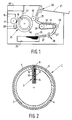
- the image-forming device shown in Fig. 1 is provided with the image-recording medium 15 which will be described in detail hereinafter with reference to Fig. 2.
- the image-recording medium 15 passes through an image-forming station 16 where its surface is provided with a uniform layer of toner powder of a resistivity of about 10 5 ⁇ m, by means 20 constructed as described in US Patent 3 946 402.
- the powdered surface of the image-recording medium 15 is then fed to an image-forming zone 18 where a magnetic roller 17 is disposed a short distance from the surface of the medium 15 and comprises a rotatable electrically conductive shell and a stationary magnet system disposed inside the shell.
- the stationary magnet system comprises a ferromagnetic knife blade clamped between like poles of two magnets and is constructed as described in EP-A-0 304 983.
- a sheet of paper is taken from the supply stack 25 by a roller 26 and is fed via belts 27 and rollers 28 and 29 to a heating station 30.
- the latter comprises a belt 31 trained around a heated roller 32.
- the paper sheet is heated by contact with the belt 31.
- the sheet of paper thus heated is now passed between the roller 19 and the pressure roller 35, the softened powder image on the roller 19 being completely transferred to the sheet of paper.
- the temperatures of the belt 31 and the roller 19 are so adapted to one another that the image fuses to the sheet of paper.
- the sheet of paper provided with an image is fed via conveyor rollers 36 to a collecting tray 37.
- Unit 40 comprises an electronic circuit which converts the optical information of an original into electrical signals which are fed, via wires 41 provided with sliding contacts, and via conductive tracks 42 formed in the side wall of the image-recording medium 15, to control elements 3 (see Fig. 2) connected to the tracks 42.
- the information is fed serially line by line to the shift register of the integrated circuits of the elements 3. If the shift registers are completely full in accordance with the information of one line, that information is set in the output register and the electrodes 6, 5 (see Fig. 2) are energised or not via the drivers depending on the signal. While this line is being printed, the information of the next line is fed to the shift registers.
- Unit 40 also comprises the known control electronics for controlling, regulating and monitoring the various functions of the image- forming device.
- electrical signals originating from a computer or a data-processing device can be converted in unit 40 to signals fed to the control elements 3.
- the image-recording medium 15 used in the image-forming device of Fig. 1 is shown in diagrammatic cross-section in Fig. 2.
- the image-recording medium 15 shown in Fig. 2 comprises a cylinder 2 and disposed therein an axially extending control element 3 having a construction to be described hereinafter.
- the cylinder 2 is covered with an insulating layer 4, on which image-forming electrodes 5 are disposed and extend in the form of endless tracks parallel to one another at substantially constant spacing from one another in the peripheral direction of the cylinder 2.
- Each image- forming electrode 5 is conductively connected to one control electrode 6 in each case of the control element 3.
- the number of control electrodes 6 of the control element 3 is equal to the number of image-forming electrodes 5, such number determining the quality of images to be formed on the image-recording element 1.
- the number of electrodes 5 is 16 per millimetre, the electrodes 5 having a width of 40 ⁇ m and the inter-electrode distance being about 20 ⁇ m.
- the control element 3 comprises a support 10 provided in known manner with an electrically conductive metal layer (such as copper), the metal layer being converted to a conductive track pattern 12 in known manner.
- the track pattern 12 consists, on the one hand, of the conductive connections between the various electronic components 13 of the control element 3 and, on the other hand, the control electrodes 6 each conductively connected to one image forming electrode 5 in each case.
- the control element 3 also comprises a cover 14 connected in manner known per se (e.g. gluing) to the support 10 so that a box-shaped control element 3 is formed, in which the electronic components are enclosed.
- the electronic components 13 comprise a number of known integrated circuits (IC's) comprising a series-in parallel-out shift register, an output register, and drivers connected thereto with a voltage range of 25 to 50 volts.
- IC's integrated circuits
- Each control electrode 6 is connected to a driver of one of the integrated circuits.
- Figs. 3 and 4 show two different possibilities of operation for the operative image-forming part of the device according to Fig. 1.
- the toner supply roller 20 is at a potential of -60V while the shell of the magnetic roller 17 and the image-forming electrodes of the image-recording medium, when no image is being printed, are at earth potential.
- the image-forming electrodes involved in image formation are at a potential of +40V.
- the toner supply roller 20 is at +100V and the shell of the magnetic roller 17 and the image-forming electrodes 5 are switched to +40V when no image is being printed.
- the image-forming electrodes 5 involved are at earth potential.
- the area free of background which in the starting situation, with the image-forming medium still unused, is between approximately +4 and -4V, is found to decrease relatively rapidly, and after about 300 000 prints of A4 format a situation is reached in which the area is only 0 to -4V and prints free of background can no longer be obtained.
- one or a limited number of images are printed alternately in the situation shown in Fig. 3 and in the situation shown in Fig. 4.
- Switching the image-forming device from one situation to the other is controlled in manner known per se by the unit 40 and takes place in the period between each two successive image-forming cycles.
- the image-forming electrodes 5 and the shell 17 are simultaneously switched so that toner deposition on the image-forming medium is prevented.
- image formation is effected by switching the image-forming electrodes 5 from +40V to 0V
- the image data stored, for example, page-wise in an electronic memory are set in the output register of the drivers in an inverted form in comparison with the situation shown in Fig. 3.
- Electronic circuits for effecting switching over and inverting image data are known to the skilled man and are not therefore described in detail.
- the background-free area after one million prints was still +2 to -3V and the prints were thus still background-free.
- the image-recording medium 15 should not be exposed excessively to a constant-orientation electric field.
- the maximum number of images that may be printed successively in the same printing situation cannot be indicated exactly. It was established that there is always a considerable increase in life if the number of images (A4 format) printed successively in the same situation is less than 10.
- the driver used to switch the image-forming electrodes 5 enable both a positive and negative potential to be switched to the image-forming electrodes (e.g. +40V and -40V)
- the method according to the invention can also be performed by printing one or more images alternately with the image-forming electrodes being brought to the positive (or negative) voltage and then one or more images with the image-forming electrodes 5 at a negative (or positive) voltage.
- the shell 17 acting as the companion electrodes is in that case always at earth potential.
- the voltage at the toner supply roller 20 is in each case switched from a negative potential to a positive potential or vice versa.
- the switching over of this voltage also appears to have a favourable effect on the image-recording medium life.
- Another reason for switching over the voltage to the toner supply roller 20 is that in that case, even if the image-forming electrodes 5 are energised to form an image, the voltage difference between the toner supply roller 20 and the image-recording medium is large enough to deposit a sufficient quantity of toner powder on the image-recording medium surface. If the voltage at the supply roller 20 were not reversed, there would be a risk, when large image areas are required to be printed, of the toner supply being inadequate and the supply of toner in the image-forming zone being exhausted.
- a high-frequency AC voltage is applied between at least those image-forming electrodes which are not involved in image formation and the shell 17.
- the frequency of this AC voltage is selected to be such that no toner power is deposited on the image-recording medium 15 if the image-forming electrodes 5 are not energised to form an image.
- the size of the background-free area depends on the frequency, amplitude and signal shape of the AC voltage. For example, with a block voltage having peak values of +40V and -40V, a background-free area was found from frequencies of about 6 kHz. The maximum size of the background-free area is obtained with a frequency somewhere between 15 and 25 kHz. On application of a block voltage with peak values of +80V and -80V, a background-free area was found at much higher frequencies, the optimum always being achieved at a frequency between 100 and 200 kHz.
- the optimal AC voltage frequency can be readily determined experimentally for a given device and a given toner powder.
- the AC voltage may be of any required shape. Preferably, a block voltage is used.
- the amplitude of the AC voltage is at least 25V and is preferably between 25 and 100V.
- a background-free area of +7 to -8V was determined using the magenta-coloured toner powder described hereinafter, by application to the shell 17 of a block voltage with a frequency of 160 kHz and peak values of +80 and -80V respectively.
- Image recording in these conditions was obtained by switching the image-forming electrodes 5 between +40V, when an image pattern is recorded, and earth potential when no image is recorded.
- the background-free area was +4V to -5V.
- images having a relatively sharper image edge were recorded on application of the AC voltage to the shell 17, particularly towards the end of the life of the image- recording medium 15, as compared with the situation in which no AC voltage is applied.
- the greater image edge sharpness applies particularly to image rear edges as considered in the opposite direction to the direction of transport of the image-recording medium.
- the magnet system 87 shown in Fig. 5 comprises a permanent magnet 86 consisting of an alloy of neodymium, iron and boron. Magnetisable elements 85 and 88 are secured against the poles of a magnet 86 and the ends not connected to the magnet 86 terminate in a gap 93 and gradually narrow in the direction of the gap 93.
- the magnet 86 together with the magnetisable elements 85 and 88 is so dimensioned that the ends of the elements 85 and 88 leading into the gap 93 are magnetically saturated.
- the magnetisable material of the elements 85 and 88 is iron cobalt, which has a high saturation magnetisation and a high permeability.
- the magnet system 87 is so disposed inside the shell 17 that the gap 93, which has a width of 300 micrometres, is situated in the centre of the image-forming zone and the inside of the shell 17 does just not touch the magnetisable elements 85 and 88.
- the magnet system 87 is given in the European patent application 0 573 096.
- the toner powder used had the following composition:
- the larger background-free area obtained by applying a high-frequency AC voltage to the shell 17 can also be used to improve the quality of the images recorded on the image-recording medium 15.
- a new situation is achieved with a better image quality by using a finer toner powder with, for example, a particle size of 7 - 14 micrometres, an acceptable background-free area being obtained of +5 to -5V for example, thanks to the application of an AC voltage to shell 17.
- the embodiment in which a high-frequency AC voltage is applied to the shell 17 can advantageously be combined with the above-described embodiment in which, during image recording, the image-forming electrodes 5 are alternately at positive and then negative voltage.
- the life of the image-recording medium 15 has been found to be lengthened more as a result, while the larger background-free area obtained by applying AC voltage is also achieved.
- the method according to the invention can advantageously be performed by applying to the shell 17 a high-frequency AC voltage having peak values of +40V and -40V, with a frequency which, in the given specific arrangement and the given toner powder, results in the largest background-free area, and by energising the image-forming electrodes, as described hereinbefore with reference to Figs. 3 and 4, at +40V during the image formation and then alternately at -40V.
- the switching over of the potential can again be effected per image or group of images, as already described hereinbefore.
- AC voltage can also be applied to the image-forming electrodes 5, the latter being switched between AC voltage with peak values of, for example, + and - 40V, when they are not involved in image formation, and a positive or negative voltage of 40V when they are so involved, whether this positive or negative voltage is superimposed on the AC voltage.
- the shell 17 is then always at earth potential.
- the AC voltage can be applied to the image-forming electrodes 5 or the shell 15 not just during image recording, but also in periods in which the printing device is in the standby position.
- a constant potential can be applied to the image-forming electrodes 5 and the shell 17, e.g. earth potential or a positive or negative voltage of 40 volts for example.
- a combination of the two is possible, e.g. a situation in which in the standby position there is predominantly a constant voltage applied between the image forming electrodes 5 and the shell 17 with short breaks of a few seconds in which AC voltage is applied to the image-forming electrodes 5 or the shell 17 and the other electrodes (17 or 5) are at each potential.
- the switching over of the voltage e.g.
- each image-forming electrode when triggered to contribute to image recording after the interruption of one or more image lines in which it was not involved in image recording, can be put at a potential which is the opposite to the potential applied when the electrode in question was last involved in image formation. Having regard to the life of the image-recording medium 15, the result obtained in this way is practically the same as the result obtained when switching over of the applied voltage takes place per image. Since the implementation of this variant requires a more complex control circuit than for the variant in which switching is carried out between successive images, the latter variant is preferred.
- the method according to the invention can also be performed in image-forming devices in which the companion electrode is situated beneath the dielectric surface of the image-recording medium and the image-forming electrodes are disposed in the image-forming zone at a short distance above the dielectric surface.
- An image-forming device of this kind is described, for example, in US patent 3 946 402.
- the method according to the invention can be used not only with toner powders having an electrically conductive surface coating consisting, for example, of carbon, a doped metal oxide such as tin oxide doped with fluorine or antimony, or a conductive polymer such as protonised polyaniline complex, such as known from WO 92/22911, but also with electrically conductive toner powders which have obtained their conductivity by electrically conductive material, e.g. the above-mentioned protonised polyaniline complexes, being distributed over the volume of the toner particles.
- electrically conductive surface coating consisting, for example, of carbon, a doped metal oxide such as tin oxide doped with fluorine or antimony, or a conductive polymer such as protonised polyaniline complex, such as known from WO 92/22911, but also with electrically conductive toner powders which have obtained their conductivity by electrically conductive material, e.g. the above-mentioned protonised polyaniline complexes
- a toner powder of this kind can be obtained, for example, by melting 100 g of polyester resin as described above, then distributing 11 g of protonised complex of polyaniline emeraldine and camphorsulphonic acid (prepared in accordance with the instructions of Examples 1 and 3 of the patent application WO 92/22911) in the melt and then 33 g of magnetisable pigment (type Bayferrox B 318 made by Bayer AG, Germany). The homogeneous melt is then cooled to a solid mass and ground and screened to give particles having a particle size of between 10 and 20 micrometres.
- the powder image formed with such toner powder on an image-recording medium 15 can then be transferred by pressure to a sheet of paper or other receiving material and then fixed thereon on by heating, e.g. using (weak) magnetron radiation.
- heating e.g. using (weak) magnetron radiation.
- other fixing methods known per se can be used.
Landscapes
- Physics & Mathematics (AREA)
- General Physics & Mathematics (AREA)
- Printers Or Recording Devices Using Electromagnetic And Radiation Means (AREA)
- Electrophotography Using Other Than Carlson'S Method (AREA)
Abstract
Description
- The invention relates to a method of recording images on an image-recording medium intended for repeated use, the image-recording medium having a dielectric surface, voltage being applied, in accordance with an image pattern for recording, between a set of image-recording electrodes and a companion electrode, one of the two being beneath the dielectric surface and the other some distance above such surface, for the purpose of depositing on the dielectric surface in accordance with the image pattern toner powder situated in the space between the dielectric surface and the electrode disposed thereabove. The invention also relates to an image-forming device for the application of the method.
- Image-forming methods and devices of the above kind are described inter alia in European patents 0191521, 0247694 and 0247699. In these, a toner powder image formed in an image-forming zone on the dielectric surface of an image-recording medium is transferred directly, or indirectly via an intermediate medium, to a receiving material, such as plain paper, and fixed thereon. The image-recording medium is then used again for the next image-recording cycle.
- With this type of image-forming device, it is of course essential that the life of the image-recording medium should be as long as possible. The continual mechanical, electrical and thermal loads on the image- recording medium gradually result in the deterioration thereof, and this is manifest in the form of a decline in the background-free base, i.e. the maximum potential difference between an image-recording electrode and the companion electrode at which toner deposition on the dielectric surface does not exceed a predetermined level. In practice this level will be so fixed that no background is visible on the print.
- The decline in the background-free base is the result of fouling occurring as a result of the repeated stresses and change of electrical properties of the dielectric surface.
- The invention relates to a method of the type described in the preamble, whereby it is possible to increase the life of the image-recording medium. The method according to the invention is characterised in that the image recording is effected how by bringing the image-recording electrodes to a positive potential with respect to the companion electrode and then by bringing them to a negative potential with respect to the companion electrode. It has been found that the decline in the background-free base is appreciably delayed and hence the life of the image-recording medium is considerably lengthened, if the electrical field applied across the dielectric surface of the image-recording medium during the recording of images is regularly reversed in respect of its direction during the life of the image-recording medium.
- According to a first variant of the invention, series of images are printed alternately, the image-recording electrodes being brought to a positive (or negative) potential with respect to the companion electrode in one series of images while in the following series of images they are brought to a potential which is the reverse of the potential applied in the preceding series.
- The term "images" in this context denotes the information transferred to the same side of an image- receiving material. The number of images formed in consecutive series may be equal or differ and in each series is preferably not more than 10, in order to avoid excessively long unilateral loading of the image- recording medium.
- According to a preferred embodiment of this variant, the potential is reversed for each image to be formed. Potential reversal can be obtained in various ways. For example, during the formation of a first image or a first series of images, the image-recording electrodes required to deposit toner on the dielectric surface may be brought to a positive potential of 30 - 40 volts, for example, while the companion electrode and the image-recording electrodes not involved in image formation are at earth potential. During the formation of the next image or the next series of images the image-forming image-recording electrodes are put at a negative potential of 30 - 40 volts while the companion electrode and image-forming electrodes not involved in image formation remain at earth potential or else the image-forming image-recording electrodes are put at earth potential while the companion electrode and the image-recording electrodes not involved in image formation are put at the same potential of about 30 to 40 volts.
- According to a second variant of the invention, a high- frequency AC voltage is applied between the companion electrode and the image-forming electrodes not involved in image-formation, while the image-forming electrodes which are involved in image formation are put at a negative or positive potential (DC voltage), which may or may not be superimposed on the AC voltage already applied. The high-frequency AC voltage has a frequency such that the toner deposition on the image recording medium again remains below a predetermined level (in this case a level such that the print is visually free of background).
- According to one attractive embodiment of this second variant, the high-frequency AC voltage is applied to the companion electrode while the image-forming electrodes, when not involved in image formation, are at earth potential and, when they do contribute to image formation, are put at a positive or negative potential or, as will be described in connection with the first variant, are brought alternately to negative and then positive potential.
- The invention is explained in detail with reference to the following description and accompanying drawings wherein:
- Fig. 1 diagrammatically illustrates an image-forming device according to the invention.
- Fig. 2 is a section of an image-recording medium as used in the device shown in Fig. 1, and
- Figs. 3 and 4 are diagrams showing the electrical circuit of the image-forming and companion electrodes in some embodiments of the invention.
- The image-forming device shown in Fig. 1 is provided with the image-
recording medium 15 which will be described in detail hereinafter with reference to Fig. 2. The image-recording medium 15 passes through an image-formingstation 16 where its surface is provided with a uniform layer of toner powder of a resistivity of about 105Ωm, bymeans 20 constructed as described in US Patent 3 946 402. - The powdered surface of the image-
recording medium 15 is then fed to an image-formingzone 18 where amagnetic roller 17 is disposed a short distance from the surface of themedium 15 and comprises a rotatable electrically conductive shell and a stationary magnet system disposed inside the shell. The stationary magnet system comprises a ferromagnetic knife blade clamped between like poles of two magnets and is constructed as described in EP-A-0 304 983. By applying a voltage between one or more image-forming electrodes of the image-recording medium 15 and the magnetic roller shell acting as a companion electrode, a powder image is formed on the image-recording medium. By the application of pressure this powder image is transferred to a heated rubber-coatedroller 19. A sheet of paper is taken from thesupply stack 25 by aroller 26 and is fed viabelts 27 androllers heating station 30. The latter comprises abelt 31 trained around a heatedroller 32. The paper sheet is heated by contact with thebelt 31. The sheet of paper thus heated is now passed between theroller 19 and thepressure roller 35, the softened powder image on theroller 19 being completely transferred to the sheet of paper. The temperatures of thebelt 31 and theroller 19 are so adapted to one another that the image fuses to the sheet of paper. The sheet of paper provided with an image is fed viaconveyor rollers 36 to a collectingtray 37. -
Unit 40 comprises an electronic circuit which converts the optical information of an original into electrical signals which are fed, viawires 41 provided with sliding contacts, and viaconductive tracks 42 formed in the side wall of the image-recording medium 15, to control elements 3 (see Fig. 2) connected to thetracks 42. The information is fed serially line by line to the shift register of the integrated circuits of the elements 3. If the shift registers are completely full in accordance with the information of one line, that information is set in the output register and theelectrodes 6, 5 (see Fig. 2) are energised or not via the drivers depending on the signal. While this line is being printed, the information of the next line is fed to the shift registers.Unit 40 also comprises the known control electronics for controlling, regulating and monitoring the various functions of the image- forming device. - Apart from optical information originating from an original, electrical signals originating from a computer or a data-processing device can be converted in
unit 40 to signals fed to the control elements 3. - The image-
recording medium 15 used in the image-forming device of Fig. 1 is shown in diagrammatic cross-section in Fig. 2. The image-recording medium 15 shown in Fig. 2 comprises a cylinder 2 and disposed therein an axially extending control element 3 having a construction to be described hereinafter. The cylinder 2 is covered with an insulating layer 4, on which image-formingelectrodes 5 are disposed and extend in the form of endless tracks parallel to one another at substantially constant spacing from one another in the peripheral direction of the cylinder 2. Each image- formingelectrode 5 is conductively connected to onecontrol electrode 6 in each case of the control element 3. The number ofcontrol electrodes 6 of the control element 3 is equal to the number of image-formingelectrodes 5, such number determining the quality of images to be formed on the image-recording element 1. The greater the electrode density, the better the image quality. In the embodiment used here, the number ofelectrodes 5 is 16 per millimetre, theelectrodes 5 having a width of 40 µm and the inter-electrode distance being about 20 µm. - Finally, the pattem of image-forming
electrodes 5 is covered with a smoothdielectric top layer 7 consisting of an approximately 0.8 micrometre thick layer of silicon oxide, the bottom layer portion thereof, in a thickness of about 0.4 micrometre, consisting of SiOx, where x = +/- 0.5 and the top layer portion consists of SiOx where x = +/- 1.5. - The silicon oxide layer is applied by a known sputter technique in a vacuum chamber, silicon being sputtered from a silicon target with argon and oxygen being introduced into the chamber and in the first phase of the sputter process the supply of oxygen is such that SiOx, x = +/- 0.5 is applied and in the second phase the oxygen supply is increased so that SiOx, x = +/- 1.5 is applied.
- The control element 3 comprises a
support 10 provided in known manner with an electrically conductive metal layer (such as copper), the metal layer being converted to aconductive track pattern 12 in known manner. Thetrack pattern 12 consists, on the one hand, of the conductive connections between the variouselectronic components 13 of the control element 3 and, on the other hand, thecontrol electrodes 6 each conductively connected to oneimage forming electrode 5 in each case. Finally, the control element 3 also comprises acover 14 connected in manner known per se (e.g. gluing) to thesupport 10 so that a box-shaped control element 3 is formed, in which the electronic components are enclosed. - The
electronic components 13 comprise a number of known integrated circuits (IC's) comprising a series-in parallel-out shift register, an output register, and drivers connected thereto with a voltage range of 25 to 50 volts. Eachcontrol electrode 6 is connected to a driver of one of the integrated circuits. - Figs. 3 and 4 show two different possibilities of operation for the operative image-forming part of the device according to Fig. 1.
- In the option shown in Fig. 3, the
toner supply roller 20 is at a potential of -60V while the shell of themagnetic roller 17 and the image-forming electrodes of the image-recording medium, when no image is being printed, are at earth potential. When an image is printed, the image-forming electrodes involved in image formation are at a potential of +40V. - In the embodiment shown in Fig. 4, the
toner supply roller 20 is at +100V and the shell of themagnetic roller 17 and the image-formingelectrodes 5 are switched to +40V when no image is being printed. During image-formation, the image-formingelectrodes 5 involved are at earth potential. - If the image-forming device is operated continuously in the embodiment as shown in one of Figs. 3 or 4, the area free of background, which in the starting situation, with the image-forming medium still unused, is between approximately +4 and -4V, is found to decrease relatively rapidly, and after about 300 000 prints of A4 format a situation is reached in which the area is only 0 to -4V and prints free of background can no longer be obtained.
- According to the first variant of the invention, one or a limited number of images (A4 format) are printed alternately in the situation shown in Fig. 3 and in the situation shown in Fig. 4. Switching the image-forming device from one situation to the other is controlled in manner known per se by the
unit 40 and takes place in the period between each two successive image-forming cycles. During switching over, the image-formingelectrodes 5 and theshell 17 are simultaneously switched so that toner deposition on the image-forming medium is prevented. Since, in the situation shown in Fig. 4, image formation is effected by switching the image-formingelectrodes 5 from +40V to 0V, the image data stored, for example, page-wise in an electronic memory are set in the output register of the drivers in an inverted form in comparison with the situation shown in Fig. 3. Electronic circuits for effecting switching over and inverting image data are known to the skilled man and are not therefore described in detail. - According to the invention, a considerable increase in the life of the image-recording medium is achieved. After 500 000 prints, the area free of background had in all cases dropped only 1 - 1.5V and prints free from background were still obtained.
- In one preferred embodiment of the invention, in which after each image is printed the situation is switched from one situation to the other, the background-free area after one million prints was still +2 to -3V and the prints were thus still background-free.
- According to the invention it is important that the image-
recording medium 15 should not be exposed excessively to a constant-orientation electric field. The maximum number of images that may be printed successively in the same printing situation cannot be indicated exactly. It was established that there is always a considerable increase in life if the number of images (A4 format) printed successively in the same situation is less than 10. If the drivers used to switch the image-formingelectrodes 5 enable both a positive and negative potential to be switched to the image-forming electrodes (e.g. +40V and -40V), the method according to the invention can also be performed by printing one or more images alternately with the image-forming electrodes being brought to the positive (or negative) voltage and then one or more images with the image-formingelectrodes 5 at a negative (or positive) voltage. Theshell 17 acting as the companion electrodes is in that case always at earth potential. - On reversal of the electrical field, as shown in Figs. 3 and 4, the voltage at the
toner supply roller 20 is in each case switched from a negative potential to a positive potential or vice versa. The switching over of this voltage also appears to have a favourable effect on the image-recording medium life. Another reason for switching over the voltage to thetoner supply roller 20 is that in that case, even if the image-formingelectrodes 5 are energised to form an image, the voltage difference between thetoner supply roller 20 and the image-recording medium is large enough to deposit a sufficient quantity of toner powder on the image-recording medium surface. If the voltage at thesupply roller 20 were not reversed, there would be a risk, when large image areas are required to be printed, of the toner supply being inadequate and the supply of toner in the image-forming zone being exhausted. - In order to investigate the effect of reversing just the voltage at the
supply roller 20 on the life of the image-recording medium 5, images were printed in the situation shown in Fig. 3, in which the voltage at thesupply roller 20 was always reversed in the period between two successive images. No background-free prints could be obtained after approximately 400 000 images. - According to the second variant of the invention, a high-frequency AC voltage is applied between at least those image-forming electrodes which are not involved in image formation and the
shell 17. The frequency of this AC voltage is selected to be such that no toner power is deposited on the image-recording medium 15 if the image-formingelectrodes 5 are not energised to form an image. In this variant of the invention, in comparison with the variants described hereinbefore, it was found that in the starting situation - i.e. with the image-recording medium still unused - the background-free area was considerably larger than in the previously described starting situations. - The size of the background-free area depends on the frequency, amplitude and signal shape of the AC voltage. For example, with a block voltage having peak values of +40V and -40V, a background-free area was found from frequencies of about 6 kHz. The maximum size of the background-free area is obtained with a frequency somewhere between 15 and 25 kHz. On application of a block voltage with peak values of +80V and -80V, a background-free area was found at much higher frequencies, the optimum always being achieved at a frequency between 100 and 200 kHz. The optimal AC voltage frequency can be readily determined experimentally for a given device and a given toner powder. The AC voltage may be of any required shape. Preferably, a block voltage is used. The amplitude of the AC voltage is at least 25V and is preferably between 25 and 100V.
- In a printing device of the type as described with reference to Fig. 3, in which a stationary magnet system was again disposed inside the
shell 17 as described hereinafter with reference to Fig. 5, a background-free area of +7 to -8V was determined using the magenta-coloured toner powder described hereinafter, by application to theshell 17 of a block voltage with a frequency of 160 kHz and peak values of +80 and -80V respectively. Image recording in these conditions was obtained by switching the image-formingelectrodes 5 between +40V, when an image pattern is recorded, and earth potential when no image is recorded. When theshell 17 was connected to earth, the background-free area was +4V to -5V. - Apart from the larger background-free base, resulting in a longer life of the image-recording medium, images having a relatively sharper image edge were recorded on application of the AC voltage to the
shell 17, particularly towards the end of the life of the image-recording medium 15, as compared with the situation in which no AC voltage is applied. The greater image edge sharpness applies particularly to image rear edges as considered in the opposite direction to the direction of transport of the image-recording medium. - The
magnet system 87 shown in Fig. 5 comprises apermanent magnet 86 consisting of an alloy of neodymium, iron and boron.Magnetisable elements magnet 86 and the ends not connected to themagnet 86 terminate in agap 93 and gradually narrow in the direction of thegap 93. Themagnet 86 together with themagnetisable elements elements gap 93 are magnetically saturated. The magnetisable material of theelements - The
magnet system 87 is so disposed inside theshell 17 that thegap 93, which has a width of 300 micrometres, is situated in the centre of the image-forming zone and the inside of theshell 17 does just not touch themagnetisable elements magnet system 87 is given in the European patent application 0 573 096. - The toner powder used had the following composition:
- thermoplastic polyester resin type Atlac 500T
(made by ICI, England), derived from oxypropylene bisphenol A and fumaric acid - 1 percent by volume of carbonyl iron having a particle size of about
2 micrometres (BASF, Germany, type HS) - 3% by weight of red dye (Basonyl Rot 560 - C.I. Basic Violet 11:1) in the perchlorate form,
and had a resistivity of about 105Ωm obtained by coating the powder particles (which were of a size between 11 and 20 micrometres) with fluorine-doped tin oxide in the manner described in European patent application number 0 441 426. - The larger background-free area obtained by applying a high-frequency AC voltage to the
shell 17 can also be used to improve the quality of the images recorded on the image-recording medium 15. For example, in a situation in which, without using AC voltage, there is a background-free area from +4 to -4V, using a toner powder with a particle size of 11 - 20 micrometres and, with the application of the correct AC voltage, a background-free area from +7 to -7V is obtained, a new situation is achieved with a better image quality by using a finer toner powder with, for example, a particle size of 7 - 14 micrometres, an acceptable background-free area being obtained of +5 to -5V for example, thanks to the application of an AC voltage to shell 17. - The embodiment in which a high-frequency AC voltage is applied to the
shell 17 can advantageously be combined with the above-described embodiment in which, during image recording, the image-formingelectrodes 5 are alternately at positive and then negative voltage. The life of the image-recording medium 15 has been found to be lengthened more as a result, while the larger background-free area obtained by applying AC voltage is also achieved. For example, the method according to the invention can advantageously be performed by applying to the shell 17 a high-frequency AC voltage having peak values of +40V and -40V, with a frequency which, in the given specific arrangement and the given toner powder, results in the largest background-free area, and by energising the image-forming electrodes, as described hereinbefore with reference to Figs. 3 and 4, at +40V during the image formation and then alternately at -40V. The switching over of the potential can again be effected per image or group of images, as already described hereinbefore. - Although the embodiment in which AC voltage is applied has been illustrated above in connection with the application of AC voltage to the
shell 17, it will be clear that the AC voltage can also be applied to the image-formingelectrodes 5, the latter being switched between AC voltage with peak values of, for example, + and - 40V, when they are not involved in image formation, and a positive or negative voltage of 40V when they are so involved, whether this positive or negative voltage is superimposed on the AC voltage. Theshell 17 is then always at earth potential. - The AC voltage can be applied to the image-forming
electrodes 5 or theshell 15 not just during image recording, but also in periods in which the printing device is in the standby position. Alternatively, in the latter periods, a constant potential can be applied to the image-formingelectrodes 5 and theshell 17, e.g. earth potential or a positive or negative voltage of 40 volts for example. A combination of the two is possible, e.g. a situation in which in the standby position there is predominantly a constant voltage applied between theimage forming electrodes 5 and theshell 17 with short breaks of a few seconds in which AC voltage is applied to the image-formingelectrodes 5 or theshell 17 and the other electrodes (17 or 5) are at each potential. The switching over of the voltage (e.g. from +40 to -40V or vice versa) applied to the image-formingelectrodes 5 can also take place, not only between consecutive images or group of images, as indicated in the embodiments described above, but also during the recording of the same image. Thus each image-forming electrode, when triggered to contribute to image recording after the interruption of one or more image lines in which it was not involved in image recording, can be put at a potential which is the opposite to the potential applied when the electrode in question was last involved in image formation. Having regard to the life of the image-recording medium 15, the result obtained in this way is practically the same as the result obtained when switching over of the applied voltage takes place per image. Since the implementation of this variant requires a more complex control circuit than for the variant in which switching is carried out between successive images, the latter variant is preferred. - It will also be clear that the method according to the invention can also be performed in image-forming devices in which the companion electrode is situated beneath the dielectric surface of the image-recording medium and the image-forming electrodes are disposed in the image-forming zone at a short distance above the dielectric surface. An image-forming device of this kind is described, for example, in US patent 3 946 402.
- The method according to the invention can be used not only with toner powders having an electrically conductive surface coating consisting, for example, of carbon, a doped metal oxide such as tin oxide doped with fluorine or antimony, or a conductive polymer such as protonised polyaniline complex, such as known from WO 92/22911, but also with electrically conductive toner powders which have obtained their conductivity by electrically conductive material, e.g. the above-mentioned protonised polyaniline complexes, being distributed over the volume of the toner particles. A toner powder of this kind can be obtained, for example, by melting 100 g of polyester resin as described above, then distributing 11 g of protonised complex of polyaniline emeraldine and camphorsulphonic acid (prepared in accordance with the instructions of Examples 1 and 3 of the patent application WO 92/22911) in the melt and then 33 g of magnetisable pigment (type Bayferrox B 318 made by Bayer AG, Germany). The homogeneous melt is then cooled to a solid mass and ground and screened to give particles having a particle size of between 10 and 20 micrometres. The powder image formed with such toner powder on an image-
recording medium 15 can then be transferred by pressure to a sheet of paper or other receiving material and then fixed thereon on by heating, e.g. using (weak) magnetron radiation. Of course other fixing methods known per se can be used.
Claims (12)
- A method of recording images on an image-recording medium (15) intended for repeated use, the image- recording medium having a dielectric surface (7), voltage being applied, in accordance with an image pattern for recording, between a set of image-recording electrodes (5) and a companion electrode (17), one of the two being beneath the dielectric surface and the other some distance above such surface, for the purpose of depositing on the dielectric surface in accordance with the image pattern toner powder situated in the space between the dielectric surface and the electrode disposed thereabove, characterised in that the image recording is effected now by bringing the image- recording electrodes (5) to a positive potential with respect to the companion electrode (17) and then by bringing the image recording electrodes (5) to a negative potential with respect to the companion electrode.
- A method according to claim 1, characterised in that a first series of images is recorded by bringing the image-recording electrodes (5) to a positive or negative potential with respect to the companion electrode (17) and a second series of images is recorded thereafter by bringing the image-recording electrodes (5) to the opposite potential, the number of images in the two series being equal or different.
- A method according to claim 2, characterised in that the number of images in the two series is 1.
- A method according to one or more of the preceding claims, characterised in that the companion electrode (17) is kept at a fixed potential and the image-forming electrodes (5), when they contribute to image formation, are brought alternately to a positive and to a negative potential with respect to the companion electrode (17).
- A method according to one or more of the preceding claims, characterised in that the companion electrode (17) and the image-forming electrodes (5) are switched between a first and a second potential.
- A method according to claim 1, characterised in that a high-frequency AC voltage is applied between the companion electrode (17) and the image-forming electrodes (15).
- A method according to claim 6, characterised in that the AC voltage is applied to the companion electrode (17) and the image-forming electrodes (15) are switched between earth and a DC voltage.
- A method according to claim 7, characterised in that the DC voltage applied to the image-forming electrodes (5) is alternately positive and negative.
- An image-forming device comprising an image- recording medium (15) with a dielectric surface (7), an image-forming zone (18) where the dielectric surface (7) is situated between a set of each separately triggerable image-forming electrodes (5) and a companion electrode (17), one of the two (5 or 17) being situated closely beneath the dielectric surface (7) and the other a short distance above said surface, control means (40) for energising the image-forming electrodes (5) in accordance with an image pattem for recording in order to deposit on the dielectric surface (7) in accordance with said image pattern toner powder supplied to the image-forming zone (18), characterised in that the control means (40) comprise means whereby the image-forming electrodes (5) can be switched to a positive and to a negative potential with respect to the companion electrode (17).
- An image-forming device according to claim 9, characterised in that the control means (40) comprise means for applying a high-frequency AC voltage to the companion electrode (17) or to the image-forming electrodes (5).
- An image-forming device according to claim 9, comprising toner supply means (20) disposed in front of the image-forming zone (18) for applying a layer of toner powder to the image-recording medium (15), under the influence of an electrical field applied between the toner supply means (20) and the image-recording medium (15), characterised in that means are provided for reversing the direction of the electrical field between the toner supply means (20) and the image- recording medium (15) coupled with reversal of the electrical field in the image-forming zone (18).
- An image-forming device comprising an image- recording medium (15) with a dielectric surface (7), an image-forming zone (18) where the dielectric surface (7) is situated between a set of each separately triggerable image-forming electrodes (5) and a companion electrode (17), one of the two (5 or 17) being situated closely beneath the dielectric surface (7) and the other a short distance above said surface, toner supply means (20) disposed in front of the image- forming zone (18) for applying a layer of toner powder to the image-recording medium (15), under the influence of an electrical field applied between the toner supply means (20) and the image-recording medium (15), control means (40) for energising the image-forming electrodes (5) in accordance with an image pattern for recording in order to deposit toner powder on the dielectric surface (7) in accordance with said image pattern, characterised in that means are provided to reverse the direction of the electrical field between the toner supply means (20) and the image-recording medium (15).
Applications Claiming Priority (2)
| Application Number | Priority Date | Filing Date | Title |
|---|---|---|---|
| NL9402196A NL9402196A (en) | 1994-12-23 | 1994-12-23 | Method for recording images, as well as an imaging device for applying the method. |
| NL9402196 | 1994-12-23 |
Publications (2)
| Publication Number | Publication Date |
|---|---|
| EP0718721A1 true EP0718721A1 (en) | 1996-06-26 |
| EP0718721B1 EP0718721B1 (en) | 2000-09-06 |
Family
ID=19865063
Family Applications (1)
| Application Number | Title | Priority Date | Filing Date |
|---|---|---|---|
| EP95203521A Expired - Lifetime EP0718721B1 (en) | 1994-12-23 | 1995-12-15 | Method of recording images, and an image-forming device for application of the method |
Country Status (5)
| Country | Link |
|---|---|
| US (1) | US6040847A (en) |
| EP (1) | EP0718721B1 (en) |
| JP (1) | JP3308440B2 (en) |
| DE (1) | DE69518728T2 (en) |
| NL (1) | NL9402196A (en) |
Cited By (1)
| Publication number | Priority date | Publication date | Assignee | Title |
|---|---|---|---|---|
| WO2010072646A1 (en) * | 2008-12-23 | 2010-07-01 | Oce-Technologies B.V. | Method for operating an image-forming device and an image forming device for application of the method |
Families Citing this family (1)
| Publication number | Priority date | Publication date | Assignee | Title |
|---|---|---|---|---|
| KR100850716B1 (en) * | 2006-12-01 | 2008-08-06 | 삼성전자주식회사 | Image Former and Manufacturing Method Thereof |
Citations (10)
| Publication number | Priority date | Publication date | Assignee | Title |
|---|---|---|---|---|
| US3946402A (en) | 1974-05-28 | 1976-03-23 | Minnesota Mining & Manufacturing Company | Toner applicator for electrographic recording system |
| EP0191521A1 (en) | 1985-02-06 | 1986-08-20 | Océ-Nederland B.V. | Printing device |
| EP0247694A1 (en) | 1986-05-29 | 1987-12-02 | Océ-Nederland B.V. | Image-forming element for an electrostatic printer, and a printer in which an element of this kind is used |
| EP0247699A1 (en) | 1986-05-29 | 1987-12-02 | Océ-Nederland B.V. | Image-forming element for an electrostatic printer, and a printer in which an element of this kind is used |
| JPS63144364A (en) * | 1986-12-09 | 1988-06-16 | Canon Inc | Image forming device |
| EP0304983A1 (en) | 1987-08-25 | 1989-03-01 | Océ-Nederland B.V. | A printing device having a magnetic roller comprising a stationary ferromagnetic knife blade enclosed between like magnetic poles |
| JPH04156351A (en) * | 1990-10-19 | 1992-05-28 | Casio Comput Co Ltd | electrostatic recording device |
| WO1992022911A1 (en) | 1991-06-12 | 1992-12-23 | Uniax Corporation | Processible forms of electrically conductive polyaniline and conductive products formed therefrom |
| EP0573096A1 (en) | 1992-06-04 | 1993-12-08 | Océ-Nederland B.V. | Image-forming device |
| EP0595388A1 (en) * | 1992-10-30 | 1994-05-04 | Océ-Nederland B.V. | A process for the preparation of an image-forming element and a printing device for reproducing information |
Family Cites Families (5)
| Publication number | Priority date | Publication date | Assignee | Title |
|---|---|---|---|---|
| JPS5818649A (en) * | 1981-07-27 | 1983-02-03 | Ricoh Co Ltd | Recording method |
| JPS59102341U (en) * | 1982-12-28 | 1984-07-10 | ソニー株式会社 | printer |
| JPS59164153A (en) * | 1983-03-09 | 1984-09-17 | Canon Inc | Image recording apparatus |
| JPS59204861A (en) * | 1983-05-09 | 1984-11-20 | Canon Inc | Image recording device |
| JPH0310313A (en) * | 1989-06-07 | 1991-01-17 | Nec Gumma Ltd | Input signal converter |
-
1994
- 1994-12-23 NL NL9402196A patent/NL9402196A/en not_active Application Discontinuation
-
1995
- 1995-12-12 JP JP34640395A patent/JP3308440B2/en not_active Expired - Fee Related
- 1995-12-15 DE DE69518728T patent/DE69518728T2/en not_active Expired - Lifetime
- 1995-12-15 EP EP95203521A patent/EP0718721B1/en not_active Expired - Lifetime
- 1995-12-20 US US08/575,617 patent/US6040847A/en not_active Expired - Fee Related
Patent Citations (10)
| Publication number | Priority date | Publication date | Assignee | Title |
|---|---|---|---|---|
| US3946402A (en) | 1974-05-28 | 1976-03-23 | Minnesota Mining & Manufacturing Company | Toner applicator for electrographic recording system |
| EP0191521A1 (en) | 1985-02-06 | 1986-08-20 | Océ-Nederland B.V. | Printing device |
| EP0247694A1 (en) | 1986-05-29 | 1987-12-02 | Océ-Nederland B.V. | Image-forming element for an electrostatic printer, and a printer in which an element of this kind is used |
| EP0247699A1 (en) | 1986-05-29 | 1987-12-02 | Océ-Nederland B.V. | Image-forming element for an electrostatic printer, and a printer in which an element of this kind is used |
| JPS63144364A (en) * | 1986-12-09 | 1988-06-16 | Canon Inc | Image forming device |
| EP0304983A1 (en) | 1987-08-25 | 1989-03-01 | Océ-Nederland B.V. | A printing device having a magnetic roller comprising a stationary ferromagnetic knife blade enclosed between like magnetic poles |
| JPH04156351A (en) * | 1990-10-19 | 1992-05-28 | Casio Comput Co Ltd | electrostatic recording device |
| WO1992022911A1 (en) | 1991-06-12 | 1992-12-23 | Uniax Corporation | Processible forms of electrically conductive polyaniline and conductive products formed therefrom |
| EP0573096A1 (en) | 1992-06-04 | 1993-12-08 | Océ-Nederland B.V. | Image-forming device |
| EP0595388A1 (en) * | 1992-10-30 | 1994-05-04 | Océ-Nederland B.V. | A process for the preparation of an image-forming element and a printing device for reproducing information |
Non-Patent Citations (2)
| Title |
|---|
| PATENT ABSTRACTS OF JAPAN vol. 012, no. 406 (P - 777) 27 October 1988 (1988-10-27) * |
| PATENT ABSTRACTS OF JAPAN vol. 016, no. 450 (M - 1312) 18 September 1992 (1992-09-18) * |
Cited By (4)
| Publication number | Priority date | Publication date | Assignee | Title |
|---|---|---|---|---|
| WO2010072646A1 (en) * | 2008-12-23 | 2010-07-01 | Oce-Technologies B.V. | Method for operating an image-forming device and an image forming device for application of the method |
| CN102265225A (en) * | 2008-12-23 | 2011-11-30 | 奥西-技术有限公司 | Method for operating an image-forming device and an image forming device for application of the method |
| US8335459B2 (en) | 2008-12-23 | 2012-12-18 | Oce-Technologies B.V. | Method for operating an image-forming device and an image forming device for application of the method |
| CN102265225B (en) * | 2008-12-23 | 2014-06-04 | 奥西-技术有限公司 | Method for operating imaging device and imaging device applying the method |
Also Published As
| Publication number | Publication date |
|---|---|
| JP3308440B2 (en) | 2002-07-29 |
| NL9402196A (en) | 1996-08-01 |
| JPH08238791A (en) | 1996-09-17 |
| DE69518728D1 (en) | 2000-10-12 |
| US6040847A (en) | 2000-03-21 |
| DE69518728T2 (en) | 2001-05-31 |
| EP0718721B1 (en) | 2000-09-06 |
Similar Documents
| Publication | Publication Date | Title |
|---|---|---|
| EP0191521B1 (en) | Printing device | |
| US5508723A (en) | Electric field potential control device for an image forming apparatus | |
| EP0247699B1 (en) | Image-forming element for an electrostatic printer, and a printer in which an element of this kind is used | |
| US3306193A (en) | Electrostatic screen printing with magnetic conveyer and moving base electrode | |
| JPH03196062A (en) | Perforated head for direct electrostatic printing | |
| KR970004165B1 (en) | Printing device | |
| US5812170A (en) | Electrostatic printing method and apparatus employing a whisker write head | |
| US5889544A (en) | Electrographic printer with multiple transfer electrodes | |
| EP0718721B1 (en) | Method of recording images, and an image-forming device for application of the method | |
| GB2042278A (en) | Forming electrostatic images | |
| EP0635768B1 (en) | Image-forming device and an image-recording element for use therein | |
| US4728971A (en) | Image-forming element for an electrostatic printer with helical shaped electrodes | |
| EP2382511B1 (en) | Method for operating an image-forming device and an image forming device for application of the method | |
| EP0573096B1 (en) | Image-forming device | |
| EP0000408A1 (en) | Process for magnetically transferring a powder image | |
| EP0066431B1 (en) | Toner transport system for electrographic imaging | |
| US4243726A (en) | Structured donor sheet for high-resolution non-impact printer | |
| JPH04285989A (en) | Method for developing magnetic latent image and magnetic recording device | |
| NL9302135A (en) | Imaging device, as well as an image recording element for use therein. |
Legal Events
| Date | Code | Title | Description |
|---|---|---|---|
| PUAI | Public reference made under article 153(3) epc to a published international application that has entered the european phase |
Free format text: ORIGINAL CODE: 0009012 |
|
| AK | Designated contracting states |
Kind code of ref document: A1 Designated state(s): DE FR GB IT NL |
|
| 17P | Request for examination filed |
Effective date: 19961207 |
|
| RAP1 | Party data changed (applicant data changed or rights of an application transferred) |
Owner name: OCE-TECHNOLOGIES B.V. |
|
| 17Q | First examination report despatched |
Effective date: 19990205 |
|
| GRAG | Despatch of communication of intention to grant |
Free format text: ORIGINAL CODE: EPIDOS AGRA |
|
| GRAG | Despatch of communication of intention to grant |
Free format text: ORIGINAL CODE: EPIDOS AGRA |
|
| GRAH | Despatch of communication of intention to grant a patent |
Free format text: ORIGINAL CODE: EPIDOS IGRA |
|
| GRAH | Despatch of communication of intention to grant a patent |
Free format text: ORIGINAL CODE: EPIDOS IGRA |
|
| GRAA | (expected) grant |
Free format text: ORIGINAL CODE: 0009210 |
|
| AK | Designated contracting states |
Kind code of ref document: B1 Designated state(s): DE FR GB IT NL |
|
| REF | Corresponds to: |
Ref document number: 69518728 Country of ref document: DE Date of ref document: 20001012 |
|
| ITF | It: translation for a ep patent filed | ||
| ET | Fr: translation filed | ||
| PLBE | No opposition filed within time limit |
Free format text: ORIGINAL CODE: 0009261 |
|
| STAA | Information on the status of an ep patent application or granted ep patent |
Free format text: STATUS: NO OPPOSITION FILED WITHIN TIME LIMIT |
|
| 26N | No opposition filed | ||
| REG | Reference to a national code |
Ref country code: GB Ref legal event code: IF02 |
|
| PGFP | Annual fee paid to national office [announced via postgrant information from national office to epo] |
Ref country code: NL Payment date: 20041216 Year of fee payment: 10 |
|
| PG25 | Lapsed in a contracting state [announced via postgrant information from national office to epo] |
Ref country code: IT Free format text: LAPSE BECAUSE OF NON-PAYMENT OF DUE FEES;WARNING: LAPSES OF ITALIAN PATENTS WITH EFFECTIVE DATE BEFORE 2007 MAY HAVE OCCURRED AT ANY TIME BEFORE 2007. THE CORRECT EFFECTIVE DATE MAY BE DIFFERENT FROM THE ONE RECORDED. Effective date: 20051215 |
|
| PG25 | Lapsed in a contracting state [announced via postgrant information from national office to epo] |
Ref country code: NL Free format text: LAPSE BECAUSE OF NON-PAYMENT OF DUE FEES Effective date: 20060701 |
|
| NLV4 | Nl: lapsed or anulled due to non-payment of the annual fee |
Effective date: 20060701 |
|
| PGFP | Annual fee paid to national office [announced via postgrant information from national office to epo] |
Ref country code: GB Payment date: 20121220 Year of fee payment: 18 |
|
| PGFP | Annual fee paid to national office [announced via postgrant information from national office to epo] |
Ref country code: DE Payment date: 20121220 Year of fee payment: 18 Ref country code: FR Payment date: 20130130 Year of fee payment: 18 |
|
| REG | Reference to a national code |
Ref country code: DE Ref legal event code: R119 Ref document number: 69518728 Country of ref document: DE |
|
| GBPC | Gb: european patent ceased through non-payment of renewal fee |
Effective date: 20131215 |
|
| REG | Reference to a national code |
Ref country code: FR Ref legal event code: ST Effective date: 20140829 |
|
| REG | Reference to a national code |
Ref country code: DE Ref legal event code: R119 Ref document number: 69518728 Country of ref document: DE Effective date: 20140701 |
|
| PG25 | Lapsed in a contracting state [announced via postgrant information from national office to epo] |
Ref country code: DE Free format text: LAPSE BECAUSE OF NON-PAYMENT OF DUE FEES Effective date: 20140701 |
|
| PG25 | Lapsed in a contracting state [announced via postgrant information from national office to epo] |
Ref country code: FR Free format text: LAPSE BECAUSE OF NON-PAYMENT OF DUE FEES Effective date: 20131231 Ref country code: GB Free format text: LAPSE BECAUSE OF NON-PAYMENT OF DUE FEES Effective date: 20131215 |