EP0718215A1 - Double wall underground tank structure using composite material and method of manufacturing the same - Google Patents
Double wall underground tank structure using composite material and method of manufacturing the same Download PDFInfo
- Publication number
- EP0718215A1 EP0718215A1 EP95924504A EP95924504A EP0718215A1 EP 0718215 A1 EP0718215 A1 EP 0718215A1 EP 95924504 A EP95924504 A EP 95924504A EP 95924504 A EP95924504 A EP 95924504A EP 0718215 A1 EP0718215 A1 EP 0718215A1
- Authority
- EP
- European Patent Office
- Prior art keywords
- tank
- ply
- fabric
- inches
- inch
- Prior art date
- Legal status (The legal status is an assumption and is not a legal conclusion. Google has not performed a legal analysis and makes no representation as to the accuracy of the status listed.)
- Withdrawn
Links
- 239000002131 composite material Substances 0.000 title claims abstract description 105
- 238000004519 manufacturing process Methods 0.000 title description 12
- 239000002184 metal Substances 0.000 claims abstract description 69
- 239000007788 liquid Substances 0.000 claims abstract description 33
- 229910000831 Steel Inorganic materials 0.000 claims abstract description 32
- 239000010959 steel Substances 0.000 claims abstract description 32
- 239000000463 material Substances 0.000 claims abstract description 27
- 229920001187 thermosetting polymer Polymers 0.000 claims abstract description 19
- 238000000034 method Methods 0.000 claims abstract description 16
- 239000011159 matrix material Substances 0.000 claims abstract description 15
- 239000002990 reinforced plastic Substances 0.000 claims abstract description 10
- 239000004744 fabric Substances 0.000 claims description 149
- 239000011152 fibreglass Substances 0.000 claims description 91
- 239000011521 glass Substances 0.000 claims description 33
- 229920005989 resin Polymers 0.000 claims description 31
- 239000011347 resin Substances 0.000 claims description 31
- 238000003860 storage Methods 0.000 claims description 26
- 229920000728 polyester Polymers 0.000 claims description 24
- PPBRXRYQALVLMV-UHFFFAOYSA-N Styrene Chemical compound C=CC1=CC=CC=C1 PPBRXRYQALVLMV-UHFFFAOYSA-N 0.000 claims description 23
- 230000006835 compression Effects 0.000 claims description 21
- 238000007906 compression Methods 0.000 claims description 21
- 229920001567 vinyl ester resin Polymers 0.000 claims description 13
- 238000005520 cutting process Methods 0.000 claims description 10
- 230000002787 reinforcement Effects 0.000 claims description 10
- 238000003466 welding Methods 0.000 claims description 10
- 239000002985 plastic film Substances 0.000 claims description 9
- 238000004804 winding Methods 0.000 claims description 8
- 238000012360 testing method Methods 0.000 claims description 7
- 238000007789 sealing Methods 0.000 claims description 5
- 239000003365 glass fiber Substances 0.000 claims description 4
- 239000002952 polymeric resin Substances 0.000 claims description 4
- 229920003002 synthetic resin Polymers 0.000 claims description 4
- 229910000975 Carbon steel Inorganic materials 0.000 claims description 3
- 239000000470 constituent Substances 0.000 claims description 3
- 239000004576 sand Substances 0.000 claims description 3
- 238000009966 trimming Methods 0.000 claims description 3
- 239000004698 Polyethylene Substances 0.000 claims description 2
- 229910001361 White metal Inorganic materials 0.000 claims description 2
- 239000010962 carbon steel Substances 0.000 claims description 2
- 238000010030 laminating Methods 0.000 claims description 2
- 238000010422 painting Methods 0.000 claims description 2
- 229920003023 plastic Polymers 0.000 claims description 2
- 239000004033 plastic Substances 0.000 claims description 2
- -1 polyethylene Polymers 0.000 claims description 2
- 229920000573 polyethylene Polymers 0.000 claims description 2
- 238000003825 pressing Methods 0.000 claims description 2
- 238000005096 rolling process Methods 0.000 claims description 2
- 238000007493 shaping process Methods 0.000 claims description 2
- 239000010969 white metal Substances 0.000 claims description 2
- 230000004323 axial length Effects 0.000 claims 2
- 150000001491 aromatic compounds Chemical class 0.000 claims 1
- 239000000835 fiber Substances 0.000 claims 1
- 239000002245 particle Substances 0.000 claims 1
- 230000007797 corrosion Effects 0.000 abstract description 9
- 238000005260 corrosion Methods 0.000 abstract description 9
- 239000002648 laminated material Substances 0.000 abstract description 2
- 239000011257 shell material Substances 0.000 description 44
- 239000004645 polyester resin Substances 0.000 description 12
- 229920001225 polyester resin Polymers 0.000 description 12
- 238000010276 construction Methods 0.000 description 11
- 239000000126 substance Substances 0.000 description 11
- 239000003209 petroleum derivative Substances 0.000 description 9
- 239000000203 mixture Substances 0.000 description 8
- 230000006378 damage Effects 0.000 description 4
- 239000000446 fuel Substances 0.000 description 3
- 231100001261 hazardous Toxicity 0.000 description 3
- 239000002689 soil Substances 0.000 description 3
- 238000005507 spraying Methods 0.000 description 3
- LFQSCWFLJHTTHZ-UHFFFAOYSA-N Ethanol Chemical compound CCO LFQSCWFLJHTTHZ-UHFFFAOYSA-N 0.000 description 2
- 229920002472 Starch Polymers 0.000 description 2
- 208000013201 Stress fracture Diseases 0.000 description 2
- 150000001298 alcohols Chemical class 0.000 description 2
- 239000011230 binding agent Substances 0.000 description 2
- 238000001514 detection method Methods 0.000 description 2
- 238000007654 immersion Methods 0.000 description 2
- 238000002329 infrared spectrum Methods 0.000 description 2
- 235000019698 starch Nutrition 0.000 description 2
- 239000008107 starch Substances 0.000 description 2
- 208000010392 Bone Fractures Diseases 0.000 description 1
- 206010017076 Fracture Diseases 0.000 description 1
- 208000027418 Wounds and injury Diseases 0.000 description 1
- 239000000654 additive Substances 0.000 description 1
- 230000000996 additive effect Effects 0.000 description 1
- 238000003915 air pollution Methods 0.000 description 1
- 239000003054 catalyst Substances 0.000 description 1
- 239000003795 chemical substances by application Substances 0.000 description 1
- 238000007796 conventional method Methods 0.000 description 1
- 230000001419 dependent effect Effects 0.000 description 1
- 230000007613 environmental effect Effects 0.000 description 1
- 239000012530 fluid Substances 0.000 description 1
- 238000011010 flushing procedure Methods 0.000 description 1
- 239000013505 freshwater Substances 0.000 description 1
- 238000007689 inspection Methods 0.000 description 1
- 230000007774 longterm Effects 0.000 description 1
- 238000012423 maintenance Methods 0.000 description 1
- 230000000704 physical effect Effects 0.000 description 1
- 229920006255 plastic film Polymers 0.000 description 1
- 230000002035 prolonged effect Effects 0.000 description 1
- 238000003908 quality control method Methods 0.000 description 1
- 239000011435 rock Substances 0.000 description 1
- 238000012546 transfer Methods 0.000 description 1
- XLYOFNOQVPJJNP-UHFFFAOYSA-N water Substances O XLYOFNOQVPJJNP-UHFFFAOYSA-N 0.000 description 1
Images


Classifications
-
- B—PERFORMING OPERATIONS; TRANSPORTING
- B65—CONVEYING; PACKING; STORING; HANDLING THIN OR FILAMENTARY MATERIAL
- B65D—CONTAINERS FOR STORAGE OR TRANSPORT OF ARTICLES OR MATERIALS, e.g. BAGS, BARRELS, BOTTLES, BOXES, CANS, CARTONS, CRATES, DRUMS, JARS, TANKS, HOPPERS, FORWARDING CONTAINERS; ACCESSORIES, CLOSURES, OR FITTINGS THEREFOR; PACKAGING ELEMENTS; PACKAGES
- B65D88/00—Large containers
- B65D88/76—Large containers for use underground
-
- B—PERFORMING OPERATIONS; TRANSPORTING
- B65—CONVEYING; PACKING; STORING; HANDLING THIN OR FILAMENTARY MATERIAL
- B65D—CONTAINERS FOR STORAGE OR TRANSPORT OF ARTICLES OR MATERIALS, e.g. BAGS, BARRELS, BOTTLES, BOXES, CANS, CARTONS, CRATES, DRUMS, JARS, TANKS, HOPPERS, FORWARDING CONTAINERS; ACCESSORIES, CLOSURES, OR FITTINGS THEREFOR; PACKAGING ELEMENTS; PACKAGES
- B65D90/00—Component parts, details or accessories for large containers
- B65D90/48—Arrangements of indicating or measuring devices
- B65D90/50—Arrangements of indicating or measuring devices of leakage-indicating devices
- B65D90/501—Arrangements of indicating or measuring devices of leakage-indicating devices comprising hollow spaces within walls
-
- B—PERFORMING OPERATIONS; TRANSPORTING
- B65—CONVEYING; PACKING; STORING; HANDLING THIN OR FILAMENTARY MATERIAL
- B65D—CONTAINERS FOR STORAGE OR TRANSPORT OF ARTICLES OR MATERIALS, e.g. BAGS, BARRELS, BOTTLES, BOXES, CANS, CARTONS, CRATES, DRUMS, JARS, TANKS, HOPPERS, FORWARDING CONTAINERS; ACCESSORIES, CLOSURES, OR FITTINGS THEREFOR; PACKAGING ELEMENTS; PACKAGES
- B65D90/00—Component parts, details or accessories for large containers
- B65D90/02—Wall construction
- B65D90/022—Laminated structures
-
- Y—GENERAL TAGGING OF NEW TECHNOLOGICAL DEVELOPMENTS; GENERAL TAGGING OF CROSS-SECTIONAL TECHNOLOGIES SPANNING OVER SEVERAL SECTIONS OF THE IPC; TECHNICAL SUBJECTS COVERED BY FORMER USPC CROSS-REFERENCE ART COLLECTIONS [XRACs] AND DIGESTS
- Y10—TECHNICAL SUBJECTS COVERED BY FORMER USPC
- Y10T—TECHNICAL SUBJECTS COVERED BY FORMER US CLASSIFICATION
- Y10T29/00—Metal working
- Y10T29/49—Method of mechanical manufacture
- Y10T29/49826—Assembling or joining
- Y10T29/49879—Spaced wall tube or receptacle
Definitions
- This invention generally relates to a double-wall corrugated composite laminate structure fabricated on an integral non-removable mandrel and more particularly to a corrosion-resistant nonmetallic underground fuel storage tank having a secondary container and an accessible annulus that can be monitored to provide warning of a leaking tank to prevent release of hazardous liquids that can damage the environment and water supplies.
- UL 1746 type tanks having secondary containment usually consist of a plain steel "Subject 58" tank enclosed by a separate fiberglass shell made from a mixture of chopped-strand fiberglass and polyester resin.
- the UL 1746 tanks generally are not required to meet the same strength or chemical resistance standards as the relatively new UL 1316 type tanks that have a secondary containment capability. Since the inner and outer containers of a double wall UL 1746 tank do not need to resist the same internal test pressure as that required by UL 1316 tanks, they are generally constructed with flat ends rather than domed ends.
- Underwriters Laboratories, Inc. has designated six classes of double wall "Subject 1316" type tanks having secondary containment. Three of the classes belong to the designation category referred to as "Type I" secondary containment tanks. Those tanks have an outer shell or cover that does not completely enclose the primary container. The other three classes belong to a second designation category referred to as "Type II” secondary containment tanks.
- the "Type II" UL 1316 tanks have an outer secondary container that completely encloses the primary container. UL designates the fuels that may be stored in either a Type I or a Type II UL 1316 tank having secondary containment dependent upon the chemical resistance of the tank's primary container.
- UL 1316 double wall tanks having the least chemical resistance belong to either Class 12 (Type I) or Class 15 (Type II) and are approved for storage of petroleum products only.
- UL 1316 double wall tanks having the most chemical resistance belong to either Class 14 (Type I) or Class 16 (Type II) and are tested and approved for storage of all petroleum products, as well as all alcohols and alcohol-gasoline mixtures.
- the tank must be able to withstand a compression load produced by 11.75 in. Hg vacuum.
- the conventional composite storage tanks of the prior art do not meet the 1993 standards of UL 1316 Class 16 (Type II) tanks.
- the tank described in U.S. Patent Nos. 3,677,432, and 3,851,786 does not disclose a double wall underground tank composition nor a method of making a composite double wall underground tank that will comply with the new 1993 standards.
- the double wall structure shown in Fig. 20 of U.S. Patent No. 3,851,786 is intended to increase the overall section modulus and beam strength of the formed composite structure, rather than provide a secondary container as a back up in the event the inner primary tank leaks. That construction does not illustrate how such a composite structure can be adapted to provide underground tanks having secondary containers with provisions for annulus access of leak detection sensors and pressure-resistant tank outlets.
- Example III of U.S. Patent No. 3,851,786 details the construction of a single wall underground tank that complied with 1973 UL test requirements established for nonmetallic underground tanks used only for the storage of petroleum products.
- the conventional laminate construction used to fabricate the single wall underground tank described in Example III of U.S. Patent No. 3,851,786 does not meet the chemical resistance requirements outlined in the revised (1987) UL Subject 1316 for nonmetallic underground tanks used to store alcohol and petroleum products.
- the prior art does not disclose a method for making a double-wall composite tank laminate structure having a wall thickness of only 0.12 inches (3 mm), that is able to pass the extensive series of current UL 1316, Class 16, Type II physical and chemical resistance tests.
- the laminate thickness is a principal factor in determining the double-wall tank manufacturing cost and thus the ability to reduce thickness and yet maintain chemical and physical resistance is desirable.
- Prior art UL 1316 type double-wall all-fiberglass underground tanks that for the past 30 years have been adopted as an industry standard are still made from two chopped-strand fiberglass tank half-shells that are joined at the tank mid-section with resin-impregnated fiberglass cloth that overlaps the abutting edges of each tank half-shell.
- Each of those half-shells are made on a two-piece collapsible or removable steel mandrel upon which a mixture of chopped fiberglass and polyester resin is applied.
- the removable mandrel upon which each tank half-shell is made is shaped to form the domed end as well as half of the tank's cylinder.
- the tank half-shell mandrel is supported at one end by a powered axle that acts as a rotating cantilever beam.
- a conventional method for making a double-wall fiberglass tank half-shell involves the steps of placing a resin-release agent upon a half-shell mandrel surface, applying a mixture of polyester resin and chopped strand fiberglass upon the tank half-shell mandrel to make a tank inner wall structure, placing fiberglass rib formers on the half-shell inner wall, spraying a thin coat of resin-wet chopped strand fiberglass upon the rib formers, curing the half-shell inner wall material, perforating the sides of each fiberglass rib at several locations, placing a resin-release annulus-forming film on the inner wall tank head and a cylindrical portion of the tank inner wall between (but not on) each of the fiberglass ribs, and spraying a mixture of polyester resin and chopped strand fiberglass on the inner wall tank heads and the ribbed inner wall cylindrical portion to provide the double-wall tank half-shell with a secondary containment capability.
- the tank half-shell is then removed from the mandrel, placed on a cart and moved to a cut-off saw that precisely trims the shell so its edges can be matched with those of a second tank half-shell to which it is permanently bonded by an overlapping strip of resin-wet fiberglass cloth.
- the chopped strand fiberglass material used to make prior art underground tank structures contains millions of tiny dry-filament bundles surrounded by polyester resin. These dry filament bundles behave as micro-fractures in the resin matrix that reduce the tensile modulus of the fiberglass tank material.
- the use of dry sand in the construction of conventional chopped-strand fiberglass tanks provides another source of micro fractures and structural strength uncertainty.
- the resin-coated chopped strand fiberglass material comprising prior art double-wall nonmetallic underground storage tanks fails to provide the long term reliable leak-proof corrosion-resistant structural material desired by users of underground fuel storage tanks.
- Mandrels used to make conventional fiberglass tank half-shells must be continually rotated until the chopped strand fiberglass material cures thereby preventing the wet tank half-shell material from sliding off the mandrel onto the floor. If, due to the pressure of time and production goals, a conventional fiberglass tank half-shell is removed from the mandrel too soon, it will ovalize and become out of round, making it difficult to trim and match with another fiberglass tank half-shell.
- the polyester resins used to manufacture most conventional fiberglass underground tanks are isophthalic polyester resins that do not contain a styrene suppressant additive.
- polyester resins usually contain a weight percent of 40 to 50% of styrene monomer the manufacture of prior art all-fiberglass tank requires the use of expensive equipment to control the air pollution that results from the requisite spraying operations.
- the safe disposal and handling of the substantial quantity of flammable scrap materials resulting from fiberglass overspray and such operations as sawing, trimming, and flushing resin transfer lines, are additional concerns associated with the conventional production methods and apparatus used to make the conventional double-wall nonmetallic underground storage tanks in compliance with UL 1316 standards.
- the present invention overcomes the foregoing problems of the prior art by providing a composite double-wall underground tank comprising an internal rotatable metal mandrel tank frame structure surmounted by two individual concentric corrugated cylindrical nonmetallic pressure vessels having hemispherical ends.
- the metal tank frame structure provides the buckling resistance and compression strength to resist soil loads when the tank is buried.
- the pressure vessels are made of identical materials and include an internal primary container enclosed by an external secondary container of equal tensile strength and corrosion-resistance.
- the composite double-wall underground tank is a substantial improvement over conventional steel and fiberglass tanks, and provides a more reliable method of protecting the environment by preventing the release of contaminating hazardous liquids stored in the tank.
- Each of the two pressure vessels is made from a multiple ply composite laminate having a unique arrangement of fabrics containing filament reinforcements impregnated with a thermosetting polymeric matrix.
- the hemispherical ends have sealable axle access openings.
- the top tank fitting outlets include non-corrugated portions of the cylindrical laminate structures bonded together and sandwiched between bolted metal plates that are structurally connected to the tank frame and sealed with an overlapping laminate structure.
- the annular space between the vessels includes a sump and annulus access conduit provided by a unique configuration of the lower portion of an outer vessel hemispherical composite laminate end structure.
- a preferred embodiment complies with the requirements of Type II Secondary Containment Non-metallic Underground Tank for Petroleum Products, Alcohols and Alcohol-Gasoline Mixtures 360 Circumferential Degrees established by Underwriters Laboratories, Inc. and published as U.L. Subject 1316 "Glass Fiber-Reinforced Plastic Underground Storage Tanks for Petroleum Products".
- the method and apparatus for making the preferred embodiment of the invention comprise the procedures submitted by the inventor to Underwriters Laboratories, Inc. as part of UL file MH8781 published September 30, 1993.
- a principal aspect of the invention herein disclosed is the specific arrangement and selection of the fabrics and the thermosetting resin used to make the multiple-ply corrugated laminate structure of each of the concentric tank shells to provide a UL 1316 type nonmetallic underground storage tank having secondary containment.
- Each of the tank shell laminate structures comprising the subject invention is able to retain in excess of 50% of its original flexural strength after a 270 day immersion in the liquid chemicals outlined in the UL Subject 1316 specification, as well as safely resist an internal aerostatic tank pressure (in pounds per square inch) that equals the number 200 divided by the tank diameter in feet (25 psi for an 8 ft. dia. tank).
- Another aspect of the present invention is a hemispherical composite laminate tank end structure having sealable axle access holes.
- the holes provide means for the tank frame support axles of the tank turning unit to be connected to the metal tank frame structure.
- Yet another aspect of the present invention is a double-wall tank outlet sealing structure comprising concentric tank shell non-corrugated laminates that are intimately bonded to each other and to each of the metal tank outlet fitting plates welded to the metal tank frame.
- Yet a further aspect of this invention is a hemispherical composite outer tank end shell structure configured to provide a composite double wall underground tank with a bottom liquid-trapping tank annulus sump and a curved annulus sump access conduit that enables a flexible dip stick or leak detecting sensor system to monitor the tank's containment integrity.
- Another aspect of this invention is a composite head-to-shell anchor ring structure that is fabricated upon longitudinally oriented continuous filament strands that overlap the edge of each hemispherical tank end so as to permanently attach to the tank end the longitudinal continuous filament strands comprising the cylindrical tank shell laminate.
- the tank structure 1 generally comprises a metal tank frame skeleton structure 2 surmounted by two concentric multiple ply laminates 3. These laminates 3 are made with the same materials using the same procedures described by Underwriters Laboratories, Inc. under UL File MH 8781 to obtain the UL 1316 Class 16 label certification.
- the tank structure 1 further includes two opposite, hemispherical tank ends 4 and a plurality of the cylindrical tank shells 5 that are formed from the multiple ply laminates 3 made for instance with Dow Derakane 470-36 vinyl ester resin.
- the chemical resistance of laminates 3 was investigated over a 270 day period by Underwriters Laboratories, Inc. under File MH 8781, Project 92SC10462. The results of those chemical resistance tests are presented in the following Table I. As shown in Table I, the thin 0.125 inch multiple ply laminates 3 made from the arrangement of materials according to the present invention retain in excess of 50% of their physical properties after prolonged immersion in a wide variety of fluids. Referring to Fig.
- the infrared spectra trace 8 is obtained by means of an infrared spectrophotometer analysis of the Dow Derakane 470-36 vinyl ester resin matrix recommended as the preferred constituent of the multiple ply laminates 3 comprising the primary container and secondary container of the preferred underground tank embodiment.
- each hemispherical composite laminate structure comprises a multiple ply reinforced plastic laminate structure. While only five plies 4a-4e are illustrated, it should be understood that additional plies could be selected and used as needed.
- a first ply 4a is preferably made from overlapping trapezoidal-shaped fabrics cut from a soft apertured polyester surfacing veil having a dry weight of 1.3 ounce per square yard (44 gm/sq.m), a thickness of approximately 0.010 inch (0.25 mm), and a fabric warp width in the range of 60 to 84 inches (1.5 to 2.1 m).
- a second ply 4b preferably includes unidirected filament fabric having circumferentially oriented continuous filament strands, a tensile strength equal to 1200 lb. per inch (21 kg/mm) of width, a dry weight of 13 ounce per square yard (442 gm/sq.m), a thickness of 0.03 inch (0.80 mm), and a warp width in the range of 48 to 72 inches (1.2 to 1.8 m).
- a third ply 4c of overlapping trapezoidal-shaped pieces is preferably cut from a fabric of chopped strand fiberglass having a dry weight of 1.5 ounce per square foot (458 gm/sq.m), a thickness of approximately 0.015 inch (0.38 mm),and a width in the range of 60 to 84 inches (1.5 to 2.1m).
- a fourth ply 4d of overlapping trapezoidal-shaped pieces is preferably cut from a fabric of woven fiberglass roving having a tensile strength equal to 600 lb.
- a fifth ply 4e of overlapping trapezoidal-shaped fabrics is preferably cut from woven fiberglass cloth having a tensile strength equal to 200 lb per inch (3.543 kg/mm)of width, a dry weight of 6 ounce per square yard (204 gm/sq.m), a thickness of 0.010 inch (0.25 mm), and a warp width in the range of 60 to 84 inches (1.5 to 2.1 m).
- the individual laminate plies 4a-4e forming the hemispherical laminate end structure of the primary container 6 and the secondary container 7 are impregnated with a hardenable liquid vinyl ester resin matrix containing from 30 to 40% styrene monomer to which is added 1.3 percent by weight a liquid wax-containing styrene suppressant.
- the preferred matrix material is made by Dow USA and identified as Derakane 470-36.
- the construction of the primary container 6 onto the tank frame structure 2 prior to fabricating the secondary container 7 will now be described.
- the cylindrical composite laminate shell structure forming the primary container 6 is disposed on a plurality of uniformly spaced metal annular ribs 12 of the tank frame 2, and includes a plurality of plies 6a-6h. While eight plies 6a-6h are shown for illustration purpose, it should be understood that additional plies can be used, without departing from the scope of the invention.
- a first ply fabric 6a preferably includes a stiff apertured resinated polyester surfacing veil having a dry weight of 1 ounce per square yard (34 gm/sq.m), a thickness of approximately 0.010 inch (0.25 mm), and a width in the range of 36 inches to 72 inches (91.4 cm to 183 cm).
- the warp threads of the first ply fabric extend generally in the direction of the longitudinal tank frame axis.
- a second ply fabric 6b preferably includes a soft apertured polyester surfacing veil having a dry weight of 1.3 ounce per square yard (44 gm/sq.m) and a thickness of approximately 0.010 inch (0.25 mm), and a width in the range 18 inches to 48 inches.
- the warp threads of the second ply fabric 6b are disposed transversely to and superimposed over the warp threads of the first ply fabric 6a to impose a substantially uniform load thereon, in order to deflect the first and second plies 6a, 6b into a connected plurality of corrugations, and to form a corrugated laminate having a generally concave parabolic portion between a pair of adjacent convex portions intersecting therewith, when viewed in cross section, relative to the tank frame axis.
- a third ply fabric 6c is preferably made of woven fiberglass cloth having a tensile strength equal to 200 lb per inch (3.543 kg/mm)of width, a dry weight of 6 ounce per square yard (204 gm/sq.m), a thickness of 0.010 inch (0.25 mm), and a width in the range of 12 inches to 52 inches (30.4 cm to 132 cm).
- the warp threads of the third ply fabric 6c are disposed approximately parallel to the warp threads of the second ply 6b upon which the third ply 6c is superimposed.
- a fourth ply fabric 6d of unidirected continuous glass filament strands extend generally parallel to the longitudinal cylindrical axis, and has a tensile strength equal to 1200 lb.
- a fifth ply fabric 6e preferably includes randomly oriented chopped fiberglass strands having a dry weight of approximately 1 ounce per square foot (305 gm/sq.m), a thickness of approximately 0.010 inch (0.25 mm), and a width in the range of 36 inches to 72 inches (91.4 cm to 183 cm).
- a sixth ply 6f generally includes a warp of unidirected circumferentially oriented continuous glass filament strands disposed transversely to and superimposed over the fourth ply glass filament strands 6d to impose a substantially uniform load thereon.
- the sixth ply warp 6f has a tensile strength equal to 1200 lb. per inch (21 kg/mm) of width, a dry weight of 13 ounce per square yard (442 gm/sq.m), a thickness of 0.03 inch (0.08 mm), and a width in the range of 4 to 60 inches (10 to 150 cm).
- a seventh ply 6g preferably includes a warp of unidirected continuous glass filament strands, superimposed upon and disposed approximately parallel to the sixth ply glass filament strands 6f, and has a tensile strength equal to 1200 lb. per inch (21 kg/mm) of width, a dry weight of 13 ounce per square yard (442 gm/sq.m), a thickness of 0.03 inch (0.08 mm), and a width in the range of 4 to 60 inches (10 to 150 cm).
- An eighth ply fabric 6h is preferably made of woven fiberglass cloth having a tensile strength equal to 200 lb per inch (3.543 kg/mm)of width, a dry weight of 6 ounce per square yard (204 gm/sq.m) and a thickness of 0.010 inch (0.25 mm).
- a plastic annulus-forming sheet 22 is used to completely enclose and cover the cylindrical composite laminate shell structure 6h of the primary container 6, except for the tank outlet laminate regions 19, as illustrated in Figs 2 and 3, where the primary and secondary cylindrical laminates are bonded together.
- An annulus space 23 between the primary and secondary cylindrical composite laminate tank shells 5, formed by the intermediate plastic sheet 22, is preferably less than 0.06 inches(1.5 mm) to enable the outer secondary tank shell 7 to protect as well as to structurally reinforce the inner primary tank shell 6, when the double-wall tank 1 is subjected to shipping and handling impacts and to tank shell stresses resulting from internal pressure or installation-produced compression loads.
- the cylindrical composite laminate shell structure forming the secondary container 7 is preferably made of the same materials as the composite laminate shell structure forming the primary container 6, and in the same sequence.
- a first ply fabric 7a comprises a soft apertured polyester surfacing veil.
- a second ply fabric 7b is made of woven fiberglass cloth.
- a third ply fabric 7c includes unidirected longitudinally oriented filament strands.
- a fourth ply fabric 7d includes chopped fiberglass strands.
- a fifth ply 7e and sixth ply 7f include circumferentially oriented continuous glass filament strands.
- a seventh outer ply 7g comprises woven fiberglass cloth.
- the individual laminate plies forming the cylindrical laminate structure of the primary container 6 and secondary container 7 are impregnated with a hardenable liquid vinyl ester resin matrix containing from 30 to 40% styrene monomer to which is added 1.3 percent by weight a liquid wax-containing styrene suppressant.
- the preferred matrix material is made by Dow USA and identified as Derakane 470-36.
- Fig. 1 illustrates the preferred form of the metal tank frame 2 which includes a generally cylindrical laminate-forming metal mandrel structure 9 connected to hemispherical-shaped metal skeleton end structures 10 that provide the tank frame with axle supports 11 (Fig. 6) that enable the tank frame to be rotated while supported at the frame extremities by a tank frame turning unit (not shown).
- the cylindrical tank frame structure 9 is made from uniformly spaced annular metal ribs 12 supported by nine metal longerons 13 having ends connected to the hemispherical-shaped metal tank ends 10 that accept removable threaded axles (not shown) connected to a powered tank frame turning unit.
- the preferred frame outside diameter is 95 inches (241 cm).
- the preferred material from which to construct the tank frame ribs 12, the frame longerons 13 and each of the hemispherical end support structures 10 is carbon steel channel 14 shown in Fig. 9 having a cross section area of approximately 0.5 square inches (3.23 sq.cm), a channel material thickness of approximately 0.125 inches (.32 cm), a channel flange height of 1.0 inches (2.54 cm), and a channel web width of 2.0 inches (5.08 cm).
- the tank frame ribs 12 When the tank frame ribs 12 are made from steel channel 14 spaced 12 inches apart, they will provide the tank frame structure 2 with a compression strength and buckle-resistant stiffness (proportional to the moment of inertia, I , of the cross sectional area) that is twice as great as that of a UL listed steel tank structure (U.L. subject 1316), and do so with one-sixth the weight of the steel tank.
- the steel channel 14 shown in Fig. 9 has a moment of inertia, I, equal to 0.0362 in4 and cross sectional area equal to 0.04576 in2.
- the moment of inertia of a 12 inch long steel plate 1/4 inch thick, typical of Subject 58 tanks is equal to .0156 in4 and a cross sectional area is equal to 3 square inches.
- each outlet fitting plate 15 is welded to the tank frame 2 and is flush with the tank frame rib cylindrical outer surface and located on the uppermost portion of the tank frame between the tank frame ribs.
- Each outlet fitting plate 15 is made from a curved steel plate welded to the outer edges of adjacent tank frame ribs.
- the outlet fitting plates 15 contain openings 16 (Fig. 3) that provide access to the tank interior via pipe outlet fittings 17.
- Each of the outlet fitting plates 15 is constructed to have at least 100 square inches of perimeter surface 18 to which the interior outlet region 19 of the primary container laminate surface can be bonded and sealed.
- Fig. 7 illustrates a preferred embodiment of a composite double-wall tank fitting outlet structure 20 including non-corrugated outlet regions 21 of the cylindrical laminate structures 5 bonded together and sandwiched between two curved metal outlet plates and sealed with an overlapping laminate structure 27.
- the interior curved metal fitting plate 15, containing at least one outlet fitting 17, is welded to adjacent tank frame annular ribs 12 made of steel channel material to provide an outer fitting plate surface 24 that is flush with the exterior edge of the tank frame rib.
- the interior surface of the tank outlet regions of the primary tank laminate structure 19 is bonded to metal fitting plate surfaces 24 with the thermosetting resin matrix used to impregnate the laminate ply reinforcements of the primary container 6.
- the exterior laminate surface of the primary tank outlet regions 19 is likewise bonded to the interior laminate surface of the secondary tank outlet regions 25.
- the laminate outlet regions bonded to the tank outlet fitting plate 15 and to each other have a bonding surface area at least equal in area to that of the metal fitting plate surface.
- An outer curved metal tank outlet compression plate 26 is bolted to the interior metal outlet plate 15, and surmounts and is bonded to the exterior surface of the secondary laminate outlet region 25.
- the exterior surface edges surrounding the outlet opening of the bolted metal compression plate 26 is covered by an outlet laminate sealing structure 27 that overlaps the surface edges and is bonded to a width of the exterior surface of the secondary tank outlet region surrounding the compression plate 26.
- Fig. 4 illustrates a preferred embodiment of the double-wall underground storage tank 1 having tank support saddles 28 that elevate the tank bottom above a tank support surface 29 to prevent damage to the annulus sump 30 and facilitate inspection of the tank bottom 31.
- Fig. 5 illustrates a preferred annulus access structure 32 comprising a secondary container hemispherical laminate tank end 4 configured to provide an annulus sump access conduit 33 that enables a flexible dip stick or leak detecting sensor system 34 to monitor the tank's containment integrity.
- the upper end of the composite annulus access structure contains a threaded-end metal pipe.
- the tank support saddle 28 comprises a multiple ply composite laminate structure having a wall thickness of approximately 0.25 inches (6 mm) and bonded to the bottom outer tank surface to provide a foot print measuring approximately 6 inches by 48 inches.
- Fig. 6. shows a preferred frame support axle access including composite head seal laminates 38 and 39 used to seal a primary tank axle access hole 36 as well as a secondary tank access hole 37.
- the holes 36, 37 provide a means for the tank frame support axles (not shown) of the tank turning unit to be connected to the metal tank frame axle support structure 11.
- the primary tank hemispherical end 4 comprises a 5 inch diameter axle hole 36 sealed by a five ply head seal laminate structure 38 having a diameter of approximately 10 inches.
- the laminate structure 38 comprises a first ply of 1.5 oz./sq. ft. fiberglass mat, a second ply of 18 oz/sq.yd.
- a secondary tank hemispherical end 7h comprises a 14 inch diameter axle hole 37 and a 14 inch diameter circular head closure laminate structure 7k that may include a portion of the annulus sump access conduit 33.
- the secondary tank access hole 37 is sealed by a five ply annular head seal laminate structure 39 having an inside diameter of 10 inches and an outer diameter of 18 inches, and is composed of the same materials as the primary tank head seal laminate 38.
- a conduit pipe laminate 40 includes a similar 5 ply laminate construction, and is used to attach a metal annulus access pipe 41 to the annulus sump access conduit 33.
- Fig. 4 shows the preferred embodiment of a composite head to shell anchor ring structure 42, which is a filament wound around an end extremity of each hemispherical tank end 4, to anchor the longitudinal continuous filament strands 6d forming the 4th ply of the primary tank shell cylindrical corrugated laminate to the outer ply 4e of the primary hemispherical tank end laminate, and the 3rd ply of the secondary tank shell cylindrical laminate 7c to the outer ply 4e of the secondary hemispherical tank end laminate 7h.
- the primary tank head to shell anchor ring is preferably composed of the circumferentially oriented continuous filament strands comprising the beginning and ending winding of the sixth and seventh primary tank circ plies 6f and 6g.
- the secondary tank head to shell anchor ring is preferably composed of the circumferentially oriented continuous filament strands forming the beginning and ending winding of the fifth and sixth secondary tank circ plies 7e and 7f.
- Fig. 1 The following steps describe a preferred method and apparatus for making the preferred embodiment illustrated in Fig. 1.
- the preferred method and apparatus described below were used to make an eight foot diameter 12,000 gallon size double-wall non-metallic underground tank tested by Underwriters Laboratories, Inc. August 5, 1993 to demonstrate that the tank fully complies with the requirements of UL 1316 Type II Class 16.
- the preferred method for making a desired form of composite double-wall underground tank comprises the steps of: cutting channel-shaped steel 14 from 30 foot long stock to the lengths required to make an integral tank mandrel and head support structure 10 from 8 foot diameter steel frame ribs 12, frame longerons 13 and head formers; shaping annular ribs and hemispherical frame head forming members in a ring-rolling unit; fabricating in a welding jig the annular ribs 12 and longerons 13 into cylindrical tank frame sections having ribs spaced 12 inches apart and lengths of either 4.5 ft.
- first hemispherical composite laminate tanks ends 4 from a five-ply sequence of overlapping trapezoidal-shaped fabrics impregnated with a thermosetting plastic and fabricated upon hemispherical tank end molds; attaching prefabricated first hemispherical composite laminate tank ends 4 upon the hemispherical
- the composite double-wall underground tank according to the present invention is a substantial improvement over conventional steel and fiberglass tanks, and provides a more reliable method of protecting the environment by preventing the release of contaminating hazardous liquids stored in the tank.
- the metal tank frame structure provides the buckling resistance and compression strength to resist soil loads when the tank is buried.
Landscapes
- Engineering & Computer Science (AREA)
- Mechanical Engineering (AREA)
- Laminated Bodies (AREA)
- Filling Or Discharging Of Gas Storage Vessels (AREA)
- Moulding By Coating Moulds (AREA)
- Underground Structures, Protecting, Testing And Restoring Foundations (AREA)
Abstract
This invention relates to a double wall underground tank of a composite material, characterized in that it comprises an inner tank frame structure having the function of a rotating metal mandrel, and two separated concentric cylindrical non-metallic pressure resisting containers enclosing the tank frame structure and each having two hemispherical end portions and wavy wall surfaces. The metal tank frame structure provides the tank with a buckling resistance and a pressure resisting strength against a load of earth when the tank is buried under the ground. The pressure resisting containers are made of the same material, and comprise a first container positioned on the inner side and a second container positioned on the outer side so as to enclose the first container, both of which containers have equal tensile strength and corrosion resistance. The double wall tank of composite material according to the present invention is made by greatly improving a conventional steel and reinforced plastic tank, and it prevents the leakage of a dangerous liquid stored in the tank, whereby a method of preserving the environment with higher reliability is provided. Each of the two pressure resisting containers is formed out of a multilayer composite laminated material formed by uniquely arranging fiber-reinforced material-containing cloths impregnated with a thermosetting polymeric matrix. Each hemispherical end member is provided with a sealable rotary shaft fitting hole. At a discharge port portion in a top region of the tank, the inner and outer walls are combined with each other at non-wavy parts of the cylindrical double wall structure, and sandwiched between two bolt-connected metal plates. These metal plates are joined structurally to the tank frame, and sealed by putting a laminated structure on the surfaces thereof.
Description
- This invention generally relates to a double-wall corrugated composite laminate structure fabricated on an integral non-removable mandrel and more particularly to a corrosion-resistant nonmetallic underground fuel storage tank having a secondary container and an accessible annulus that can be monitored to provide warning of a leaking tank to prevent release of hazardous liquids that can damage the environment and water supplies.
- Specifications for conventional underground storage tanks, including those incorporating secondary containment, are identified in the Flammable and Combustible Liquids Code published by the National Fire Protection Association and referred to as ANSI/NFPA 30, an American National Standard. The principal authority for establishing and publishing these tank specifications is Underwriters Laboratories Inc. Until 1964 nearly all underground storage tanks were made of steel and Underwriters Laboratories Inc. originally published only one specification for underground storage tanks: "Standard for Steel Underground Tanks for Flammable and Combustible Liquids, UL 58". On February 2, 1966 a revision of
Subject 58 was prepared by Underwriters Laboratories, Inc. to establish performance standards for "nonmetallic" glass-reinforced plastic underground storage tanks. A single wall underground tank meeting those standards, "Nonmetallic Underground Tank for Petroleum Products Only," was identified by Underwriters Laboratories, Inc. on July 7, 1973 under UL File MH 8781. Specifications for making this single wall underground tank are described in Example III of U.S. Patent No. 3,851,786, issued December 3, 1974. - The 1966
Subject 58 has undergone numerous revisions. In 1977, "Subject 1316" entitled "Standard for Glass-Fiber Reinforced Plastic Underground Storage Tanks for Petroleum Products, UL 1316" was introduced, followed most recently with a revision in 1991 that included the chemical resistance and physical strength performance requirements of a double-wall non-metallic underground storage tank. That tank provides an outer secondary containment capability that prevents a release of the tank contents in the event the inner primary container develops a leak. - When it was recognized that destruction of fresh water supplies and serious damage to the environment resulted from the corrosion of steel underground storage tanks, the U.S. Environmental Protection Agency established corrosion resistance criteria for those tanks. To meet the EPA criteria the NFPA 30 code was modified to include a "Provision for Internal Corrosion," followed by an Underwriters Laboratories Inc. publication dated November 22, 1989 citing another Standard for Safety titled "External Corrosion Protection Systems for Steel Underground Storage Tanks, UL 1746". This standard was revised on July 27, 1993.
- Conventional double wall underground storage tanks approved for use in the United States comprise secondary containment in compliance with Underwriters Laboratories, Inc. standards. Steel tanks and nonmetallic tanks having a secondary containment belong to the UL 1746 and 1316 categories, respectively.
- UL 1746 type tanks having secondary containment usually consist of a plain steel "
Subject 58" tank enclosed by a separate fiberglass shell made from a mixture of chopped-strand fiberglass and polyester resin. The UL 1746 tanks generally are not required to meet the same strength or chemical resistance standards as the relatively new UL 1316 type tanks that have a secondary containment capability. Since the inner and outer containers of a double wall UL 1746 tank do not need to resist the same internal test pressure as that required by UL 1316 tanks, they are generally constructed with flat ends rather than domed ends. - Underwriters Laboratories, Inc. has designated six classes of double wall "Subject 1316" type tanks having secondary containment. Three of the classes belong to the designation category referred to as "Type I" secondary containment tanks. Those tanks have an outer shell or cover that does not completely enclose the primary container. The other three classes belong to a second designation category referred to as "Type II" secondary containment tanks. The "Type II" UL 1316 tanks have an outer secondary container that completely encloses the primary container. UL designates the fuels that may be stored in either a Type I or a Type II UL 1316 tank having secondary containment dependent upon the chemical resistance of the tank's primary container. UL 1316 double wall tanks having the least chemical resistance belong to either Class 12 (Type I) or Class 15 (Type II) and are approved for storage of petroleum products only. UL 1316 double wall tanks having the most chemical resistance belong to either Class 14 (Type I) or Class 16 (Type II) and are tested and approved for storage of all petroleum products, as well as all alcohols and alcohol-gasoline mixtures.
- The underground storage tanks that comply with Subject 1316 Class 16 (Type II) meet the highest strength and corrosion resistance performance standard established by Underwriters Laboratories, Inc. for the underground storage of flammable and combustible liquids. The primary container (inner wall tank), complying with Subject UL 1316 Class 16 Type II underground tank requirements, must be able to resist 25 psi pressure while the outer secondary tank is pressurized to at least 15 psi. The tank must be able to withstand a compression load produced by 11.75 in. Hg vacuum.
- The conventional composite storage tanks of the prior art do not meet the 1993 standards of UL 1316 Class 16 (Type II) tanks. For example, the tank described in U.S. Patent Nos. 3,677,432, and 3,851,786 does not disclose a double wall underground tank composition nor a method of making a composite double wall underground tank that will comply with the new 1993 standards. The double wall structure shown in Fig. 20 of U.S. Patent No. 3,851,786 is intended to increase the overall section modulus and beam strength of the formed composite structure, rather than provide a secondary container as a back up in the event the inner primary tank leaks. That construction does not illustrate how such a composite structure can be adapted to provide underground tanks having secondary containers with provisions for annulus access of leak detection sensors and pressure-resistant tank outlets. Example III of U.S. Patent No. 3,851,786 details the construction of a single wall underground tank that complied with 1973 UL test requirements established for nonmetallic underground tanks used only for the storage of petroleum products. The conventional laminate construction used to fabricate the single wall underground tank described in Example III of U.S. Patent No. 3,851,786 does not meet the chemical resistance requirements outlined in the revised (1987) UL Subject 1316 for nonmetallic underground tanks used to store alcohol and petroleum products.
- The prior art does not disclose a method for making a double-wall composite tank laminate structure having a wall thickness of only 0.12 inches (3 mm), that is able to pass the extensive series of current UL 1316, Class 16, Type II physical and chemical resistance tests. As is well known, the laminate thickness is a principal factor in determining the double-wall tank manufacturing cost and thus the ability to reduce thickness and yet maintain chemical and physical resistance is desirable.
- All other conventional double-wall underground tanks currently listed under UL 1316 for storage of alcohol, gasohol and petroleum products are dome-ended cylinders made from a mixture of chopped strand fiberglass and a thermosetting polyester resin. In order to comply with NFPA 30, the Flammable and Combustible Liquids Code of the National Fire Protection Association, those prior art all-fiberglass underground tanks must meet the structural and corrosion resistant requirements outlined in UL 1316 and are tested to demonstrate an ability to resist an internal pressure of 25 psi (172 kPa) and a compression load equal to that produced by a negative pressure (vacuum) of - 6 psi (-41 kPa). Unlike the flat-ended UL 58 steel underground storage tanks that can not safely resist a test pressure exceeding 5 psi, all approved non-metallic underground tanks must meet the pressure strength requirement of 25 psi with a factor of safety of 5. For that reason, all large diameter UL 1316 underground tanks must be fabricated as pressure vessels having hemispherical tank ends.
- Prior art UL 1316 type double-wall all-fiberglass underground tanks that for the past 30 years have been adopted as an industry standard are still made from two chopped-strand fiberglass tank half-shells that are joined at the tank mid-section with resin-impregnated fiberglass cloth that overlaps the abutting edges of each tank half-shell. Each of those half-shells are made on a two-piece collapsible or removable steel mandrel upon which a mixture of chopped fiberglass and polyester resin is applied. The removable mandrel upon which each tank half-shell is made is shaped to form the domed end as well as half of the tank's cylinder. In some cases, the tank half-shell mandrel is supported at one end by a powered axle that acts as a rotating cantilever beam.
- A conventional method for making a double-wall fiberglass tank half-shell involves the steps of placing a resin-release agent upon a half-shell mandrel surface, applying a mixture of polyester resin and chopped strand fiberglass upon the tank half-shell mandrel to make a tank inner wall structure, placing fiberglass rib formers on the half-shell inner wall, spraying a thin coat of resin-wet chopped strand fiberglass upon the rib formers, curing the half-shell inner wall material, perforating the sides of each fiberglass rib at several locations, placing a resin-release annulus-forming film on the inner wall tank head and a cylindrical portion of the tank inner wall between (but not on) each of the fiberglass ribs, and spraying a mixture of polyester resin and chopped strand fiberglass on the inner wall tank heads and the ribbed inner wall cylindrical portion to provide the double-wall tank half-shell with a secondary containment capability. The tank half-shell is then removed from the mandrel, placed on a cart and moved to a cut-off saw that precisely trims the shell so its edges can be matched with those of a second tank half-shell to which it is permanently bonded by an overlapping strip of resin-wet fiberglass cloth.
- Conventional UL 1316 double-wall nonmetallic underground tank structures made from chopped strand fiberglass and a thermosetting resin possess a low tensile modulus and consequently are inherently flexible structures that will ovalize, change shape and possibly fracture unless they are carefully installed in and surrounded by pea gravel, crushed rock or other highly compacted soil. It is known in the art that each chopped strand of fiberglass material contains hundreds of short dry glass filaments that are tightly glued together by a starch binder to enable the strand of continuous glass filaments to be cut by the rotating razor blades of a strand-dispensing chopper gun. It is also well known in the art that the polyester resin mixed with the chopped strands of fiberglass does not completely dissolve the starch binder. For this reason the chopped strand fiberglass material used to make prior art underground tank structures contains millions of tiny dry-filament bundles surrounded by polyester resin. These dry filament bundles behave as micro-fractures in the resin matrix that reduce the tensile modulus of the fiberglass tank material. The use of dry sand in the construction of conventional chopped-strand fiberglass tanks provides another source of micro fractures and structural strength uncertainty. For this reason the resin-coated chopped strand fiberglass material comprising prior art double-wall nonmetallic underground storage tanks fails to provide the long term reliable leak-proof corrosion-resistant structural material desired by users of underground fuel storage tanks.
- Conventional procedures used to make double-wall fiberglass underground tanks employ expensive and troublesome removable mandrels that require special care in their use and storage, as well as frequent maintenance and repair. The rate of tank production depends upon the availability of the removable tank mandrels. For this reason conventional fiberglass tank half-shells must be removed from the tank mandrel as quickly as possible. The tank half-shell removal time, however, is a function of the shell material cure time. Unfortunately, due to the presence of a wide variety of production variables, the material cure time of prior art fiberglass tank half-shells becomes extremely difficult to accurately predict or control. For example, the fabrication of conventional fiberglass tank half-shells greatly depends upon the skill, temperament and fatigue of the person responsible for controlling the quantity, ratios and placement of the chopped strand fiberglass and resin materials. Furthermore, the complexity of computer-controlled mandrel and carriage equipment used to make conventional fiberglass tank half shells is a cause of frequent production interruptions. The daily changes in ambient temperature and humidity require concomitant changes in the proportions of promoter and catalyst added to the polyester resin matrix used to make conventional fiberglass tank half-shells. The use of electrical heaters to accelerate the cure and hardening of the polyester resin used to make prior art fiberglass tank half-shells also requires special care to prevent the resin matrix from becoming too hot or igniting and burning. The manufacture of conventional fiberglass tank half-shells requires that the weight consumption of each of the materials as well as the thickness of the tank half-shell head, dome and ribs be continually measured and recorded to provide the necessary quality control. Mandrels used to make conventional fiberglass tank half-shells must be continually rotated until the chopped strand fiberglass material cures thereby preventing the wet tank half-shell material from sliding off the mandrel onto the floor. If, due to the pressure of time and production goals, a conventional fiberglass tank half-shell is removed from the mandrel too soon, it will ovalize and become out of round, making it difficult to trim and match with another fiberglass tank half-shell. The polyester resins used to manufacture most conventional fiberglass underground tanks are isophthalic polyester resins that do not contain a styrene suppressant additive. Since these polyester resins usually contain a weight percent of 40 to 50% of styrene monomer the manufacture of prior art all-fiberglass tank requires the use of expensive equipment to control the air pollution that results from the requisite spraying operations. The safe disposal and handling of the substantial quantity of flammable scrap materials resulting from fiberglass overspray and such operations as sawing, trimming, and flushing resin transfer lines, are additional concerns associated with the conventional production methods and apparatus used to make the conventional double-wall nonmetallic underground storage tanks in compliance with UL 1316 standards.
- The present invention overcomes the foregoing problems of the prior art by providing a composite double-wall underground tank comprising an internal rotatable metal mandrel tank frame structure surmounted by two individual concentric corrugated cylindrical nonmetallic pressure vessels having hemispherical ends. The metal tank frame structure provides the buckling resistance and compression strength to resist soil loads when the tank is buried. The pressure vessels are made of identical materials and include an internal primary container enclosed by an external secondary container of equal tensile strength and corrosion-resistance. The composite double-wall underground tank is a substantial improvement over conventional steel and fiberglass tanks, and provides a more reliable method of protecting the environment by preventing the release of contaminating hazardous liquids stored in the tank. Each of the two pressure vessels is made from a multiple ply composite laminate having a unique arrangement of fabrics containing filament reinforcements impregnated with a thermosetting polymeric matrix. The hemispherical ends have sealable axle access openings. The top tank fitting outlets include non-corrugated portions of the cylindrical laminate structures bonded together and sandwiched between bolted metal plates that are structurally connected to the tank frame and sealed with an overlapping laminate structure. The annular space between the vessels includes a sump and annulus access conduit provided by a unique configuration of the lower portion of an outer vessel hemispherical composite laminate end structure. A preferred embodiment complies with the requirements of Type II Secondary Containment Non-metallic Underground Tank for Petroleum Products, Alcohols and Alcohol-Gasoline Mixtures 360 Circumferential Degrees established by Underwriters Laboratories, Inc. and published as U.L. Subject 1316 "Glass Fiber-Reinforced Plastic Underground Storage Tanks for Petroleum Products". The method and apparatus for making the preferred embodiment of the invention comprise the procedures submitted by the inventor to Underwriters Laboratories, Inc. as part of UL file MH8781 published September 30, 1993.
- A principal aspect of the invention herein disclosed is the specific arrangement and selection of the fabrics and the thermosetting resin used to make the multiple-ply corrugated laminate structure of each of the concentric tank shells to provide a UL 1316 type nonmetallic underground storage tank having secondary containment. Each of the tank shell laminate structures comprising the subject invention is able to retain in excess of 50% of its original flexural strength after a 270 day immersion in the liquid chemicals outlined in the UL Subject 1316 specification, as well as safely resist an internal aerostatic tank pressure (in pounds per square inch) that equals the
number 200 divided by the tank diameter in feet (25 psi for an 8 ft. dia. tank). - Another aspect of the present invention is a hemispherical composite laminate tank end structure having sealable axle access holes. The holes provide means for the tank frame support axles of the tank turning unit to be connected to the metal tank frame structure.
- Yet another aspect of the present invention is a double-wall tank outlet sealing structure comprising concentric tank shell non-corrugated laminates that are intimately bonded to each other and to each of the metal tank outlet fitting plates welded to the metal tank frame.
- Yet a further aspect of this invention is a hemispherical composite outer tank end shell structure configured to provide a composite double wall underground tank with a bottom liquid-trapping tank annulus sump and a curved annulus sump access conduit that enables a flexible dip stick or leak detecting sensor system to monitor the tank's containment integrity.
- Another aspect of this invention is a composite head-to-shell anchor ring structure that is fabricated upon longitudinally oriented continuous filament strands that overlap the edge of each hemispherical tank end so as to permanently attach to the tank end the longitudinal continuous filament strands comprising the cylindrical tank shell laminate.
- Other objects and advantages of this invention will become apparent from the following description and accompanying drawings wherein:
- Fig. 1 is a partially sectioned top view of a preferred embodiment showing a metal tank frame skeleton surmounted by two corrugated generally cylindrical laminate structures separated by a plastic film which is made according to the present invention.
- Fig. 2 is a greatly enlarged partially sectioned fragmentary top view of a tank end illustrating the multiple-ply construction of a primary and a secondary hemispherical laminate tank ends that surmount the tank frame end structure of Fig. 1.
- Fig. 3 is a fragmentary perspective view illustrating the multiple-ply construction of the primary and secondary cylindrical laminate structures of Fig. 2.
- Fig. 4 is a side elevation view of a preferred embodiment showing tank support saddles, an annulus access, and an annulus sump constructed as part of the secondary hemispherical laminate tank end of Figs. 2 and 3.
- Fig. 5 is a fragmentary isometric projection of a cross section of a bottom central portion of the two hemispherical laminate tank ends showing the annulus access conduit and the bottom annulus sump structure containing a leak detection sensor.
- Fig. 6 is a partial cross sectional top view showing the annulus access conduit, the threaded axle support fitting and the composite laminates used to seal the axle access holes in the primary and secondary hemispherical laminate tank ends.
- Fig. 7 is a fragmentary perspective cross section view illustrating a tank outlet laminate sealing structure overlapping tank outlet openings in the primary and secondary cylindrical laminate structures contained between a metal outlet compression plate bolted to a metal tank outlet fitting plate.
- Fig. 8 is an infrared spectra trace chart obtained by means of an infrared spectrophotometer analysis of the primary and secondary tank laminate material tested by Underwriters Laboratories, Inc.
- Fig. 9 is a section view of a metal channel section used to make tank frame ribs in a preferred embodiment of the invention.
- Referring now to the drawings and more particularly to Figure 1 thereof, there is illustrated a preferred embodiment of the present invention, which includes a composite double wall
underground tank structure 1. Thetank structure 1 generally comprises a metal tankframe skeleton structure 2 surmounted by two concentric multiple ply laminates 3. These laminates 3 are made with the same materials using the same procedures described by Underwriters Laboratories, Inc. under UL File MH 8781 to obtain the UL 1316 Class 16 label certification. - The
tank structure 1 further includes two opposite, hemispherical tank ends 4 and a plurality of thecylindrical tank shells 5 that are formed from the multiple ply laminates 3 made for instance with Dow Derakane 470-36 vinyl ester resin. The chemical resistance of laminates 3 was investigated over a 270 day period by Underwriters Laboratories, Inc. under File MH 8781, Project 92SC10462. The results of those chemical resistance tests are presented in the following Table I.
As shown in Table I, the thin 0.125 inch multiple ply laminates 3 made from the arrangement of materials according to the present invention retain in excess of 50% of their physical properties after prolonged immersion in a wide variety of fluids. Referring to Fig. 8, theinfrared spectra trace 8 is obtained by means of an infrared spectrophotometer analysis of the Dow Derakane 470-36 vinyl ester resin matrix recommended as the preferred constituent of the multiple ply laminates 3 comprising the primary container and secondary container of the preferred underground tank embodiment. - The materials used in the construction of a preferred embodiment of the hemispherical composite laminate structures comprising tank ends 4 of the primary and
secondary containers 
- As shown in Fig. 2. each hemispherical composite laminate structure comprises a multiple ply reinforced plastic laminate structure. While only five
plies 4a-4e are illustrated, it should be understood that additional plies could be selected and used as needed. Afirst ply 4a is preferably made from overlapping trapezoidal-shaped fabrics cut from a soft apertured polyester surfacing veil having a dry weight of 1.3 ounce per square yard (44 gm/sq.m), a thickness of approximately 0.010 inch (0.25 mm), and a fabric warp width in the range of 60 to 84 inches (1.5 to 2.1 m). Asecond ply 4b preferably includes unidirected filament fabric having circumferentially oriented continuous filament strands, a tensile strength equal to 1200 lb. per inch (21 kg/mm) of width, a dry weight of 13 ounce per square yard (442 gm/sq.m), a thickness of 0.03 inch (0.80 mm), and a warp width in the range of 48 to 72 inches (1.2 to 1.8 m). - A
third ply 4c of overlapping trapezoidal-shaped pieces is preferably cut from a fabric of chopped strand fiberglass having a dry weight of 1.5 ounce per square foot (458 gm/sq.m),a thickness of approximately 0.015 inch (0.38 mm),and a width in the range of 60 to 84 inches (1.5 to 2.1m). Afourth ply 4d of overlapping trapezoidal-shaped pieces is preferably cut from a fabric of woven fiberglass roving having a tensile strength equal to 600 lb. per inch (11 kg/mm) of width, a dry weight of 18 ounce per square yard (612 gm/sq.m), a thickness of 0.04 inch (1.00 mm) and a width in the range of 48 to 72 inches (1.2 to 1.8m). A fifth ply 4e of overlapping trapezoidal-shaped fabrics is preferably cut from woven fiberglass cloth having a tensile strength equal to 200 lb per inch (3.543 kg/mm)of width, a dry weight of 6 ounce per square yard (204 gm/sq.m), a thickness of 0.010 inch (0.25 mm), and a warp width in the range of 60 to 84 inches (1.5 to 2.1 m). - The individual laminate plies 4a-4e forming the hemispherical laminate end structure of the
primary container 6 and thesecondary container 7 are impregnated with a hardenable liquid vinyl ester resin matrix containing from 30 to 40% styrene monomer to which is added 1.3 percent by weight a liquid wax-containing styrene suppressant. The preferred matrix material is made by Dow USA and identified as Derakane 470-36. - The preferred materials used in the construction of a preferred embodiment of the corrugated cylindrical
composite laminates 5 forming theprimary container 6 andsecondary container 7 are shown in Fig. 3 and presented in Tables III and IV in the order of their arrangement.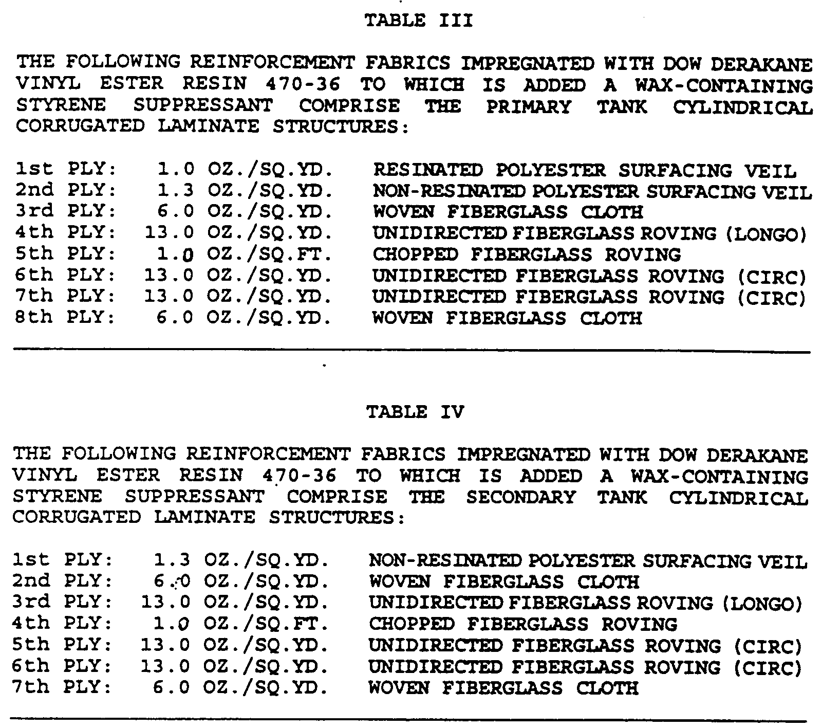
- The construction of the
primary container 6 onto thetank frame structure 2 prior to fabricating thesecondary container 7 will now be described. The cylindrical composite laminate shell structure forming theprimary container 6 is disposed on a plurality of uniformly spaced metalannular ribs 12 of thetank frame 2, and includes a plurality ofplies 6a-6h. While eightplies 6a-6h are shown for illustration purpose, it should be understood that additional plies can be used, without departing from the scope of the invention. Afirst ply fabric 6a preferably includes a stiff apertured resinated polyester surfacing veil having a dry weight of 1 ounce per square yard (34 gm/sq.m),a thickness of approximately 0.010 inch (0.25 mm), and a width in the range of 36 inches to 72 inches (91.4 cm to 183 cm). The warp threads of the first ply fabric extend generally in the direction of the longitudinal tank frame axis. - A
second ply fabric 6b preferably includes a soft apertured polyester surfacing veil having a dry weight of 1.3 ounce per square yard (44 gm/sq.m) and a thickness of approximately 0.010 inch (0.25 mm), and a width in the range 18 inches to 48 inches. The warp threads of thesecond ply fabric 6b are disposed transversely to and superimposed over the warp threads of thefirst ply fabric 6a to impose a substantially uniform load thereon, in order to deflect the first andsecond plies third ply fabric 6c is preferably made of woven fiberglass cloth having a tensile strength equal to 200 lb per inch (3.543 kg/mm)of width, a dry weight of 6 ounce per square yard (204 gm/sq.m), a thickness of 0.010 inch (0.25 mm), and a width in the range of 12 inches to 52 inches (30.4 cm to 132 cm). The warp threads of thethird ply fabric 6c are disposed approximately parallel to the warp threads of thesecond ply 6b upon which thethird ply 6c is superimposed. Afourth ply fabric 6d of unidirected continuous glass filament strands extend generally parallel to the longitudinal cylindrical axis, and has a tensile strength equal to 1200 lb. per inch (21 kg/mm) of width, a dry weight of 13 ounce per square yard (442 gm/sq.m), a thickness of 0.03 inch (0.80 mm), and a width in the range of 36 inches to 72 inches (91.4 cm to 183 cm) - A
fifth ply fabric 6e preferably includes randomly oriented chopped fiberglass strands having a dry weight of approximately 1 ounce per square foot (305 gm/sq.m),a thickness of approximately 0.010 inch (0.25 mm), and a width in the range of 36 inches to 72 inches (91.4 cm to 183 cm). A sixth ply 6f generally includes a warp of unidirected circumferentially oriented continuous glass filament strands disposed transversely to and superimposed over the fourth plyglass filament strands 6d to impose a substantially uniform load thereon. The sixth ply warp 6f has a tensile strength equal to 1200 lb. per inch (21 kg/mm) of width, a dry weight of 13 ounce per square yard (442 gm/sq.m), a thickness of 0.03 inch (0.08 mm), and a width in the range of 4 to 60 inches (10 to 150 cm). - A seventh ply 6g preferably includes a warp of unidirected continuous glass filament strands, superimposed upon and disposed approximately parallel to the sixth ply glass filament strands 6f, and has a tensile strength equal to 1200 lb. per inch (21 kg/mm) of width, a dry weight of 13 ounce per square yard (442 gm/sq.m), a thickness of 0.03 inch (0.08 mm), and a width in the range of 4 to 60 inches (10 to 150 cm). An
eighth ply fabric 6h is preferably made of woven fiberglass cloth having a tensile strength equal to 200 lb per inch (3.543 kg/mm)of width, a dry weight of 6 ounce per square yard (204 gm/sq.m) and a thickness of 0.010 inch (0.25 mm). - The construction of the
secondary container 7 onto theprimary container 6 will now be described. A plastic annulus-formingsheet 22 is used to completely enclose and cover the cylindrical compositelaminate shell structure 6h of theprimary container 6, except for the tankoutlet laminate regions 19, as illustrated in Figs 2 and 3, where the primary and secondary cylindrical laminates are bonded together. Anannulus space 23 between the primary and secondary cylindrical compositelaminate tank shells 5, formed by theintermediate plastic sheet 22, is preferably less than 0.06 inches(1.5 mm) to enable the outersecondary tank shell 7 to protect as well as to structurally reinforce the innerprimary tank shell 6, when the double-wall tank 1 is subjected to shipping and handling impacts and to tank shell stresses resulting from internal pressure or installation-produced compression loads. - Except for the
first ply fabric 6a, the cylindrical composite laminate shell structure forming thesecondary container 7 is preferably made of the same materials as the composite laminate shell structure forming theprimary container 6, and in the same sequence. Afirst ply fabric 7a comprises a soft apertured polyester surfacing veil. Asecond ply fabric 7b is made of woven fiberglass cloth. A third ply fabric 7c includes unidirected longitudinally oriented filament strands. Afourth ply fabric 7d includes chopped fiberglass strands. Afifth ply 7e andsixth ply 7f include circumferentially oriented continuous glass filament strands. A seventh outer ply 7g comprises woven fiberglass cloth. The individual laminate plies forming the cylindrical laminate structure of theprimary container 6 andsecondary container 7 are impregnated with a hardenable liquid vinyl ester resin matrix containing from 30 to 40% styrene monomer to which is added 1.3 percent by weight a liquid wax-containing styrene suppressant. The preferred matrix material is made by Dow USA and identified as Derakane 470-36. - Fig. 1 illustrates the preferred form of the
metal tank frame 2 which includes a generally cylindrical laminate-formingmetal mandrel structure 9 connected to hemispherical-shaped metalskeleton end structures 10 that provide the tank frame with axle supports 11 (Fig. 6) that enable the tank frame to be rotated while supported at the frame extremities by a tank frame turning unit (not shown). The cylindricaltank frame structure 9 is made from uniformly spacedannular metal ribs 12 supported by ninemetal longerons 13 having ends connected to the hemispherical-shaped metal tank ends 10 that accept removable threaded axles (not shown) connected to a powered tank frame turning unit. - The preferred frame outside diameter is 95 inches (241 cm). The preferred material from which to construct the
tank frame ribs 12, theframe longerons 13 and each of the hemisphericalend support structures 10 iscarbon steel channel 14 shown in Fig. 9 having a cross section area of approximately 0.5 square inches (3.23 sq.cm), a channel material thickness of approximately 0.125 inches (.32 cm), a channel flange height of 1.0 inches (2.54 cm), and a channel web width of 2.0 inches (5.08 cm). - When the
tank frame ribs 12 are made fromsteel channel 14 spaced 12 inches apart, they will provide thetank frame structure 2 with a compression strength and buckle-resistant stiffness (proportional to the moment of inertia, I , of the cross sectional area) that is twice as great as that of a UL listed steel tank structure (U.L. subject 1316), and do so with one-sixth the weight of the steel tank. Thesteel channel 14 shown in Fig. 9 has a moment of inertia, I, equal to 0.0362 in⁴ and cross sectional area equal to 0.04576 in². By comparison, the moment of inertia of a 12 inchlong steel plate 1/4 inch thick, typical ofSubject 58 tanks, is equal to .0156 in⁴ and a cross sectional area is equal to 3 square inches. - As shown in Figs. 3 and 7, each
outlet fitting plate 15 is welded to thetank frame 2 and is flush with the tank frame rib cylindrical outer surface and located on the uppermost portion of the tank frame between the tank frame ribs. Eachoutlet fitting plate 15 is made from a curved steel plate welded to the outer edges of adjacent tank frame ribs. The outletfitting plates 15 contain openings 16 (Fig. 3) that provide access to the tank interior viapipe outlet fittings 17. Each of the outletfitting plates 15 is constructed to have at least 100 square inches of perimeter surface 18 to which theinterior outlet region 19 of the primary container laminate surface can be bonded and sealed. - Fig. 7 illustrates a preferred embodiment of a composite double-wall tank fitting
outlet structure 20 includingnon-corrugated outlet regions 21 of thecylindrical laminate structures 5 bonded together and sandwiched between two curved metal outlet plates and sealed with an overlappinglaminate structure 27. The interior curvedmetal fitting plate 15, containing at least one outlet fitting 17, is welded to adjacent tank frameannular ribs 12 made of steel channel material to provide an outerfitting plate surface 24 that is flush with the exterior edge of the tank frame rib. - The interior surface of the tank outlet regions of the primary
tank laminate structure 19 is bonded to metal fitting plate surfaces 24 with the thermosetting resin matrix used to impregnate the laminate ply reinforcements of theprimary container 6. The exterior laminate surface of the primarytank outlet regions 19 is likewise bonded to the interior laminate surface of the secondarytank outlet regions 25. The laminate outlet regions bonded to the tankoutlet fitting plate 15 and to each other have a bonding surface area at least equal in area to that of the metal fitting plate surface. An outer curved metal tankoutlet compression plate 26 is bolted to the interiormetal outlet plate 15, and surmounts and is bonded to the exterior surface of the secondarylaminate outlet region 25. The exterior surface edges surrounding the outlet opening of the boltedmetal compression plate 26 is covered by an outletlaminate sealing structure 27 that overlaps the surface edges and is bonded to a width of the exterior surface of the secondary tank outlet region surrounding thecompression plate 26. - Fig. 4 illustrates a preferred embodiment of the double-wall
underground storage tank 1 having tank support saddles 28 that elevate the tank bottom above atank support surface 29 to prevent damage to theannulus sump 30 and facilitate inspection of thetank bottom 31. - Fig. 5 illustrates a preferred
annulus access structure 32 comprising a secondary container hemisphericallaminate tank end 4 configured to provide an annulussump access conduit 33 that enables a flexible dip stick or leak detectingsensor system 34 to monitor the tank's containment integrity. The upper end of the composite annulus access structure contains a threaded-end metal pipe. Thetank support saddle 28 comprises a multiple ply composite laminate structure having a wall thickness of approximately 0.25 inches (6 mm) and bonded to the bottom outer tank surface to provide a foot print measuring approximately 6 inches by 48 inches. - Fig. 6. shows a preferred frame support axle access including composite head seal laminates 38 and 39 used to seal a primary tank
axle access hole 36 as well as a secondarytank access hole 37. Theholes axle support structure 11. The primary tankhemispherical end 4 comprises a 5 inchdiameter axle hole 36 sealed by a five ply headseal laminate structure 38 having a diameter of approximately 10 inches. Thelaminate structure 38 comprises a first ply of 1.5 oz./sq. ft. fiberglass mat, a second ply of 18 oz/sq.yd. woven fiberglass roving, a third ply of fiberglass mat, a fourth ply of woven roving and a fifth ply of 6 oz/sq. yd. woven fiberglass fabric. A secondary tankhemispherical end 7h comprises a 14 inchdiameter axle hole 37 and a 14 inch diameter circular headclosure laminate structure 7k that may include a portion of the annulussump access conduit 33. The secondarytank access hole 37 is sealed by a five ply annular headseal laminate structure 39 having an inside diameter of 10 inches and an outer diameter of 18 inches, and is composed of the same materials as the primary tankhead seal laminate 38. Aconduit pipe laminate 40 includes a similar 5 ply laminate construction, and is used to attach a metal annulus access pipe 41 to the annulussump access conduit 33. - Fig. 4 shows the preferred embodiment of a composite head to shell
anchor ring structure 42, which is a filament wound around an end extremity of eachhemispherical tank end 4, to anchor the longitudinalcontinuous filament strands 6d forming the 4th ply of the primary tank shell cylindrical corrugated laminate to the outer ply 4e of the primary hemispherical tank end laminate, and the 3rd ply of the secondary tank shell cylindrical laminate 7c to the outer ply 4e of the secondary hemisphericaltank end laminate 7h. The primary tank head to shell anchor ring is preferably composed of the circumferentially oriented continuous filament strands comprising the beginning and ending winding of the sixth and seventh primary tank circ plies 6f and 6g. The secondary tank head to shell anchor ring is preferably composed of the circumferentially oriented continuous filament strands forming the beginning and ending winding of the fifth and sixth secondary tank circ plies 7e and 7f. - The following steps describe a preferred method and apparatus for making the preferred embodiment illustrated in Fig. 1. The preferred method and apparatus described below were used to make an eight foot diameter 12,000 gallon size double-wall non-metallic underground tank tested by Underwriters Laboratories, Inc. August 5, 1993 to demonstrate that the tank fully complies with the requirements of UL 1316 Type II Class 16.
- The preferred method for making a desired form of composite double-wall underground tank comprises the steps of:
cutting channel-shapedsteel 14 from 30 foot long stock to the lengths required to make an integral tank mandrel andhead support structure 10 from 8 foot diametersteel frame ribs 12,frame longerons 13 and head formers;
shaping annular ribs and hemispherical frame head forming members in a ring-rolling unit;
fabricating in a welding jig theannular ribs 12 andlongerons 13 into cylindrical tank frame sections having ribs spaced 12 inches apart and lengths of either 4.5 ft. or 5.5 feet;
fabricating the hemi-head members in a welding jig to make the hemisphericalframe end sections 10 and frameaxle support structure 11;
assembling thetank frame cylinder 9 from cylindrical tank frame sections andhemispherical head sections 10 to make an axle-supportedtank mandrel 2;
forming steel fitting plate stock to have an outer surface radius equal to that of the tank frame ring outer radius;
cutting tank outlets from the curved fitting plate stock and trimming so fitting plates will fit between tank frame rings;
weldingsteel half couplers 17 to the inner surface of tank outletfitting plates 15;
welding the tank outletfitting plates 15 to the perimeter edge oftank frame ribs 12 bordering each fitting plate;
welding strike plates beneath all tank outlet fitting plates;
making first hemispherical composite laminate tanks ends 4 from a five-ply sequence of overlapping trapezoidal-shaped fabrics impregnated with a thermosetting plastic and fabricated upon hemispherical tank end molds;
attaching prefabricated first hemispherical composite laminate tank ends 4 upon the hemispherical frame end-support structure 10 of the completedtank frame mandrel 2;
mounting the tank end andframe assembly 2 upon a motorized tank frame turning unit;
grinding theexternal surface 24 of each tankoutlet fitting plate 15 to produce a clean "white metal" surface;
bonding a three ply layer of resin-impregnatedpolyester surfacing veil 6a to the freshly ground surface of each tankoutlet fitting plate 15;
cutting to length and bonding to the perimeter edge of each hemispherical compositelaminate tank end 4 a 9 inch wide overlapping end portion of individual widths of dry stiff resinated aperturedpolyester surfacing veil 6a that is stretched as a taut fabric to cover the spacedtank frame ribs 12;
impregnating with a liquid thermosetting resin a warp of soft non-resinated aperturedpolyester surfacing veil 6b dispensed from a fabric-roll coater;
helically wrapping, from one tank end to the other, a resin-wet warp ofpolyester surfacing veil 6b upon the dry tautpolyester veil fabric 6a;
impregnating and deflecting the drytaut fabric 6a between thetank frame ribs 12 to produce a corrugated resin-wet two-ply laminate surface;
covering the corrugated wet laminate surface with a sequence of parallel widths of dry tightly woven 6 ounce per squareyard fiberglass cloth 6c;
pressing thedry fiberglass cloth 6c to intimately contact the corrugated resin-wet two-ply laminate surface;
impregnating theglass cloth fabric 6c with a liquid thermosetting resin to produce a three-ply liner laminate structure;
attaching to each tank end 4 a 9 inch overlapping edge of a width of dry unidirectedlongo ply fabric 6d comprising continuous strands of glass fiber oriented parallel to the tank frame axis and having an outer surface consisting of a mat layer of chopped fiberglass roving 6e;
placing additional similarly-attached parallel widths of dry unidirected longo ply fabrics upon the corrugated three-ply liner laminate surface that completely encloses thetank frame 2;
impregnating with a liquid thermosetting polymeric resin matrix a warp of unidirected circ ply fabric 6f comprising continuous strands of glass fiber;
attaching the leading edge of the circ ply fabric 6f to one of the drylongo ply fabrics 6d bonded to afirst tank end 4 so that an edge of the circ ply warp 6f overlaps, by approximately 9 inches, the edge extremity of a primary hemispherical compositelaminate tank end 4;
making a single circumferentially-oriented wrap of the resin-wet circ ply warp 6f upon the dry end-bondedlongo ply fabric 6d to provide a first head-to-shell anchor ring 42;
helically winding a first edge-abutting sequence of resin-wet circ ply warps 6f to press upon and impregnate the drylongo ply fabric 6d from a first tank end to a second tank end;
winding two circumferential wraps of the matrix-impregnated circ ply fabric 6g upon thedry longo ply 6d andglass mat fabrics 6c overlapping the edge extremity of a second primary hemisphericalhead end 4 to provide a second shell-to-head anchor ring 42;
helically winding, from a first tank end to a second tank end, a second edge-abutting sequence of resin-wet circ ply warps 6g;
wrapping a single cover ply of dry tightly woven 6 ounce per squareyard fiberglass cloth 6h upon the wet plies of circ fabric 6g;
inspecting the tank outlet fitting plate surfaces 24 to assure that the resin-impregnated inner tank laminate plies 6a are in void-free intimate contact with the tank outlet fitting plate surfaces 24;
painting theprimary tank 6 shell exterior surface with an opaque thermosetting resin;
curing the primary tank shell laminate matrix and cover ply resins;
covering completely the primary tank cylindrical composite laminate structure with an opaque 6 mil thickpolyethylene plastic sheet 22 that overlaps a 12 inch wide extremity of each primary hemispherical compositelaminate tank end 4;
cutting and removing theplastic sheet 22 around the tankoutlet fitting plate 15 bonding areas;
removing theprimary tank 6 from the turning support unit;
making second hemispherical composite laminate tanks ends 4 from a six-ply sequence of overlapping trapezoidal-shaped fabrics impregnated with a thermosetting plastic and fabricated upon hemispherical tank end molds, wherein one of said tank end molds is configured to provide a hemispherical composite laminate tank end having anintegral annulus access 32 andbottom sump structure 30;
placing the prefabricated second hemispherical composite laminate tank ends 7h upon the prefabricated primary tank first hemispherical composite laminate tank ends 4;
mounting the primary tank and second tank ends upon a motorized tank frame turning unit;
grinding the exterior surface of the primary tank shell laminate in thoseregions 19 where it is bonded to the underlying tank metaloutlet fitting plates 15;
making the secondary cylindrical composite laminate tank shell structure 7g by repeating the same procedures with the same materials as those used to make the primary cylindrical composite laminatetank shell structure 6h;
cutting tank outlet holes 16 through primary and secondary cylindrical composite laminate structures at all tank fitting outlet locations;
boltingmetal compression plates 26 to all metaloutlet fitting plates 15;
placing a three-ply laminate 27 to overlap and cover the edges of all boltedmetal compression plates 26 to seal all tank outlet fittings;
installing a lift lug in a central tank outlet fitting 17;
lifting and removing the completed double wall tank structure from the mandrel turning support unit;
laminating a composite seal to cover theaxle access openings
leak testing the primary andsecondary containers - While the preferred and other embodiments have been described above, it should be understood that other embodiments are also contemplated within the scope and spirit of the present invention.
- The composite double-wall underground tank according to the present invention is a substantial improvement over conventional steel and fiberglass tanks, and provides a more reliable method of protecting the environment by preventing the release of contaminating hazardous liquids stored in the tank. In particular, the metal tank frame structure provides the buckling resistance and compression strength to resist soil loads when the tank is buried.
Claims (35)
- A multiple wall tank structure comprising in combination:
a metal frame having at least one outlet fitting plate;
an impermeable non-metallic primary container including a chemically resistant multiple-ply laminate structure surmounting and at least partially enclosing said metal frame;
said primary container including at least one primary outlet panel disposed in registration with, and bonded to at least one outlet fitting plate;
an impermeable non-metallic secondary container including a chemically resistant multiple-ply laminate structure surmounting and at least partially enclosing said primary container;
said secondary container including at least one corresponding secondary outlet panel disposed in registration with, and bonded to at least one primary outlet panel; and
at least one said outlet fitting plate, at least one said primary outlet panel and at least one said corresponding secondary outlet panel forming at least one pressure-resistant outlet seal. - The multiple wall tank structure according to claim 1 wherein
said primary and secondary containers include a space therebetween; and
said secondary container is provided with an annulus access conduit opening for enabling said space between said primary and secondary containers to be connected by said conduit to the atmospheric pressure. - The multiple wall tank structure according to claim 2 wherein said metal frame includes at least one end; and
wherein said at least one end has a generally hemispherical configuration. - The multiple wall tank structure according to claim 3 wherein said metal frame is elongated and extends longitudinally along a geometric axis;
wherein said geometric axis is disposed substantially horizontally; and
wherein at least one said outlet fitting plate is located on an uppermost surface of said metal frame. - The multiple wall tank structure according to claim 4 wherein said metal frame includes a plurality of spaced metal annular ribs that are coaxially positioned relative to said axis;
wherein said plurality of annular ribs are attached to a plurality of circumferentially spaced metal longerons; and
wherein at least one said outlet fitting plate is secured to adjacent ones of said plurality of annular ribs and longerons. - The multiple wall tank structure according to claim 5 wherein at least one said outlet fitting plate is flush with said adjacent ones of said annular ribs to which it is secured.
- The multiple wall tank structure according to claim 6 wherein at least one end of said metal frame includes a plurality of curved metal ribs that are secured to one of said annular ribs and to a frame support axle fitting.
- The multiple wall tank structure according to claim 7 wherein at least some of said annular ribs and at least some of said longerons have a channel shaped cross- section.
- The multiple wall tank structure according to claim 8 wherein said plurality of annular ribs and said plurality of curved ribs have a generally similar shape and cross section.
- The multiple wall tank structure according to claim 9 wherein said metal frame is made from carbon steel.
- The multiple wall tank structure according to claim 10 wherein said plurality of annular and curved ribs and said plurality of longerons are made of steel channels having a web width of about 2 inches, a flange height of about 1 inch and a web thickness in the range of 0.125 and 0.1875 inches.
- The multiple wall tank structure according to claim 11 wherein said plurality of annular ribs are uniformly spaced apart along said geometric axis of said frame by a distance approximately equal to 12 inches and are fabricated with flanges facing outwardly to have a maximum outside diameter in the range of 95 to 119 inches.
- The multiple wall tank structure according to claim 12 wherein said plurality of longerons includes nine longerons;
wherein one longeron is a bottom longeron, and includes flanges facing down;
wherein three adjacent side longerons are spaced apart by about 45 degrees, and include flanges facing toward the bottom;
wherein two uppermost longerons are secured to said plurality of annular ribs, and include flanges that face away from a vertical plane passing through said longitudinal geometric axis, and which are spaced apart by a distance ranging between 9 and 12 inches. - The multiple wall tank structure according to claim 7 wherein said frame support axle fitting includes a generally circular steel plate to which is welded a steel half coupler suitable to be removably connected to a frame support axle.
- The multiple wall tank structure according to claim 14 wherein said metal frame includes two oppositely disposed generally hemispherical ends.
- The multiple wall tank structure according to claim 15 wherein each of said ends includes between 3 and 50 curved ribs made from different lengths of steel channels and having ends secured to said support axle fitting and an annular rib made from a rolled steel channel.
- The multiple wall tank structure according to claim 2 wherein said primary container includes two generally hemispherically shaped composite laminate ends that are bonded and sealed within corresponding ends of a corrugated first cylindrical composite laminate shell structure; and
wherein said secondary container includes two generally hemispherically shaped composite laminate ends that are bonded and sealed within corresponding ends of a corrugated second cylindrical composite laminate shell structure. - The multiple wall tank structure according to claim 17 wherein said metal frame includes a plurality of spaced metal annular ribs;
wherein said metal frame is elongated and extends longitudinally along a geometric axis; and
wherein said first cylindrical composite laminate shell structure includes a multiple ply reinforced plastic laminate structure disposed on said annular ribs comprising:
a first ply fabric including a stiff apertured resinated polyester surfacing veil having warp threads;
a second ply fabric including a soft apertured polyester surfacing veil having warp threads, such that said warp threads of said second ply fabric are disposed generally transversely to and superimposed over said warp threads of said first ply to impose a substantially uniform load thereon, and to deflect said first and second plies into a plurality of corrugations;
a third ply fabric of woven fiberglass cloth having warp threads, such that said warp threads of said third ply fabric are disposed in a substantially parallel relationship to said warp threads of said second ply upon which said third ply is disposed;
a fourth ply fabric of unidirected continuous first glass filament strands extending substantially parallel to said geometric axis;
a fifth ply fabric including randomly oriented chopped fiberglass strands;
a sixth ply fabric including a warp of unidirected continuous second glass filament strands disposed transversely to and superimposed over said first glass filament strands to impose a substantially uniform load thereon;
a seventh ply comprising a warp of unidirected continuous third glass filament strands, superimposed upon and disposed approximately parallel to said second glass filament strands;
an eighth ply fabric of woven fiberglass cloth; and
a hardenable liquid vinyl ester resin for impregnating the filament reinforcements contained in said laminate structure. - The multiple wall tank structure according to claim 17 wherein said metal frame is elongated and extends longitudinally along a geometric axis; and
wherein said first hemispherical composite laminate end includes:
a first ply formed of a soft apertured polyester surfacing veil;
a second ply comprising a plurality of unidirected filament fabric having a warp of continuous filament strands positioned so that said filament strands are substantially perpendicular to said geometric axis;
a third ply formed of a fabric of chopped strand fiberglass;
a fourth ply formed of a fabric of woven fiberglass roving;
a fifth ply formed of woven fiberglass cloth; and
a hardenable liquid vinyl ester resin for impregnating the fabric filament reinforcements contained in said laminate structure. - The multiple wall tank structure according to claim 17 wherein said metal frame is elongated and extends longitudinally along a geometric axis; and
wherein said second cylindrical composite laminate shell structure comprises a corrugated multiple ply reinforced plastic laminate structure and including:
a first ply fabric formed of a soft apertured polyester surfacing veil and having warp threads;
a second ply fabric formed of woven fiberglass cloth and having warp threads, such that said warp threads of said second ply fabric are disposed generally transversely to and superimposed over said warp threads of said first ply, to impose a substantially uniform load thereon, and to deflect said first and second plies into a plurality of corrugations
a third ply fabric formed of unidirected continuous first glass filament strands extending substantially parallel to said geometric axis and having warp threads, such that said warp threads of said third ply fabric are disposed substantially in a parallel relationship relative to said warp threads of said second ply upon which said third ply is superimposed;
a fourth ply fabric including randomly oriented chopped fiberglass strands;
a fifth ply including a warp of unidirected continuous second glass filament strands disposed generally transversely to and superimposed over said first glass filament strands to impose a substantially uniform load thereon;
a sixth ply including a warp of unidirected continuous third glass filament strands, superimposed upon and disposed generally parallel to said second glass filament strands;
an seventh ply fabric of woven fiberglass cloth; and
a hardenable liquid vinyl ester resin for impregnating the filament reinforcements contained in said laminate structure. - The multiple wall tank structure according to claim 17 wherein said metal frame is elongated and extends longitudinally along a geometric axis; and
wherein said second hemispherical composite laminate end includes a multiple ply reinforced plastic laminate structure comprising:
a first ply formed of a soft apertured polyester surfacing veil;
a second ply comprising a plurality of unidirected filament fabric having a warp of continuous filament strands positioned so that said filament strands are substantially parallel to said geometric axis;
a third ply formed of a fabric of chopped strand fiberglass;
a fourth ply formed of a fabric of woven fiberglass roving;
a fifth ply formed of woven fiberglass cloth; and
a hardenable liquid vinyl ester resin for impregnating the fabric filament reinforcements contained in said laminate structure. - The multiple wall tank structure according to claim 17 wherein one end of said second cylindrical composite laminate structure is configured to provide a bottom liquid sump container;
wherein said sump container is connected to a bottom end of a curved tubularly-shaped centrally positioned conduit structure forming a lower quarter section of one of said second hemispherical composite laminate tank ends to provide an annulus access structure that connects an open upper end of said conduit structure with said sump container. - The multiple wall tank structure according to claim 22 wherein at least two saddle support structures are attached to said second cylindrical composite laminate structure so as to elevate the bottom of said sump container above the surface upon which the tank structure is placed.
- The multiple wall tank structure according to claim 23 wherein each of said saddle support structures includes a multiple ply composite laminate structure and is bonded to the bottom of the outer tank surface.
- The multiple wall tank structure according to claim 1 wherein said primary outlet panel includes openings that enclose said tank outlet fittings;
wherein said secondary outlet panels have openings that coincide and mate with the openings in said primary outlet panels; and
wherein said primary outlet panels have an inner surface that is bonded to the exterior surface of each of said fitting plates and said secondary outlet panels have an inner surface that is bonded to the exterior surface of each of said first outlet panels to form said pressure-resistant outlet seal. - The multiple wall tank structure according to claim 25 wherein
said primary outlet panel comprises a contiguous section of said first cylindrical composite laminate structure, and said secondary outlet panel comprises a contiguous section of said second cylindrical composite laminate structure. - The multiple wall tank structure according to claim 26 wherein said secondary outlet panel further includes a metal outlet compression plate having the same dimensions, openings and shape as said metal tank outlet plate; and
compression plate sealing means comprising an overlapping outer composite laminate structure having an outlet fitting opening and a perimeter border extending beyond the perimeter of said metal outlet compression plate, and the inner surface of said perimeter border is bonded to the exterior surface of said secondary tank shell outlet panel to provide a pressure resistant seal therewith. - The multiple wall tank structure according to claim 2 wherein the multiple wall tank structure is a double-wall underground storage tank
- The multiple wall tank structure according to claim 1 wherein
said multiple-ply laminate structures are corrugated. - The multipie wall tank structure according to claim 29 wherein
said corrugated multiple-ply laminate structures contain unchopped strands of continuous glass filaments impregnated with a low-styrene vinyl ester thermosetting resin containing a styrene suppressant to reduce emission of volatile aromatic compounds. - A method for fabricating a multiple wall tank structure comprising the steps of:
forming a metal frame with at least one outlet fitting plate;
surmounting said metal frame, at least partially by surmounting it with an impermeable non-metallic primary container including a chemically resistant multiple-ply laminate structure, said primary container including at least one primary outlet panel disposed in registration with, and bonded to said at least one outlet fitting plate;
surmounting said primary container, at least partially, with an impermeable non-metallic secondary container including a chemically resistant multiple-ply laminate structure, said secondary container including at least one secondary outlet panel disposed in registration with, and bonded to said at least one at least one primary outlet panel, whereby said at least one outlet fitting plate, said at least one primary outlet panel and said at least one secondary outlet panel forming a corresponding at least one pressure-resistant outlet seal;
forming a space between said primary and secondary containers; and
providing said secondary container with an annulus access conduit opening for enabling said space between said primary and secondary containers to be connected by said conduit to the atmospheric pressure. - A method for making a composite double-wall underground tank comprising the steps of:
cutting channel-shaped steel from 30 foot long stock to the lengths required to make 8 foot diameter steel frame ribs, frame longerons and head formers into an integral tank mandrel and head support structure,
shaping annular ribs and hemispherical frame head forming members in a ring-rolling unit,
fabricating in a welding jig the annular ribs and longerons into cylindrical tank frame sections having ribs spaced 12 inches apart and lengths of either 4.5 ft. or 5.5 feet,
fabricating the hemi-head members in a welding jig to make the hemispherical frame end sections and frame support axles,
assembling the a tank frame cylinder from cylindrical tank frame sections and hemispherical head sections to make an axle-supported tank mandrel,
forming steel fitting plate stock to have an outer surface radius equal to that of the tank frame ring outer radius,
cutting tank outlets from the curved fitting plate stock and trimming so fitting plates will fit between tank frame rings,
welding steel half couplers to the inner surface of tank outlet fitting plates,
welding the tank outlet fitting plates to the perimeter edge of tank frame rings bordering each fitting plate,
welding strike plates beneath all tank outlet fitting plates,
making first hemispherical composite laminate tanks ends from a six-ply sequence of overlapping trapezoidal-shaped fabrics impregnated with a thermosetting plastic and fabricated upon hemispherical tank end molds,
attaching prefabricated first hemispherical composite laminate tank ends upon the hemispherical frame end-support structure of the completed tank frame mandrel,
mounting the tank end and frame assembly upon a motorized tank frame turning unit,
grinding the external surface of each tank outlet fitting plate to produce a clean "white metal" surface,
bonding a three ply layer of resin-impregnated polyester surfacing veil to the freshly ground surface of each tank outlet fitting plate,
cutting to length and bonding to the perimeter edge of each hemispherical composite laminate tank end a 9 inch wide overlapping end portion of individual widths of dry stiff resinated apertured polyester surfacing veil that is stretched as a taut fabric to cover the spaced tank frame ribs,
impregnating with a liquid thermosetting resin a warp of soft non-resinated apertured polyester surfacing veil dispensed from a fabric-roll coater,
helically wrapping, from one tank end to the other, a resin-wet warp of polyester surfacing veil upon the dry taut polyester veil fabric,
impregnating and deflecting the dry taut fabric between the tank frame ribs to produce a corrugated resin-wet two-ply laminate surface,
covering the corrugated wet laminate surface with a sequence of parallel widths of dry tightly woven 6 ounce per square yard fiberglass cloth,
pressing the dry fiberglass cloth to intimately contact the corrugated resin-wet two-ply laminate surface,
impregnating the glass cloth fabric with a liquid thermosetting resin to produce a three-ply liner laminate structure,
attaching to each tank end a 9 inch overlapping edge of a width of dry unidirected long ply fabric comprising continuous strands of glass fiber oriented parallel to the tank frame axis and having an outer surface consisting of a mat layer of chopped fiberglass roving,
placing additional similarly-attached parallel widths of dry unidirected long ply fabrics upon the corrugated three-ply liner laminate surface that completely encloses the tank frame,
impregnating with a liquid thermosetting polymeric resin matrix a warp of unidirected circ ply fabric comprising continuous strands of glass fiber,
attaching the leading edge of the circ ply fabric to one of the dry long ply fabrics bonded to a first tank end so that an edge of the circ ply warp overlaps, by approximately 9 inches, the edge extremity of a primary hemispherical composite laminate tank end,
making a single circumferentially-oriented wrap of the resin-wet circ ply warp upon the dry end-bonded long ply fabric to provide a first shell-to-head anchor ring,
helically winding a first edge-abutting sequence of resin-wet circ ply warps to press upon and impregnate the dry long ply fabric from a first tank end to a second tank end,
winding two circumferential wraps of the matrix-impregnated circ ply fabric upon the dry long ply and glass mat fabrics overlapping the edge extremity of a second primary hemispherical head end to provide a second shell-to-head anchor ring,
helically winding, from a first tank end to a second tank end, a second edge-abutting sequence of resin-wet circ ply warps,
wrapping a single cover ply of dry tightly woven 6 ounce per square yard fiberglass cloth upon the wet plies of circ fabric,
inspecting the tank outlet fitting plate surfaces to assure that the resin-impregnated inner tank laminate plies are in void-free intimate contact with the tank outlet fitting plate surfaces,
painting the tank shell exterior surface with an opaque thermosetting resin,
curing the primary tank shell laminate matrix and cover ply resins,
covering completely the primary tank cylindrical composite laminate structure with an opaque 6 mil thick polyethylene plastic sheet that overlaps a 12 inch wide extremity of each primary hemispherical composite laminate tank end,
cutting and removing the plastic sheet around the tank outlet fitting plate bonding areas,
removing the primary tank from the turning support unit,
making second hemispherical composite laminate tanks ends from a six-ply sequence of overlapping trapezoidal-shaped fabrics impregnated with a thermosetting plastic and fabricated upon hemispherical tank end molds, wherein one of said tank end molds is configured to provide a hemispherical composite laminate tank end having an integral annulus access and bottom sump structure,
placing the prefabricated second hemispherical composite laminate tank ends upon the prefabricated primary tank first hemispherical composite laminate tank ends,
mounting the primary tank and second tank ends upon a motorized tank frame turning unit,
grinding the exterior surface of the primary tank shell laminate in those regions where it is bonded to the underlying tank metal outlet fitting plates,
making the secondary cylindrical composite laminate tank shell structure by repeating the same procedures with the same materials as those used to make the primary cylindrical composite laminate tank shell structure,
cutting tank outlet holes through primary and secondary cylindrical composite laminate structures at all tank fitting outlet locations,
bolting metal compression plates to all metal outlet fitting plates,
placing a three-ply laminate to overlap and cover the edges of all bolted metal compression plates to seal all tank outlet fittings,
installing a lift lug in a central tank outlet fitting,
lifting and removing the completed double wall tank structure from the mandrel turning support unit,
laminating a composite seal to cover the axle access openings in the primary and secondary composite hemispherical ends that provide the turning support unit with access to the steel frame axle fittings,
leak testing the primary and secondary containers by simultaneously pressurizing both containers to 5 psi. - The multiple wall tank structure according to claim 13 wherein said corrugated first cylindrical composite laminate shell structure comprises a multiple ply reinforced plastic laminate structure disposed on said uniformly spaced metal annular ribs along a horizontal longitudinal axis thereof comprising:
a first ply fabric comprising a stiff apertured resinated polyester surfacing veil having a dry weight of 1 ounce per square yard (34 gm/sq.m),a thickness of approximately 0.010 inch (0.25 mm), and a width in the range of 36 inches to 72 inches (91.4 cm to 183 cm), the warp threads of said first ply fabric extending generally in the direction of said axis;
a second ply fabric comprising a soft apertured polyester surfacing veil having a dry weight of 1.3 ounce per square yard (44 gm/sq.m) and a thickness of approximately 0.010 inch (0.25 mm), and a width in the range 18 inches to 48 inches, the warp threads of said second ply fabric disposed transversely of and superimposed over the warp threads of said first ply to impose a substantially uniform load thereon to deflect said first and second plies into a connected plurality of corrugations comprising a corrugated laminate having a generally concave parabolic portion formed between a pair of adjacent convex portions intersecting therewith, when viewed in cross section, relative to said axis:
a third ply fabric of woven fiberglass cloth having a tensile strength equal to 200 lb per inch (3.543 kg/mm)of width, a dry weight of 6 ounce per square yard (204 gm/sq.m), a thickness of 0.010 inch (0.25 mm), and a width in the range of 12 inches to 52 inches (30.4 cm to 132 cm), the warp threads of said third ply fabric disposed approximately parallel to the warp threads of said second ply upon which said third ply is superimposed;
a fourth ply fabric of unidirected continuous first glass filament strands extending parallel to said longitudinal cylindrical axis, said fabric having a tensile strength equal to 1200 lb. per inch (21 kg/mm) of width, a dry weight of 13 ounce per square yard (442 gm/sq.m), a thickness of 0.03 inch (0.80 mm), and a width in the range of 36 inches to 72 inches (91.4 cm to 183 cm);
a fifth ply fabric comprising randomly oriented chopped fiberglass strands having a dry weight of approximately 1 ounce per square foot (305 gm/sq.m), a thickness of approximately 0.010 inch (0.25 mm), and a width in the range of 36 inches to 72 inches (91.4 cm to 183 cm);
a sixth ply comprising a warp of unidirected continuous second glass filament strands disposed transversely of and superimposed over said first glass filament strands to impose a substantially uniform load thereon, said warp having a tensile strength equal to 1200 lb. per inch (21 kg/mm) of width, a dry weight of 13 ounce per square yard (442 gm/sq.m), a thickness of 0.03 inch (0.8 mm), and a width in the range of 4 to 60 inches (10 to 150 cm);
a seventh ply comprising a warp of unidirected continuous third glass filament strands, superimposed upon and disposed approximately parallel to said second glass filament strands, said warp having a tensile strength equal to 1200 lb. per inch (21 kg/mm) of width, a dry weight of 13 ounce per square yard (442 gm/sq.m), a thickness of 0.03 inch (0.8 mm), and a width in the range of 4 to 60 inches (10 to 150 cm);
an eighth ply fabric of woven fiberglass cloth having a tensile strength equal to 200 lb per inch (3.543 kg/mm)of width, a dry weight of 6 ounce per square yard (204 gm/sq.m) and a thickness of 0.010 inch (0.25 mm); and
a hardenable liquid vinyl ester resin, containing from 30 to 40 percent styrene monomer and 1.3 percent of a wax-containing styrene suppressant, impregnating the filament reinforcements contained in said laminate structure;
wherein said first hemispherical composite laminate structure comprises a multiple ply reinforced plastic laminate structure comprising:
a first ply comprising at least 15 overlapping trapezoidal-shaped fabrics cut from a soft apertured polyester surfacing veil having a dry weight of 1.3 ounce per square yard (44 gm/sq.m), a thickness of approximately 0.010 inch (0.25 mm), and a warp width in the range of 60 to 84 inches (1.5 to 2.1 m);
a second ply comprising at least three pieces of unidirected filament fabric having a warp of continuous filament strands positioned so said filament strands are approximately normal to said longitudinal cylindrical axis, said fabric having a tensile strength equal to 1200 lb. per inch (21 kg/mm) of width, a dry weight of 13 ounce per square yard (442 gm/sq.m), a thickness of 0.03 inch (0.80 mm), and a warp width in the range of 48 to 72 inches (1.2 to 1.8 m);
a third ply comprising at least 15 overlapping trapezoidal-shaped pieces cut from a fabric of chopped strand fiberglass having a dry weight of 1.5 ounce per square foot(458 gm/sq.m),a thickness of approximately 0.015 inch (0.38 mm),and a width in the range of 60 to 84 inches (1.5 to 2.1m);
a fourth ply comprising at least 15 overlapping trapezoidal-shaped pieces cut from a fabric of woven fiberglass roving , said fabric having a tensile strength equal to 600 lb. per inch (11 kg/mm) of width, a dry weight of 18 ounce per square yard (612 gm/sq.m), a thickness of 0.04 inch (1.00 mm) and a width in the range of 48 to 72 inches (1.2 to 1.8m);
a fifth ply comprising at least 15 overlapping trapezoidal-shaped fabrics cut from woven fiberglass cloth having a tensile strength equal to 200 lb per inch (3.543 kg/mm)of width, a dry weight of 6 ounce per square yard (204 gm/sq.m), a thickness of 0.010 inch (0.25 mm), and a warp width in the range of 60 to 84 inches (1.5 to 2.1 m); and
a hardenable liquid vinyl ester resin, containing from 30 to 40% styrene monomer to which is added 1.3 percent by weight a liquid wax-containing styrene suppressant, impregnating the fabric filament reinforcements contained in said laminate structure;
wherein each of said first hemispherical composite laminate tank ends is bonded and sealed to each end of said corrugated first cylindrical composite laminate shell structure with the first five of said fabric plies and wherein said tank ends are anchored to said shell structure by a shell-to-head anchor ring comprising the warp plies of said sixth and seventh ply fabrics surmounting and overlapping an end extremity of each of said first hemispherical composite laminate tank ends by an axial length in the range of 8 to 12 inches (20 to 30 cm);
wherein the axial distance of a first annulus space separating said first hemispherical composite laminate tank ends and said second hemispherical composite laminate tank ends is in the range of approximately 0.12 inches (3 mm)to 0.36 inches (9 mm);
wherein the vertical distance of a second annulus space separating the bottom half of said first cylindrical composite laminate structure from the bottom half of said second cylindrical composite laminate structure is in the range of approximately 0. 01 inches (0.25 mm) to 0.36 inches (9 mm);
wherein said second annulus space contains a sheet of plastic having a thickness in the range of 0.001 to 0.010 inches (0.025 to 0.25 mm), said plastic sheet superimposed upon and covering the entire surface of said first cylindrical composite laminate structure except those surfaces comprising said first outlet panels;
wherein said second cylindrical composite laminate shell structure comprises a corrugated multiple ply reinforced plastic laminate structure disposed on said plastic sheet comprising:
a first ply fabric comprising a soft apertured polyester surfacing veil having a dry weight of 1.3 ounce per square yard (44 gm/sq.m) and a thickness of approximately 0.010 inch (0.25 mm), and a width in the range 18 inches to 48 inches, said first ply fabric superimposed on said plastic sheet to impose a substantially uniform load thereon to produce a connected plurality of corrugations comprising a corrugated laminate having a generally concave parabolic portion formed between a pair of adjacent convex portions intersecting therewith, when viewed in cross section, relative to said axis;
a second ply fabric of woven fiberglass cloth having a tensile strength equal to 200 lb per inch (3.543 kg/mm)of width, a dry weight of 6 ounce per square yard (204 gm/sq.m), a thickness of 0.010 inch (0.25 mm), and a width in the range of 12 inches to 52 inches (30.4 - 132 cm), the warp threads of said second ply fabric disposed approximately parallel to the warp threads of said first ply upon which said second ply is superimposed;
a third ply fabric of unidirected continuous first glass filament strands extending parallel to said longitudinal cylindrical axis, said fabric having a tensile strength equal to 1200 lb. per inch (21 kg/mm) of width, a dry weight of 13 ounce per square yard (442 gm/sq.m), a thickness of 0.03 inch (0.80 mm), and a width in the range of 36 inches to 72 inches (91.4 - 183 cm);
a fourth ply fabric comprising randomly oriented chopped fiberglass strands having a dry weight of approximately 1 ounce per square foot (305 gm/sq.m),a thickness of approximately 0.010 inch (0.25 mm), and a width in the range of 36 inches to 72 inches (91.4 - 183 cm);
a fifth ply comprising a warp of unidirected continuous second glass filament strands disposed transversely of and superimposed over said first glass filament strands to impose a substantially uniform load thereon, said warp having a tensile strength equal to 1200 lb. per inch (21 kg/mm) of width, a dry weight of 13 ounce per square yard (442 gm/sq.m), a thickness of 0.03 inch (0.8 mm), and a width in the range of 4 to 60 inches (10 to 150 cm);
a sixth ply comprising a warp of unidirected continuous third glass filament strands, superimposed upon and disposed approximately parallel to said second glass filament strands, said warp having a tensile strength equal to 1200 lb. per inch (21 kg/mm) of width, a dry weight of 13 ounce per square yard (442 gm/sq.m), a thickness of 0.03 inch (0.8 mm), and a width in the range of 4 to 60 inches (10 to 150 cm);
an seventh ply fabric of woven fiberglass cloth having a tensile strength equal to 200 lb per inch (3.543 kg/mm)of width, a dry weight of 6 ounce per square yard (204 gm/sq.m) and a thickness of 0.010 inch (0.25 mm);
a hardenable liquid vinyl ester resin, containing from 30 to 40 percent styrene monomer and 1.3 percent of a wax-containing styrene suppressant, impregnating the filament reinforcements contained in said laminate structure;
wherein said second hemispherical composite laminate structure comprises a multiple ply reinforced plastic laminate structure comprising:
a first ply comprising at least 15 overlapping trapezoidal-shaped fabrics cut from a soft apertured polyester surfacing veil having a dry weight of 1.3 ounce per square yard (44 gm/sq.m), a thickness of approximately 0.010 inch (0.25 mm), and a warp width in the range of 60 to 84 inches (1.5 to 2.1 m);
a second ply comprising at least three pieces of unidirected filament fabric having a warp of continuous filament strands positioned so said filament strands are approximately normal to said longitudinal cylindrical axis, said fabric having a tensile strength equal to 1200 lb. per inch (21 kg/mm) of width, a dry weight of 13 ounce per square yard (442 gm/sq.m), a thickness of 0.03 inch (0.80 mm), and a warp width in the range of 48 to 72 inches (1.2 to 1.8 m);
a third ply comprising at least 15 overlapping trapezoidal-shaped pieces cut from a fabric of chopped strand fiberglass having a dry weight of 1.5 ounce per square foot(458 gm/sq.m),a thickness of approximately 0.015 inch (0.38 mm),and a width in the range of 60 to 84 inches (1.5 to 2.1m);
a fourth ply comprising at least 15 overlapping trapezoidal-shaped pieces cut from a fabric of woven fiberglass roving , said fabric having a tensile strength equal to 600 lb. per inch (11 kg/mm) of width, a dry weight of 18 ounce per square yard (612 gm/sq.m), a thickness of 0.04 inch (1.00 mm) and a width in the range of 48 to 72 inches (1.2 to 1.8m);
a fifth ply comprising at least 15 overlapping trapezoidal-shaped fabrics cut from woven fiberglass cloth having a tensile strength equal to 200 lb per inch (3.543 kg/mm)of width, a dry weight of 6 ounce per square yard (204 gm/sq.m), a thickness of 0.010 inch (0.25 mm), and a warp width in the range of 60 to 84 inches (1.5 to 2.1 m);
a hardenable liquid vinyl ester resin, containing from 30 to 40% styrene monomer to which is added 1.3 percent by weight a liquid wax-containing styrene suppressant, impregnating the fabric filament reinforcements contained in said laminate structure;
wherein each of said second hemispherical composite laminate tank ends is bonded and sealed to each end of said corrugated second cylindrical composite laminate shell structures with the first four of said fabric plies and wherein said tank ends are anchored to said shell structure by a shell-to-head anchor ring comprising the warp plies of said fifth and sixth ply fabrics surmounting and overlapping an end extremity of each of said second hemispherical composite laminate tank ends by an axial length in the range of 8 to 12 inches (20 to 30 cm);
wherein one end of said second cylindrical composite laminate structure is configured to provide a bottom liquid sump container, said sump container connected to the bottom end of a curved tubular-shaped centrally positioned conduit structure comprising the lower quarter section of one of said second hemispherical composite laminate tank ends to provide an annulus access structure that connects the open upper end of said conduit structure with said sump container;
wherein the open upper end of said annulus access structure is fitted with a 1 1/2 inch threaded pipe half coupler;
wherein two saddle tank support structures are attached to the bottom ends of said second cylindrical composite laminate structure so as to elevate the bottom of said sump container approximately 4 inches above the surface upon which said tank structure is placed;
wherein each of said saddle structures comprises a multiple ply composite laminate structure having a wall thickness of approximately 0.25 inches (6 mm) and bonded to the bottom outer tank surface to provide a foot print measuring approximately 6 inches by 48 inches;
wherein said first outlet panel comprises a contiguous section of said first cylindrical composite laminate structure and said second outlet panel of said secondary container comprises a contiguous section of said second cylindrical composite laminate structure;
wherein said second outlet panel further comprises a metal outlet compression plate having the same dimensions, openings and shape as said metal tank outlet plate, bolting means by which said outlet compression plate is connected to said metal tank outlet plate;
compression plate sealing means comprising an overlapping outer composite laminate structure having an outlet fitting opening and a perimeter border extending approximately 4 inches (10 cm) beyond the perimeter of said metal outlet compression plate, the inner surface of said 4 inch (10 cm) perimeter border bonded to the exterior surface of said second tank shell outlet panel to provide a pressure resistant seal therewith;
wherein said annular space separating said primary container from said secondary container is in the range of 0.010 and 0.375 inches (0.25 - 9.5 mm); and
wherein the minimum thickness of said multiple ply reinforced plastic laminate structure is in the range of 0.12 and 0.34 inches (3 - 8.6 mm). - The multiple wall tank structure according to claim 33 wherein a sand aggregate having a grain size in the range of 0.01 and 0.25 inches (0.25 - 6.3 mm) comprises an eighth ply of said second cylindrical composite laminate shell structure surmounted by a ninth ply fabric of woven fiberglass cloth, the constituent particles and fibers comprising said eighth and ninth laminate plies impregnated and bonded together with a hardenable liquid polymeric resin.
- The multiple wall tank structure according to claim 34 wherein a sand aggregate having a grain size in the range of 0.01 and 0.25 inches (0.25 - 6.3 mm) comprises a sixth ply of said second hemispherical composite laminate structure surmounted by a seventh ply fabric of woven fiberglass cloth, the constituents of said sixth and seventh plies impregnated and bonded together with a hardenable liquid polymeric resin.
Applications Claiming Priority (3)
| Application Number | Priority Date | Filing Date | Title |
|---|---|---|---|
| US08/271,362 US5590803A (en) | 1994-07-06 | 1994-07-06 | Composite double-wall underground tank structure and method for making same |
| US271362 | 1994-07-06 | ||
| PCT/JP1995/001340 WO1996001219A1 (en) | 1994-07-06 | 1995-07-05 | Double wall underground tank structure using composite material and method of manufacturing the same |
Publications (1)
| Publication Number | Publication Date |
|---|---|
| EP0718215A1 true EP0718215A1 (en) | 1996-06-26 |
Family
ID=23035244
Family Applications (1)
| Application Number | Title | Priority Date | Filing Date |
|---|---|---|---|
| EP95924504A Withdrawn EP0718215A1 (en) | 1994-07-06 | 1995-07-05 | Double wall underground tank structure using composite material and method of manufacturing the same |
Country Status (13)
| Country | Link |
|---|---|
| US (2) | US5590803A (en) |
| EP (1) | EP0718215A1 (en) |
| JP (1) | JP2736314B2 (en) |
| KR (1) | KR960704786A (en) |
| CN (1) | CN1061941C (en) |
| AU (1) | AU2898595A (en) |
| BR (1) | BR9506025A (en) |
| CA (1) | CA2170765A1 (en) |
| FI (1) | FI961002A (en) |
| MX (1) | MX9600879A (en) |
| NO (1) | NO960878L (en) |
| TW (1) | TW308632B (en) |
| WO (1) | WO1996001219A1 (en) |
Cited By (2)
| Publication number | Priority date | Publication date | Assignee | Title |
|---|---|---|---|---|
| CN102927440A (en) * | 2012-11-14 | 2013-02-13 | 西安轨道交通装备有限责任公司 | Strengthening device for outer tank of low-temperature liquid storage and transportation container |
| US10145508B2 (en) | 2013-12-24 | 2018-12-04 | Posco | Fluid storage tank with plurality of partition plates |
Families Citing this family (27)
| Publication number | Priority date | Publication date | Assignee | Title |
|---|---|---|---|---|
| US6024243A (en) * | 1996-10-23 | 2000-02-15 | Palazzo; David T. | Double wall storage tank having an outer jacket which is sealed around an aperture and a method for making same |
| US6145692A (en) * | 1997-12-30 | 2000-11-14 | Cherevatsky; Solomon | Pressure vessel with thin unstressed metallic liner |
| US6398057B1 (en) | 1998-01-28 | 2002-06-04 | Xerxes Corporation | Triple walled underground storage tank |
| US6177368B1 (en) * | 1998-03-16 | 2001-01-23 | Russell J. Fisher | Blast resistant laminate composite container wall construction |
| US7488315B2 (en) * | 2003-09-05 | 2009-02-10 | Medical Designs, Llc | Surgical smoke field evacuators |
| EP1520683B1 (en) * | 2003-10-01 | 2008-02-27 | Fuji Jukogyo Kabushiki Kaisha | Pressure container manufacturing method |
| US20050281970A1 (en) * | 2004-06-16 | 2005-12-22 | Lamarca Louis J Ii | Lateral liner substrates |
| AU2005271613B2 (en) | 2004-08-02 | 2010-09-30 | Environment One Corporation | Sewage tanks and grinder pump systems |
| CA2499849C (en) * | 2005-03-09 | 2010-02-02 | Zcl Composites Inc. | Composite laminated sheet material for containment sumps |
| WO2006105241A2 (en) * | 2005-03-30 | 2006-10-05 | Radian, Inc. | Lightweight protection for coated fabric containers |
| BRPI0721611A2 (en) * | 2007-04-27 | 2013-02-13 | Manfred Roth | synthetic material tank |
| FR2924697B1 (en) * | 2007-12-07 | 2012-09-21 | Maya Group | TANK INTENDED FOR BREAKING |
| MX2014004575A (en) | 2011-10-17 | 2014-08-22 | Schlumberger Technology Bv | Dual use cable with fiber optic packaging for use in wellbore operations. |
| US9162816B1 (en) | 2012-01-12 | 2015-10-20 | DenHartog Industries | Double tank assembly with shipping notches and lifting eyes |
| GB2518774B (en) | 2012-06-28 | 2020-01-29 | Schlumberger Holdings | High power opto-electrical cable with multiple power and telemetry paths |
| CN104275565B (en) * | 2014-08-13 | 2016-06-15 | 浙江海洋学院 | Oil tank strengthening core solder loading machine |
| CN104495116A (en) * | 2014-12-22 | 2015-04-08 | 山东万普海容石油设备科技发展有限公司 | Buried bearing storage tank |
| US11725468B2 (en) | 2015-01-26 | 2023-08-15 | Schlumberger Technology Corporation | Electrically conductive fiber optic slickline for coiled tubing operations |
| US10688775B2 (en) | 2015-04-16 | 2020-06-23 | Response Technologies, Llc | Method of manufacturing containment bladders |
| US11745391B2 (en) | 2015-04-16 | 2023-09-05 | Response Technologies, Llc | Method of manufacturing complex-shaped, flexible, and reusable tanks |
| US9908692B2 (en) | 2015-05-06 | 2018-03-06 | ASFI Partners, L.P. | Multi-piece storage tank pad with separate connectors |
| CN104986458B (en) * | 2015-05-25 | 2018-03-02 | 刘亚湘 | A kind of storage tank and its moulding process |
| US10049789B2 (en) | 2016-06-09 | 2018-08-14 | Schlumberger Technology Corporation | Compression and stretch resistant components and cables for oilfield applications |
| RU2664732C1 (en) * | 2016-07-18 | 2018-08-22 | Общество с ограниченной ответственностью Управляющая Компания "РэйлТрансХолдинг" | Tank car for transportation of chemical products |
| CN107089451A (en) * | 2017-06-14 | 2017-08-25 | 哈尔滨通航科技开发有限公司 | A kind of pot type transport vehicle tank body |
| CN114636098A (en) * | 2020-12-15 | 2022-06-17 | 中国石油化工股份有限公司 | Reinforcing structure for earthing double-shell low-temperature liquid hydrocarbon storage tank |
| CN113428556B (en) * | 2021-07-02 | 2022-07-19 | 长沙理工大学 | Underground gas storage and construction method thereof |
Family Cites Families (13)
| Publication number | Priority date | Publication date | Assignee | Title |
|---|---|---|---|---|
| US2389210A (en) * | 1942-04-08 | 1945-11-20 | Du Pont | Airplane wing or fin with improved airfoil characteristics |
| US2361743A (en) * | 1943-03-05 | 1944-10-31 | Glenn L Martin Co | Flexible cell support |
| US2360525A (en) * | 1943-06-15 | 1944-10-17 | Baker Mcmillen Company | Self-sealing tank |
| US2533041A (en) * | 1946-09-27 | 1950-12-05 | Hammond Iron Works | Internal bracing for liquid storage tanks |
| JPS537820A (en) * | 1976-07-09 | 1978-01-24 | Tokyo Tatsuno Kk | Doubleewalled tanks |
| US4676093A (en) * | 1985-05-28 | 1987-06-30 | Owens-Corning Fiberglas Corporation | Double-wall underground tank |
| US4927050A (en) * | 1985-09-12 | 1990-05-22 | Palazzo David T | Method of making double wall storage tank for liquids from a metal tank having a patterned surface |
| US4923081A (en) * | 1988-01-25 | 1990-05-08 | Owens-Corning Fiberglas Corporation | Storage tanks with fabricated support ribs |
| US5259895A (en) * | 1988-07-05 | 1993-11-09 | Sharp Bruce R | Method of building double walled storage tanks |
| JPH03148490A (en) * | 1989-03-28 | 1991-06-25 | State Ind Inc | Tank structure and its fabrication method |
| US5152859A (en) * | 1989-12-14 | 1992-10-06 | Sharp Bruce R | Method of making a double walled cylindrical-shaped storage tank with independent monitoring of tank areas |
| US5065890A (en) * | 1990-07-30 | 1991-11-19 | George Greenbaum | Comply system |
| US5351847A (en) * | 1992-11-04 | 1994-10-04 | George Greenbaum | Solamar potable water system |
-
1994
- 1994-07-06 US US08/271,362 patent/US5590803A/en not_active Expired - Fee Related
-
1995
- 1995-06-30 JP JP7165449A patent/JP2736314B2/en not_active Expired - Lifetime
- 1995-07-05 CN CN95190771A patent/CN1061941C/en not_active Expired - Fee Related
- 1995-07-05 MX MX9600879A patent/MX9600879A/en unknown
- 1995-07-05 WO PCT/JP1995/001340 patent/WO1996001219A1/en not_active Application Discontinuation
- 1995-07-05 KR KR1019960701137A patent/KR960704786A/en not_active Application Discontinuation
- 1995-07-05 EP EP95924504A patent/EP0718215A1/en not_active Withdrawn
- 1995-07-05 CA CA002170765A patent/CA2170765A1/en not_active Abandoned
- 1995-07-05 AU AU28985/95A patent/AU2898595A/en not_active Abandoned
- 1995-07-05 BR BR9506025A patent/BR9506025A/en not_active Application Discontinuation
- 1995-09-04 TW TW084109221A patent/TW308632B/zh active
-
1996
- 1996-02-26 US US08/606,604 patent/US5742992A/en not_active Expired - Fee Related
- 1996-03-04 FI FI961002A patent/FI961002A/en unknown
- 1996-03-05 NO NO960878A patent/NO960878L/en unknown
Non-Patent Citations (1)
| Title |
|---|
| See references of WO9601219A1 * |
Cited By (2)
| Publication number | Priority date | Publication date | Assignee | Title |
|---|---|---|---|---|
| CN102927440A (en) * | 2012-11-14 | 2013-02-13 | 西安轨道交通装备有限责任公司 | Strengthening device for outer tank of low-temperature liquid storage and transportation container |
| US10145508B2 (en) | 2013-12-24 | 2018-12-04 | Posco | Fluid storage tank with plurality of partition plates |
Also Published As
| Publication number | Publication date |
|---|---|
| AU2898595A (en) | 1996-01-25 |
| CN1134138A (en) | 1996-10-23 |
| NO960878L (en) | 1996-04-30 |
| BR9506025A (en) | 1997-10-14 |
| MX9600879A (en) | 1997-06-28 |
| WO1996001219A1 (en) | 1996-01-18 |
| KR960704786A (en) | 1996-10-09 |
| US5742992A (en) | 1998-04-28 |
| FI961002A0 (en) | 1996-03-04 |
| JP2736314B2 (en) | 1998-04-02 |
| FI961002A (en) | 1996-04-29 |
| US5590803A (en) | 1997-01-07 |
| JPH0891478A (en) | 1996-04-09 |
| CN1061941C (en) | 2001-02-14 |
| CA2170765A1 (en) | 1996-01-18 |
| TW308632B (en) | 1997-06-21 |
| NO960878D0 (en) | 1996-03-05 |
Similar Documents
| Publication | Publication Date | Title |
|---|---|---|
| US5590803A (en) | Composite double-wall underground tank structure and method for making same | |
| US4875361A (en) | Double walled storage tanks with common rib supports | |
| US4739659A (en) | Double wall ribbed storage tanks | |
| US3661294A (en) | Retaining wall for fluids and method for production | |
| US5259895A (en) | Method of building double walled storage tanks | |
| US5020358A (en) | Double walled fibrous reinforced resinous storage tanks with common rib supports | |
| US4925046A (en) | Double walled ribbed storage tank systems | |
| US4927050A (en) | Method of making double wall storage tank for liquids from a metal tank having a patterned surface | |
| US5167142A (en) | Double walled storage tanks with dual side wall support ribs | |
| US5368670A (en) | Method of making multi-walled pipes and storage tanks for toxic and corrosive fluids | |
| US4871078A (en) | Storage tanks with formed jacket for secondary containment | |
| US5232119A (en) | Multi-walled pipes and storage tanks for toxic and corrosive fluids | |
| CA2318982C (en) | Triple walled underground storage tank | |
| AU720603B2 (en) | Underground storage tank and process of making | |
| AU667683B2 (en) | Method of making multi-walled storage tanks and products | |
| US4951844A (en) | Double walled cylindrical-shaped storage tank with independent monitoring of tank areas | |
| US5143244A (en) | Multi-walled pipes and storage tanks for toxic and corrosive fluids | |
| US4819821A (en) | Cylindrical-shaped storage tanks with formed outer jacket | |
| US5308423A (en) | Method of making multi-walled pipes and storage tanks for toxic and corrosive fluids | |
| US4869386A (en) | Double walled storage tank having a ribbed appearance | |
| US5152859A (en) | Method of making a double walled cylindrical-shaped storage tank with independent monitoring of tank areas | |
| US5039367A (en) | Method of forming storage tank system having secondary containment capability | |
| US5102481A (en) | Method of building double walled fibrous reinforced resinous storage tanks with common rib supports | |
| CA1257096A (en) | Storage tanks having formed jacket for secondary containment | |
| US3893878A (en) | Method for making a composite structure |
Legal Events
| Date | Code | Title | Description |
|---|---|---|---|
| PUAI | Public reference made under article 153(3) epc to a published international application that has entered the european phase |
Free format text: ORIGINAL CODE: 0009012 |
|
| 17P | Request for examination filed |
Effective date: 19960306 |
|
| AK | Designated contracting states |
Kind code of ref document: A1 Designated state(s): AT BE CH DE DK ES FR GB GR IE IT LI LU MC NL PT SE |
|
| STAA | Information on the status of an ep patent application or granted ep patent |
Free format text: STATUS: THE APPLICATION IS DEEMED TO BE WITHDRAWN |
|
| 18D | Application deemed to be withdrawn |
Effective date: 19960410 |