EP0717645B1 - Reduction of skin irritation and resistance during electrotransport - Google Patents
Reduction of skin irritation and resistance during electrotransport Download PDFInfo
- Publication number
- EP0717645B1 EP0717645B1 EP94929146A EP94929146A EP0717645B1 EP 0717645 B1 EP0717645 B1 EP 0717645B1 EP 94929146 A EP94929146 A EP 94929146A EP 94929146 A EP94929146 A EP 94929146A EP 0717645 B1 EP0717645 B1 EP 0717645B1
- Authority
- EP
- European Patent Office
- Prior art keywords
- acid
- reservoir
- cathodic
- anodic
- skin
- Prior art date
- Legal status (The legal status is an assumption and is not a legal conclusion. Google has not performed a legal analysis and makes no representation as to the accuracy of the status listed.)
- Expired - Lifetime
Links
Images


Classifications
-
- A—HUMAN NECESSITIES
- A61—MEDICAL OR VETERINARY SCIENCE; HYGIENE
- A61N—ELECTROTHERAPY; MAGNETOTHERAPY; RADIATION THERAPY; ULTRASOUND THERAPY
- A61N1/00—Electrotherapy; Circuits therefor
- A61N1/18—Applying electric currents by contact electrodes
- A61N1/20—Applying electric currents by contact electrodes continuous direct currents
- A61N1/30—Apparatus for iontophoresis, i.e. transfer of media in ionic state by an electromotoric force into the body, or cataphoresis
Definitions
- This invention relates to electrotransport agent delivery devices and compositions. More particularly, this invention relates to such devices for reducing skin irritation and electrical skin resistance during transdermal electrotransport agent delivery.
- electrotransport refers generally to the delivery of an agent (eg. a drug) through a membrane, such as skin, mucous membrane, or nails, which delivery is induced by application of an electrical potential.
- an agent eg. a drug
- a beneficial therapeutic agent may be introduced into the systemic circulation of a human body by electrotransport delivery through the skin.
- a widely used electrotransport process, iontophoresis involves the electrically induced transport of charged ions.
- electroosmosis involves the flow of a liquid, which liquid contains the agent to be delivered, under the influence of an electric field.
- electroporation involves the formation of transiently-existing pores in a biological membrane by the application of an electric field, through which pores an agent can be delivered either passively (ie. without electrical assistance) or actively (ie. under the influence of an electric potential).
- an agent can be delivered either passively (ie. without electrical assistance) or actively (ie. under the influence of an electric potential).
- more than one of these processes may be occurring simultaneously to a certain extent.
- electrotransport should be given its broadest possible interpretation so that it includes the electrically induced or enhanced transport of at least one agent, which may be charged, uncharged, or a mixture thereof, regardless of the specific mechanism or mechanisms by which the agent actually is transported.
- Electrotransport devices generally use at least two electrodes which are in electrical contact with some portion of the skin, nails, mucous membrane, or other surface of the body.
- One electrode commonly referred to as the "donor” or “active” electrode, is the electrode from which the agent is delivered into the body.
- the other electrode typically termed the “counter” or “return” electrode, serves to close the electrical circuit through the body.
- the agent to be delivered is positively charged, ie a cation
- the cathode serves to complete the circuit.
- the cathode will be the donor electrode.
- both the anode and cathode may be considered donor electrodes if both anionic and cationic agent ions are to be delivered.
- electrotransport delivery systems generally require at least one reservoir or source of the agent to be delivered to the body.
- donor reservoirs include a pouch or cavity, a porous sponge or pad, and a hydrophilic polymer or a gel matrix.
- Such donor reservoirs are electrically connected to, and positioned between, the anode or cathode and the body surface, to provide a fixed or renewable source of one or more agents or drugs.
- Electrotransport devices also have an electrical power source such as one or more batteries. Typically, one pole of the power source is connected to the donor electrode, while the opposite pole is connected to the counter electrode.
- some electrotransport devices have an electrical controller which controls the current applied through the electrodes, thereby regulating the rate of agent delivery.
- passive flux control membranes, adhesives for maintaining device contact with a body surface, insulating members, and impermeable backing members are some other potential components of electrotransport devices.
- electrotransport delivery Although the advantages of electrotransport delivery are numerous (eg, enhanced transmembrane flux of beneficial agents compared to passive, ie, non-electrically assisted flux; precise control of agent delivery, including patterned delivery, etc.), there are disadvantages under certain application conditions.
- One potential problem with electrotransport transdermal delivery is skin irritation. For instance, applying electric current through skin under certain conditions has been known to cause skin irritation. See for example, "Skin Biological issues in Electrically Enhanced Transdermal Delivery", P. Ledger, Advanced Drug Delivery Reviews, Vol. 9 (1992), pp 289-307.
- electrotransport drug delivery devices use an aqueous solution or suspension of the agent to be delivered, since water is a biocompatible solvent and since many drug salts are water soluble.
- electrochemically inert ie, catalytic
- water hydrolysis tends to occur at the interface between the electrode and the drug solution (donor reservoir) or electrolyte salt solution (counter reservoir).
- an anodic donor reservoir for delivering a cationic drug D + is buffered with a citrate salt (eg, sodium citrate)
- a citrate salt eg, sodium citrate
- the citrate buffer absorbs hydronium ions produced by water hydrolysis at the anode but leaves extraneous sodium ions which compete with the drug ions, D + , for delivery.
- the rate of drug delivery cannot be accurately predicted simply by measuring or controlling the amount of electric current applied by the device.
- electrotransport devices apply as much current through the counter electrode as through the donor electrode, and hence, skin irritation due solely to application of electric current also occurs beneath the counter reservoir or counter electrode.
- the area of device/skin contact beneath the counter reservoir is nearly equivalent to the area beneath the donor reservoir.
- skin erythema, irritation, and/or damage in the counter reservoir contact area may be similar in magnitude to that in the donor reservoir contact area.
- tissue irritation, erythema and/or damage may be reduced or eliminated during and after electrotransport of an agent through a body surface (eg. skin).
- Another object of this invention is to provide means by which the electrical resistance to electrotransport agent delivery may be reduced during electrotransport of the agent through a body surface.
- a further object of this invention is to improve patient compliance with electrotransport drug administration schedules.
- the electrotransport devices contain cathodic and anodic electrodes and cathodic and anodic reservoirs.
- the cathodic reservoir pH is maintained below about 4, preferably from about 2 to 4.
- the anodic reservoir pH is maintained above about 4, preferably from about 4 to 10.
- the invention thus provides an electrotransport device for delivering an agent through a body surface, comprising a cathodic reservoir and an anodic reservoir, each of said reservoirs being adapted to be placed in ion-transmitting relation with a body surface, one of said reservoirs containing the agent to be delivered, and a source of electrical power which can apply a voltage across the anodic and cathodic reservoirs in order to deliver a predetermined level of electric current therethrough and through said body surface; characterised in that during electrotransport agent delivery,
- the pH of one or both of the reservoirs is maintained using a suitable buffer.
- the cathodic reservoir is buffered using a cationic buffer and/or the anodic reservoir is buffered using an anionic buffer.
- the cathodic and/or anodic electrodes are composed of electrochemically reactive materials, ie, an electrochemically oxidizable anode and an electrochemically reducible cathode, in order to reduce water hydrolysis and the attendant production of hydronium and hydroxyl ions in the anodic and cathodic reservoirs, respectively.
- a device for reducing skin resistance during transdermal electrotransport delivery of an agent is presented.
- a device for avoiding, or at least reducing, skin irritation, erythema and/or damage due to electrotransport agent delivery through the skin is provided.
- the device comprises means for monitoring potassium efflux from the skin site through which electric current is applied by the electrotransport delivery device during operation of the device. Once potassium efflux reaches a predetermined value, the operation of the delivery device is altered in a manner designed to avoid, or at least reduce, further skin irritation, erythema and/or damage.
- a potassium sensor is placed in the cathodic electrode assembly in order to monitor potassium efflux from the patient's skin. Once the potassium sensor senses a certain level of potassium efflux, the operation of the device is altered, eg. by reducing the level of current applied by the device or by alerting the patient, eg. through an audible and/or visible alarm. The device may then be removed from the original skin site and placed on an alternate skin site and electrotransport agent delivery thereafter resumed.
- the invention thus provides an electrotransport delivery device having an anodic electrode assembly, a cathodic electrode assembly, a source of electrical power electrically connected to the electrode assemblies and an agent reservoir in at least one of the electrode assemblies, characterised in that said device comprises a potassium sensor in said cathodic electrode assembly, and means for altering operating of the device when the potassium sensor senses a parameter selected from the group consisting of (i) a predetermined potassium content in the cathodic electrode assembly and (ii) a predetermined rate of change of potassium content in the cathodic electrode assembly.
- the invention provides an electrotransport delivery device for delivery of an agent by electrotransport through a skin site, the device having an anodic electrode assembly, a cathodic electrode assembly, a source of electrical power electrically connected to the electrode assemblies and an agent reservoir in at least one of the electrode assemblies, characterised in that said device comprises:
- electrotransport devices have a source of electrical power (eg, one or more batteries) which is, or may be, electrically connected to a donor electrode including a reservoir capable of holding a liquid solution or suspension of the agent to be delivered and a counter electrode including a liquid solution or suspension of an electrolyte salt.
- a source of electrical power eg, one or more batteries
- a donor electrode including a reservoir capable of holding a liquid solution or suspension of the agent to be delivered
- a counter electrode including a liquid solution or suspension of an electrolyte salt.
- One example of an electrotransport device 10 is illustrated in Figure 1.
- Device 10 has two electrodes, comprised of electrically conductive materials, referred to herein as a donor electrode 12 and a counter electrode 14.
- the donor and counter electrodes 12 and 14 are positioned adjacent to, and in electrical contact with, the donor reservoir 16 and the counter reservoir 18, respectively.
- the donor reservoir 16 contains the agent to be delivered, while the counter reservoir 18 may contain a biocompatible electrolytic salt or another agent to be delivered.
- An electrical insulator 20 is positioned between (i) the donor electrode 12 and donor reservoir 16 and (ii) the counter electrode 14 and counter reservoir 18. Insulator 20, which may be an air gap or may be composed of a material which neither conducts electrons or ions, prevents device 10 from short-circuiting through a path which does not include the body surface 40 to which device 10 is applied.
- the device 10 optionally includes a backing layer 22 composed of a liquid impermeable non-conducting material.
- Device 10 has an electronic circuit, illustrated schematically in Fig. 1 as layer 24, having a DC power source (eg, one or more batteries) therein.
- the electronic circuit layer 24 is relatively thin and preferably comprised of electronically conductive pathways printed, painted or otherwise deposited on a thin, flexible substrate such as, for example, a film or polymeric sheet, eg, the electronic circuit layer 24 is a printed flexible circuit.
- the electronic circuit layer 24 may also include one or more electronic components which control the level, waveform shape, polarity, timing, etc. of the electric current applied by device 10.
- circuit layer 24 may contain one or more of the following electronic components: control circuitry such as a current controller (eg, a resistor or a transistor-based current control circuit), an on/off switch, and/or a microprocessor adapted to control the current output of the power source over time.
- circuit layer 24 The outputs of circuit layer 24 are electrically connected to the electrodes 12 and 14 such that each electrode is in electrical contact with an opposite pole of the power source within circuit layer 24.
- the device adheres to the body surface in this embodiment by means of a peripheral adhesive layer 28.
- the device may contain an in-line adhesive layer, ie, an adhesive layer positioned between the reservoirs 16 and/or 18 and the skin.
- An in-line adhesive must be composed of an ion-transmitting material, ie, donor agent ions must be capable of penetrating the adhesive layer to reach the body surface.
- Optional flux control membranes 30 and 32 are positioned between donor reservoir 16 and body surface 40 and between counter reservoir 18 and body surface 40, respectively, in order to limit or control the amount of passive (ie, not electrically assisted) flux of agent to body surface 40.
- the device 10 of Figure 1 is merely one example of an electrotransport device useful in accordance with present invention.
- the present invention is useful in a wide variety of electrotransport devices, including those devices which are not unitary, ie those which have a power source component and two electrode components, wherein the components are connected only by wiring.
- An example of a non-unitary or "satellite" device appears in Petelenz et al, US Patent 4,752,285 (see Figure 6), which is incorporated herein by reference.
- the device 10 may contain other features, such as a removable release liner (not shown) on the adhesive layer 28 and/or the body surface-contacting face of the device.
- certain components in device 10 are unnecessary or optional for practicing the instant invention. For example, if electrodes 12 and 14 are chosen such that a galvanic couple exists, an independent power source in circuit layer 24 may be an optional component.
- device 10 of Figure 1 is presented solely for illustration of one embodiment of the present invention.
- the cathodic electrode is the donor electrode and the cathodic reservoir is the donor reservoir, containing the agent, and the anodic reservoir is the counter reservoir, containing a biocompatible electrolytic salt.
- the agent to be delivered is anionic, ie, negatively charged
- the cathodic electrode is the donor electrode and the cathodic reservoir is the donor reservoir, containing the agent
- the anodic reservoir is the counter reservoir, containing a biocompatible electrolytic salt.
- the agent to be delivered is anionic, ie, negatively charged
- the anodic electrode is the "donor" electrode and the anodic reservoir is the donor reservoir containing the agent to be delivered and the cathodic reservoir is the counter reservoir.
- the pH of the cathodic reservoir regardless of whether the cathodic reservoir is the donor (ie, agent-containing) or counter (ie, electrolyte-containing) reservoir, is maintained during electrotransport agent delivery at a pH below about 4.
- the cathodic reservoir pH below about pH 4 during electrotransport agent delivery (i) the electrical resistance of the skin site adjacent the cathodic reservoir is reduced and (ii) skin irritation, erythema and/or damage is also reduced.
- This reduced skin resistance translates into reduced voltage and power requirements needed to drive a particular level of electric current through the body surface.
- maintaining the cathodic reservoir pH below about 4 reduces the cost and/or size of the power source.
- reduced skin irritation, erythema and/or damage results in better acceptance of the treatment regimen by the patient. Accordingly, patient compliance with prescribed treatment using the electrotransport device is improved.
- the cathodic reservoir pH is maintained in a range from about 1.4 to about 4, most preferably about 2 to 4.
- low pH eg, pH 2 to 4
- cathodic reservoirs minimize skin irritation.
- very low reservoir pH eg, at about a pH of 1 and particularly as the wearing time becomes longer (eg, 1 day or longer)
- the skin may experience acidic burns.
- the beneficial effect ie, lower electrical skin resistance
- the beneficial effect ie, lower electrical skin resistance
- the beneficial effect ie, lower electrical skin resistance
- the damage caused by acid burning Since irritation, erythema, and/or skin damage may increase at very low reservoir pH, maintaining the cathodic reservoir below a pH of about 1.4 is less preferred particularly for longer wearing periods.
- the pH of the cathodic reservoir may be maintained below about pH 4 by any number of means.
- electrochemically reducible cathode materials such as silver chloride (both of which minimize the formation of hydroxyl ions at the cathode) and/or for short periods of time (eg, ⁇ 1 hour)
- an acid eg, citric acid
- acids are effective in achieving a low cathodic reservoir pH, they introduce undesirable competing ions in those instances where the cathodic electrode is the donor electrode.
- adding citric acid to a cathodic donor reservoir containing salicylate anions undesirably adds citrate ions which compete with the salicylate ions for delivery into the body.
- the competing citrate ions also introduce uncertainty in the salicylate delivery rate since it is difficult to predict what percentage of the total applied current is carried by the competing citrate ions.
- the electrotransport agent delivery (i) must be precisely controlled, (ii) is conducted for longer periods of time (eg, >12 hours), (iii) is conducted using cathodic reservoirs having a small volume (pH is a measure of concentration and hence is highly dependant on the volume of the reservoir, with small volume reservoirs being more susceptible to pH changes during operation of the electrotransport device), (iv) is conducted using high current densities, and/or (v) is conducted using a cathode composed of an electrochemically catalytic material (eg, platinum or stainless steel), then the cathodic reservoir is preferably buffered at a pH below about 4. A variety of buffers may be useful in maintaining cathodic reservoir pH below about 4. Table 1 lists preferred amino acids and the approximate pH range for cationic behavior. Preferably, these amino acids or combinations thereof are chosen as cationic buffers for the cathodic reservoir.
- the cathodic reservoir contains at least one cationic buffer.
- a buffer cation within the cathodic reservoir will tend not to be electrotransported through the skin since anions, and not cations, are predominantly delivered from the cathodic reservoir by electrotransport.
- a poorly transported buffer is preferred in order to avoid depletion of the buffer from the reservoir as well as any irritation associated with buffer ion being transported into the skin.
- Amino acids are preferred cationic buffers.
- the counter ion, ie anion, to the buffer cation is chloride. In many cases, the counter anions to the buffer ions are transported into the skin from the cathodic reservoir. Chloride is a preferred counter anion because the skin has a high concentration of chloride ions in its natural state. Hence, use of chloride buffering salts in the cathodic reservoir minimizes irritation potential.
- the concentration of buffer required in the reservoir will depend on the properties of the specific buffer selected. Generally, the buffer concentration will range from about 0.01 M to about 1.0 M. Preferably, the buffer concentration will be about 0.01 M to about 0.50 M. More preferably, the buffer concentration will be about 0.01 M to about 0.20 M.
- Cationic Amino Acid Buffers for Cathodic Reservoir AMINO ACID pH RANGE FOR CATIONIC BEHAVIOR PREFERRED pH RANGE FOR CATIONIC BEHAVIOR histidine 1-5 2-4 lysine 1-4 1.5-3.5 arginine 1-4 1.5-3.5 aspartic acid 1-3 2-3 glutamic acid 1-3.2 2-3.2 cysteine 1-4 2-3 tyrosine 1-4 2-3 other amino acids 1-4 2-3.5
- the cathodic reservoir may be buffered using an anionic or negatively charged buffer, which is electrotransported through the skin, or alternatively, mixtures of a cationic buffer from Table 1 and an anionic buffer from Table 2 may also be used.
- the cationic buffers of Table 1 are preferred, particularly when the cathodic electrode is the donor electrode, since buffer cations will not be electrotransported through the skin. Thus, irritation from the presence of a buffer ion in the skin is minimized, as discussed above.
- the preferred anionic buffers include those named in Tabel 2.
- ionic compounds such as sodium chloride
- buffering capacity may optionally be incorporated into the cathodic reservoir.
- Such additives may be advantageous in decreasing the potential buffer depletion from the reservoir.
- a disadvantage of adding sodium chloride to the reservoir, at least in the case where the cathodic reservoir is the agent-containing "donor" reservoir, is that more potentially competing ions, ie ions that compete for electrotransport with the agent to be delivered, are introduced.
- the pH of the cathodic reservoir may also be appropriately maintained by operating a suitable secondary electrode of the type, and in a manner, described in Phipps et al US Patent 5,125,894, the disclosure of which is incorporated herein by reference.
- a secondary electrode composed of a material which can be reversibly oxidized and reduced (eg, iridium oxide) to produce either hydronium ions (in the case of oxidation) or hydroxyl ions (in the case of reduction) in order to control pH in the reservoir.
- Control of pH can be accomplished, via feedback by providing a pH sensor in the reservoir in communication with the control circuitry for the secondary electrode.
- a potassium sensor may optionally be incorporated into the cathodic reservoir to monitor for potassium ion efflux from the skin into the cathodic reservoir.
- potassium ion efflux from the skin has been found to occur concurrently with skin irritation and/or erythema accompanying transdermal electrotransport agent delivery. Since potassium is a cation, the electrotransport-driven efflux from the skin tends to deliver potassium ions into the cathodic reservoir. The potassium efflux can therefore be monitored directly by measuring the amount of potassium in the cathodic reservoir.
- potassium effluxes of less than about 5 ⁇ g/cm 2 ⁇ h correlate with very little skin irritation or redness whereas potassium effluxes of greater than about 10 ⁇ g/cm 2 ⁇ h correspond to moderate levels of skin irritation and redness.
- the controller component of the electrotransport system can be made to respond so that the electrotransport agent delivery is either modified or terminated.
- the response by the controller can take several forms, including (i) signalling the patient to turn off the electrotransport device, remove the device and/or move the site of application of the electrotransport device, (ii) automatic termination, interruption or reduction of the level of electric current applied by the device, and/or (iii) operation of a secondary electrode of the type described in Phipps et al US Patent 5,125,894 to alter the pH of the cathodic and/or anodic reservoirs.
- the pH of the anodic reservoir is maintained during electrotransport agent delivery above about 4, and preferably at a pH from about 4 to about 10.
- the anodic reservoir pH above about pH 4 during electrotransport agent delivery, (i) the electrical resistance of the skin site adjacent the anodic reservoir is reduced, and (ii) skin irritation, erythema and/or damage to the skin site adjacent to the anodic reservoir is also reduced.
- This reduced skin resistance translates into reduced voltage and power requirements needed to drive a particular level of electric current through the body surface.
- maintaining the anodic reservoir pH above about 4 reduces the cost and/or size of the power source.
- the pH of the anodic reservoir may be maintained above pH 4 by any number of means.
- the electrotransport device is operated at low current densities (eg, less than 200 ⁇ A/cm 2 ) using electrochemically oxidizable anode materials such as silver (both of which minimize the formation of hydronium ions at the anode) and/or for short periods of time (eg, less than 1 hour)
- a weak acid eg, a carboxylic acid
- a base eg, a carboxylic acid
- weak acids or bases are effective in achieving an appropriate anodic reservoir pH, they introduce undesirable competing ions in those instances where the anodic electrode is the donor electrode.
- adding a carboxylic acid, or sodium hydroxide, to an anodic donor reservoir containing lidocaine cations undesirably adds hydronium ions, or sodium ions, respectively, which ions compete with the lidocaine/sodium ions for delivery into the body.
- the competing hydronium ions also introduce uncertainty in the lidocaine delivery rate since it is difficult to predict what percentage of the total applied current is carried by the competing hydronium ions.
- the electrotransport agent delivery (i) must be precisely controlled, (ii) is conducted for longer periods of the time (eg, >12 hours), (iii) is conducted using an anodic reservoir having a small volume (pH is measure of concentration and hence is highly dependent on the volume of the reservoir, with small volume reservoirs being more susceptible to pH changes during operation of the electrotransport device), (iv) is conducted using high current densities, and/or (v) is conducted using an anode composed of an electrochemically catalytic material (eg, platinum or stainless steel), the anodic reservoir is preferably buffered at a pH above about 4. More preferably, the buffer has a relatively low anodic electrotransport rate through the skin.
- Preferred buffers include amino acids exhibiting anionic behavior at a pH greater than 4, as listed in Table 3. Of the amino acids, cysteine, histidine, and tyrosine are most preferred.
- anodic reservoir buffers include certain zwitterions, examples of which are listed in Table 4.
- Preferred zwitterions are N-2-Hydroxyethylpiperazine-N'-2-ethane sulfonic acid (HEPES) and 2-(N-Morpholino)-propane sulfonic acid (MOPS).
- ZWITTERION (Abbreviation) ZWITTERION (Full Chemical Name) pH RANGE FOR ANIONIC BEHAVIOR PREFERRED pH RANGE FOR ANIONIC BEHAVIOR MES 2-(N-morpholino)-ethane sulfonic acid 4.8-7.4 5.4-6.8 PIPES 1,4-piperazine-bis-(ethanesulfonic acid) 5-7.6 5.6-7 ADA N-2-acetamido iminodiacetic acid 5.3-7.9 5.9-7.3 ACES N-2(2-acetamido)-2-aminoethane sulfonic acid 5.6-8.2 6.2-7.6 BES N,N-bis(2-hydroxyethyl)-2-aminoethane sulfonic acid 5.9-8.4 6.4-7.8 MOPS 2-(N-morpholino)-propane sulfonic acid 5.9-8.5 6.5-7.9 TES N-
- acids having a pKa between 2 and 10 are suitable anionic buffers for the anodic reservoir. Examples of such acids can be found in Table 5.
- the preferred anionic acid buffers include citric acid, succinic acid, phosphoric acid, maleic acid, and malonic acid.
- the anodic reservoir may be buffered using a buffer which has a relatively high anodic electrotransport rate, ie, a cationic or positively charged buffer which buffers the anodic reservoir at a pH greater than about 4, preferably at a pH of about 4 to 10.
- a buffer which has a relatively high anodic electrotransport rate ie, a cationic or positively charged buffer which buffers the anodic reservoir at a pH greater than about 4, preferably at a pH of about 4 to 10.
- Suitable cationic buffers include bases having at least one pKa between 2 and 10, certain other bases, and amino acids displaying cationic behavior at the reservoir pH. Examples of cationic buffers suitable for the anodic reservoir are listed in Table 6. In addition, mixtures of an acid from Table 5 and a base from Table 6 may also be used to buffer the anodic reservoir.
- the buffers of Table 5 are preferred over the buffers of Table 6, particularly when the anodic electrode is the donor electrode since the Table 5 buffers do not compete with the agent for delivery into the body.
- the preferred bases for use in the anodic reservoir include tromethamine, triethanolamine and imidazole.
- the concentration of buffer required in the anodic reservoir, as in the cathodic reservoir, will depend on the properties of the specific buffer selected. Generally, the buffer concentration in the anodic reservoir will range from about 0.01 M to about 1.0 M. Preferably, the buffer concentration will be about 0.01 M to about 0.50 M. More preferably, the buffer concentration will be about 0.01 M to about 0.20 M.
- the pH of the anodic reservoir may also be appropriately maintained by operating a suitable secondary electrode of the type, and in a manner, described in Phipps et al US Patent 5,125,894, discussed earlier herein.
- a potassium sensor may optionally be incorporated into the cathodic reservoir to monitor for potassium ion efflux from the skin into the cathodic reservoir.
- the controller component of the electrotransport system can be made to respond as described hereinearlier.
- the buffer added to the anodic or cathodic reservoir is preferably polymeric.
- polymeric buffers include, without limitation, those listed in Table 7. Table 7 also lists pH ranges for anionic and cationic behavior for the listed buffers.
- the polymeric buffers used in the cathodic reservoir are preferably those displaying polymer cationic behavior at a pH of less than about 4.
- the preferred polymeric buffers for the anodic reservoir are those in which the polymer is anionic at a pH greater than about 4.
- the pH of a given reservoir affects primarily the skin directly adjacent (eg, in contact with) that reservoir.
- the cathodic reservoir pH affects the irritation and electrical resistance of the skin site adjacent to the cathodic reservoir
- the anodic reservoir pH affects the irritation and electrical resistance of the skin site adjacent to the anodic reservoir.
- this invention contemplates those devices in which (i) the cathodic reservoir pH is maintained below 4, (ii) the anodic reservoir pH is maintained above 4 and (iii) both reservoir pH's are appropriately maintained.
- both the anodic reservoir is maintained at a pH above about 4
- the cathodic reservoir is maintained at a pH below about 4. More preferably, both the anodic and cathodic reservoirs are buffered at the appropriate pH.
- the pH of the donor (drug-containing) reservoir is in many cases not subject to adjustment in accordance with the ranges specified herein since the solubility of the drug in the liquid solvent may be insufficient at those pH ranges.
- the present invention has particular utility when used to adjust the pH of the counter reservoir from which no drug is being delivered.
- the present invention is particularly useful in maintaining the pH of the counter cathodic reservoir below about 4, preferably from about pH 2 to 4.
- the present invention is particularly useful in adjusting the pH of the counter anodic counter reservoir to a pH above about 4, preferably from about pH 4 to 10.
- the present invention provides a method for (i) reducing the electrical resistance of at least one of the two skin sites through which electric current is applied during electrotransport agent delivery; and (ii) reducing or eliminating at least about one half of the skin irritation potential (ie, the skin site beneath the counter electrode reservoir) due to electrotransport agent delivery.
- the pH of both the donor and counter electrode reservoirs be appropriately maintained in order to reduce the electrical resistance and the irritation potential for both the skin site adjacent the counter electrode reservoir and the skin site adjacent the donor electrode reservoir.
- the pH of the donor electrode reservoir can be appropriately maintained as described herein as long as at that pH, at least about 50% of the agent to be delivered is charged.
- the pH of the donor reservoir can be set to minimize electrical resistance and irritation potential as taught herein only if the agent being delivered has one or more appropriate pK's, ie, a pK which allows the donor reservoir pH to be set as taught herein (ie, anodic donor reservoir pH above 4 and/or cathodic donor reservoir pH below 4) and which pH allows the agent to exist in a state wherein at least 50% of the agent has a charge of the appropriate sign (+/-).
- morphine a narcotic analgesic
- morphine has a pK of 8.3 at 25°C.
- 50% of the morphine is positively charged and 50% is uncharged.
- the appropriate pH range for the anodic morphine-containing donor electrode in an electrotransport device for delivering morphine primarily by electromigration is pH 4 to 8.3.
- the donor reservoir and counter reservoir can be formed of any material adapted to absorb and hold a sufficient quantity of liquid therein in order to permit transport of agent therethrough by electrotransport.
- gauzes, pads or sponges composed of cotton or other absorbent fabric, both natural and synthetic may be used.
- the matrices of the reservoirs are composed, at least in part, of hydrophilic polymer material. Hydrophilic polymers are typically preferred because water is the preferred ion transport medium, and hydrophilic polymers have a relatively high equilibrium water content. More preferably, the matrices of the reservoirs are solid polymer matrices composed, at least in part, of an insoluble hydrophilic polymer.
- Insoluble hydrophilic polymer matrices are preferred for structural reasons over soluble hydrophilic polymers, ie reservoir shape may be more easily retained upon hydration of a hydrophilic polymer matrix composed of a water insoluble polymer compared to a matrix composed of a water soluble polymer or gel.
- the matrices can be crosslinked with the agent in place, such as with a silastic matrix, or the polymers can be prefabricated and sorbed with the components from solutions as is the case with cellulose, woven fiber pads and sponges.
- the reservoirs can alternately be a gel matrix structure, formed similarly to the polymeric matrix structure, wherein the gel is formed of a hydrophilic polymer which is swellable or soluble in water.
- Such polymers can be blended with the components in any ratio, but preferably represent from a few percent up to about 50 percent by weight of the reservoir.
- the polymers can be linear or cross-linked.
- Suitable hydrophilic polymers include copolyesters such as HYTREL (DuPont De Nemours & Co., Wilmington,DE), polyvinylpyrrolidones, polyvinyl alcohol, polyethylene oxides such as POLYOX (Union Carbide Corp.), CARBOPOL (BF Goodrich of Akron, OH), blends of polyoxyethylene or polyethylene glycols with polyacrylic acid such as POLYOX blended with CARBOPOL, polyacrylamide, KLUCEL, cross-linked dextran such as SEPHADEX (Pharmacia Fine Chemicals, AB, Uppsala, Sweden), WATER LOCK (Grain Processing Corp., Muscatine, Iowa) which is a starch-graft-poly(sodium acrylate-co-acrylamide) polymer, cellulose derivatives such as hydroxyethyl cellulose, hydroxypropylmethylcellulose, low-substituted hydroxypropylcellulose, and cross-linked Na-carboxymethylcellulose such
- the matrices of the reservoirs may contain a hydrophobic polymer for enhanced structural rigidity or improved bonding characteristics.
- the hydrophobic polymer is heat fusible, in order to improve the lamination of the reservoirs to adjacent components, such as an insulating material or a rate-controlling membrane.
- Suitable hydrophobic polymers for use in the reservoir matrices include, but are not limited to, polyisobutylenes, polyethylene, polypropylene, polyisoprenes and polyalkenes, rubbers, copolymers such as KRATON®, polyvinylacetate, ethylene vinyl acetate copolymers, polyamides such as nylons, polyurethanes, polyvinylchloride, acrylic or methacrylic resins such as polymers of esters of acrylic or methacrylic acid with alcohols such as n-butanol, 1-methyl pentanol, 2-methyl pentanol, 3-methyl pentanol, 2-ethyl butanol, isooctanol, n-decanol, alone or copolymerized with ethylenically unsaturated monomers such as acrylic acid, methacrylic acid, acrylamide, methacrylamide, N-alkoxymethyl acrylamides, N-alkoxymethyl methacrylamides
- the reservoir matrices may be a polymeric matrix structure formed by blending the desired agent, drug, electrolyte, or other component(s), with an inert polymer by processes such as melt blending, solvent casting, or extrusion.
- the donor reservoir contains an agent to be delivered, while the counter reservoir may contain an electrolyte, eg a water soluble biocompatible salt, such as sodium chloride.
- the reservoirs may also contain other conventional materials such as water, permeation enhancers, dyes, pigments, inert fillers, and the like.
- the electrodes of the present invention are composed of an electrically conductive material such as a metal.
- the electrodes may be formed from metal foil, metal screen, metal deposited or painted on a suitable backing, calendaring, film evaporation, or by embedding a metal powder in a binder matrix.
- suitable metals include silver, zinc, silver chloride, aluminum, platinum, stainless steel, gold, and titanium.
- the anodic electrode may be composed of silver
- the cathodic electrode may be composed of silver chloride.
- a galvanic couple may be formed.
- a galvanic couple may provide all or at least part of the electrical potential required to operate the device.
- Exemplary of such a galvanic couple are a pair of electrodes formed from silver and zinc chloride.
- the electrodes may be formed of a polymer matrix containing a conductive filler such as a metal powder, powdered graphite, carbon fibers, or other electrically conductive filler material.
- a conductive filler such as a metal powder, powdered graphite, carbon fibers, or other electrically conductive filler material.
- the polymer-based electrodes may be produced by mixing the conductive filler in a polymer matrix, preferably hydrophobic in order to minimize interaction with any water present in the reservoirs.
- the electrodes of the present invention are comprised of electrochemically reactive materials, ie, the anode is composed of an electrochemically oxidizable material (eg, silver) and/or the cathode is composed of an electrochemically reducible material (eg, silver chloride).
- Electrochemically reactive electrode materials are preferred because their use minimizes water hydrolysis, which results in the production of hydroxyl (OH - ) and hydronium (H + ) ions, which can alter reservoir pH and also introduces competing ions in the donor reservoir. Hydroxyl or hydronium ions may be transported into the skin causing a high or low, respectively, pH in the skin, thereby causing erythema, irritation, and/or damage.
- the preferred electrochemically reactive electrodes are the aforementioned silver and silver chloride electrodes.
- This invention has utility in connection with the delivery of agents within the broad class deliverable through body surfaces, including skin, mucosa, and nails.
- drug and “agent” are used interchangeably herein and are intended to have their broadest interpretation as any substance which is delivered to a living organism to produce a desired, usually beneficial, effect.
- this includes therapeutic agents in all of the major therapeutic areas including, but not limited to, anti-infectives such as antibiotics and antiviral agents, analgesics including fentanyl, sufentanil, buprenorphine and analgesic combinations, anesthetics, anorexics, antiarthritics, antiasthmatic agents such as terbutaline, anticonvulsants, antidepressants, antidiabetic agents, antidiarrheals, antihistamines, anti-inflammatory agents, antimigraine preparations, antimotion sickness preparations such as scopolamine and ondansetron, antinauseants, antineoplastics, antiparkinsonism drugs, antipruritics, antipsychotics, antipyretics, antispasmodics, including gastrointestinal and urinary, anticholinergics, antiulceratives such as ranitidine, sympathomimetrics, xanthine derivatives, cardiovascular preparations including calcium channel blockers such as nif
- the invention is also useful in the controlled delivery of peptides, polypeptides, proteins and other macromolecules.
- macromolecular substances typically have a molecular weight of at least about 300 daltons, and more typically a molecular weight in the range of about 300 to 40,000 daltons.
- sodium phosphate buffer ie, negatively charged phosphate buffer
- various positively charged buffers having chloride counter ions were added to the anodic reservoir.
- the pH at the cathodic reservoir was varied from 1.35 to 8.17.
- the purpose of these experiments was to study the effect of reservoir pH on skin irritation/erythema and skin resistance during the application of an electric current, ie, current carried by the movement of ions, through the skin. Since many drugs have at least some potential to irritate the skin upon contact therewith, the only ionic species added to the anodic and cathodic reservoirs were the buffering agents themselves. Hence, no drug was placed in the reservoirs in these Examples. Delivery of drug from the reservoirs is not necessary to study the effects of reservoir pH on the skin since any mobile ionic species can be used to study the effects of electric current through skin.
- the electrotransport device had a silver foil anode and a silver chloride cathode.
- the reservoir gel (ie, both the anodic and cathodic gels) sizes were each approximately 200 ⁇ L and had a skin contacting surface area of about 1.25 cm 2 .
- the reservoir gels contained about 0.15 M phosphoric acid, 3% by weight hydroxyethyl cellulose, NaOH q.s. to the desired pH, and q.s. water.
- the 0.15 M phosphoric acid was replaced with 0.15 M monobasic sodium phosphate for the other pH values examined.
- Skin irritation measurements were taken about 5 minutes after removal of the electrodes from the skin. Each data point represents an average of the measurements taken from four skin samples, each sample from a different guinea pig.
- Quantitative skin irritation ( ⁇ ) measurements were obtained from color measurements generated by a Minolta Chroma Meter Model No. CR 200 (sold by Minolta Camera Corp., Ltd., Osaka, Japan) for this and all subsequent Examples.
- the Minolta Chroma Meter is a portable tristimulus color analyzer which converts all colors within the range of human perception into a numerical code using the L*a*b* color notation system.
- L* (luminance) expresses brightness on the black-white axis; a*, hue on the red-green axis; and b*, chroma on the yellow-blue axis so that a specific numerical code enables an exact color description of an object.
- the numerical values for ⁇ are generated by the Minolta Chroma Meter and have no particular units.
- the Minolta Chroma Meter utilizes a numerical range of -60 (green) to +60 (red) for a* hue.
- human skin ranges from 0 to 10 on the a* hue scale.
- An ⁇ value of 1 to 2 represents a slight redness or erythema; an ⁇ value of 3.5 to 4.5 represents a moderate redness or erythema; and an ⁇ value of above 7 represents severe redness or erythema.
- Minolta measurements were made by taking the mean a* value of three readings at adjacent untreated sites and subtracting that value from the mean of three readings taken at the treated site. Since changes in redness intensity were made from the a* reading, only a* values were employed for the purposes of skin site checks following electrode removal.
- Figures 2 and 4 illustrate a plot of skin irritation versus pH for the cathodic and anodic reservoirs, respectively.
- Figures 3 and 5 illustrate a plot of skin resistance versus pH for the cathodic and anodic reservoirs, respectively.
- the compounds used to adjust the pH of the anodic reservoirs were cations which tend to be delivered into the skin by electromigration. At least one of these cations (magnesium; see third line of Table 8) is known to be skin irritating. Thus, the skin irritation ( ⁇ ) value for magnesium chloride heptahydrate may be higher (ie, higher than triethanolamine HCl at a similar pH) due to the irritating effect of magnesium ions.
- cathodic reservoir pH values of less than about pH 4, and particularly at pH's of about 2 resulted in lower skin resistance and less skin irritation compared to cathodic reservoir pH's ranging from about 5 to 8.
- Table 9 and Figures 4-5 indicate that high pH, ie, greater than about pH 4 to about 5, at the anodic reservoir results in low skin resistance and low skin irritation.
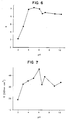
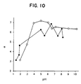
- Skin resistance (R) and skin irritation ( ⁇ ) as a function of pH are listed (i) in Table 10 for the cathodic reservoirs buffered with L-lysine or L-histidine; (ii) in Table 11 for the anodic reservoir buffered with citric acid, boric acid, or monobasic sodium phosphate, (iii) in Table 12 for the cathodic reservoirs buffered with L-histidine, L-lysine, or L-arginine, and (iv) in Table 13 for the cathodic reservoirs buffered with phosphoric acid and monobasic sodium phosphate.
- Irritation and resistance values from Table 10 are plotted versus pH in Figures 6 and 7, respectively.
- Irritation and resistance values from Table 11 are plotted versus pH in Figures 8 and 9, respectively.
- Irritation values from Tables 12 (open dot) and 13 (solid dot) are plotted versus pH in Figure 10.
- CATHODIC RESERVOIR COMPOSITION all include 0.1 M NaCl, 3% HPC, HCl q.s.
- buffer ions in this Example had a charge which was opposite the charge on the electrode (ie, positively charged buffer ions in the cathodic reservoir and negatively charged buffer ions in the anodic reservoir), a negligible amount of buffer ions were transported into the skin by electromi-gration.
- the skin irritation and skin resistance results were similar to those obtained in Example I, ie, cathodic reservoir pH's of less than about 4 and/or anodic reservoir pH's of greater than about 4 result in reduced skin resistance and reduced skin irritation compared to cathodic reservoir pH's greater than about 4 and/or anodic reservoir pH's less than about 4.
- buffering of the reservoirs alone is sufficient to reduce skin irritation and skin resistance, and the charge of the buffer ion (which charge effects whether or not the buffer ion is delivered at a significant rate into the skin) does not appear to significantly affect the results, at least during short periods (ie, up to 30 minutes) of electrotransport administration.
- Cathodic reservoir compositions containing sodium phosphate buffers (negatively charged buffer ions) were evaluated in this set of experi-ments. All compositions contained 0.05 M phosphoric acid, 0.1 M sodium chloride, 6% polyvinyl alcohol, 4% hydroxypropyl methylcellulose, and q.s. water. Sodium hydroxide was added q.s. to achieve the desired pH.
- the electrotransport was conducted on the inner arm of human volunteers.
- the skin contact area of the electrode reservoir gels ie, both the anodic gel and the cathodic gel
- the anodic electrode was silver foil and the cathodic electrode was silver chloride (ie, silver foil treated with HCl to form a surface layer of AgCl).
- the electrodes were connected to a DC power source which delivered a constant current of 0.51 mA, resulting in a current density of about 0.1 mA/cm 2 .
- Electrode gels were placed on the skin and connected to the DC power source.
- the power source delivered current through the gels for about 4 hours, after which time the electrodes were disconnected and the gels removed. After removal from the arms of the patients, the potassium content of the cathode gels was measured and potassium efflux ( ⁇ g/cm 2 ⁇ h) was calculated by dividing the measured potassium content by the product of gel skin contact area (ie, 5.1 cm 2 ) and time of application (ie, 4 h).
- Skin resistance was measured (as in Example I) at 1 hour after gel application and skin irritation measurements were taken about 24 hours after the gels were removed.
- Table 14 gives averaged results for six subjects.
- Figures 11 and 12 illustrate plots of the skin irritation and skin resistance values, respectively, as a function of cathodic reservoir pH.
- Table 14 also lists the average potassium efflux values at each pH.
- the potassium efflux was about 2 ⁇ g/cm 2 ⁇ h at pH values below about 4, when there was substantially no skin irritation or redness (ie, ⁇ of 0.2 or 0.6).
- the potassium efflux was greater than 10 ⁇ g/cm 2 ⁇ h at pH values of 6.7 and 8.9 when there was visible skin irritation and redness (ie, ⁇ of 2.6). While the mechanism responsible for the enhanced efflux of potassium accompanying skin irritation is unclear, the correlation between greater skin irritation/redness and higher potassium efflux is clearly demonstrated in Table 14.
- the applied electric current causes the skin cells to rupture or otherwise release their cytoplasmic potassium content.
- the cytoplasmic potassium concentration ie, the potassium concentration within the skin cells
- the cytoplasmic potassium concentration is about forty times greater than that of the interstitial fluid outside the skin cells. This at least suggests that skin irritation which occurred when electric current was applied at pH values greater than 4, caused expulsion of potassium from the interior of cells into the interstitial fluid, where it effluxed from the skin into the cathode hydrogel due to the applied electric field.
- Cathodic reservoir formulations containing histidine chloride buffer (ie, positively charged histidine buffer ions) and sodium citrate buffer (ie, negatively charged citrate buffer ions) at pH 3 and 4 were studied. All compositions contained 0.1 M buffer (histidine or citrate), 6% polyvinyl alcohol (PVA), 4% hydroxypropylmethylcellulose (HPMC), either HCl (for histidine) or NaOH (for citric acid) q.s. to the desired pH, and q.s. water.
- buffer histidine or citrate
- PVA polyvinyl alcohol
- HPMC 4% hydroxypropylmethylcellulose
- HCl for histidine
- NaOH for citric acid
- Example III the electrotransport was conducted on the inner arm of human volunteers.
- the electrode materials, the gel volume and skin contact area, the current, the current density and the wearing time were the same as in Example III.
- Table 15 presents skin irritation ( ⁇ ) as a function of hours after device removal for both citrate and histidine buffers at pH 3 and 4.
- Table 16 presents skin resistance (R) as a function of hours after device removal for both citrate and histidine buffers at pH 3 and 4.
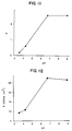
- Figures 13 and 14 show plots of skin irritation ( ⁇ ) and skin resistance (R), respectively, versus hours after device removal for citric acid and histidine buffers at pH 4.
- Figures 15 and 16 show plots of skin irritation ( ⁇ ) and skin resistance (R), respectively, versus hours after device removal for citric acid and histidine buffers at pH 3.
- HOURS AFTER DEVICE REMOVAL IRRITATION ( ⁇ ) AT pH 3 FOR HISTIDINE IRRITATION ( ⁇ ) AT pH 3 FOR CITRATE IRRITATION ( ⁇ ) AT pH 4 FOR HISTIDINE IRRITATION ( ⁇ ) AT pH 4 FOR CITRATE 1 0.4 0.7 0.6 0.9 4 0.3 1.4 0.7 1.5 24 -0.2 0.3 -0.4 0.7 HOURS AFTER DEVICE REMOVAL RESISTANCE AT pH 3 FOR HISTIDINE (KOHM ⁇ CM 2 ) RESISTANCE AT PH 3 FOR CITRATE (KOHM ⁇ CM 2 ) RESISTANCE AT PH 4 FOR HISTIDINE (KOHM ⁇ CM 2 ) RESISTANCE AT PH 4 FOR CITRATE (KOHM ⁇ CM 2 ) 0.5 5.3 3.7 10.1 6.1 1 2.6 2.0 5.6 3.4 2 1.7 1.3 4.3 3.7 3 1.6 1.4 4.0 2.4 4 2.0 1.2 3.1 2.0
- the cathodic reservoir contained positively charged histidine buffer, while in the other set, the cathodic reservoir contained negatively charged citrate buffer.
- the citrate buffer ions were transported into the skin by electromigration while the histidine buffer ions were not.
- skin resistance values for the two buffers were not significantly different (see Figs. 14 and 16)
- buffering the cathodic reservoir with histidine resulted in lower skin irritation compared to buffering with citric acid (see Figs. 13 and 15). Therefore, preventing or at least minimizing buffer transport into the skin (ie, through use of a cationic buffer in the cathodic reservoir and/or an anionic buffer in the anodic reservoir) is preferred for minimizing skin irritation.
- compositions were studied to determine the effect of cathodic reservoir pH on skin irritation. These compositions consisted of three ionic species (lactate, sulfate, and tartrate) in which two different pH's were evaluated for each ionic species. All reservoir electrolyte compositions were about 0.1 molar (M).
- Table 17 shows that, for each ionic species studied, a lower pH produced lower comparative irritation rankings. Further, for each ionic species, a lower pH produced a lower skin resistance.
- Cathodic reservoir formulations containing histidine chloride buffer adjusted to the desired pH with hydrochloric acid were placed on chest and arm sites of five different groups of human subjects. All sites were exposed to a DC current density of about 0.1 mA/cm 2 for 4 to 6 hours. After completion of each experiment, the potassium content of the cathode hydrogels was determined and potassium efflux values calculated.
- Table 18 summarizes the potassium efflux values calculated for the five groups of subjects. This data confirms the strong correlation between pH and potassium efflux discussed in Example III. As in Example III, cathodic pH values greater than 4 correlated with a four to five-fold enhancement in potassium efflux.
- An electrotransport device for delivering lidocaine HCl and having a configuration as illustrated in Figure 1, but without the membranes 30 and 32, is constructed.
- the anode 12 is comprised of silver and the cathode 14 is comprised of silver chloride.
- Both the anodic reservoir 16 and the cathodic reservoir 18 are comprised of a polyvinyl alcohol based hydrogel.
- Each of the reservoirs 16 and 18 has a volume of 1 cm 3 and a skin contact area of 10 cm 2 .
- the reservoir 16 gel is imbibed with an aqueous solution of lidocaine HCl and the reservoir 18 gel is imbibed with an aqueous saline solution.
- Londenerry NH, Model No. MI-402 is inserted into the cathodic reservoir 18 and connected to the power source in circuit layer 24.
- the potassium sensing probe, and the control circuit therefor, are set to measure the potassium concentration in the cathodic reservoir every 0.1 h.
- the sensed concentration is compared to the previously sensed concentration by an electronic comparator.
- the electrotransport was conducted on the inner arm of human volunteers.
- a custom electrotransport device was designed with an on-board power source, a current controlling electrical circuit and a waterproof backing material to permit patient bathing.
- the device had a foam housing which was adhered to the patients' skin throughout the experiment.
- the housing had cut-outs which held the anodic and cathodic reservoir gels.
- the skin contact area of the electrode reservoir gels ie, both the anodic gel and the cathodic gel
- were each approximately 2 cm 2 and the reservoir gel volume was about 250 ⁇ L.
- the anodic electrode was silver foil and the cathodic electrode was silver chloride (ie, silver foil treated with HCl to form a surface layer of AgCl).
- the electrodes were connected to the DC power source which delivered a constant current of 0.1 mA, resulting in an applied constant current density of about 50 ⁇ A/cm 2 .
- a fresh set of anode and cathode gels were worn for about 24 hours, after which time the electrodes were disconnected and the gels removed from the adhered (ie, to the skin) foam housing. Skin irritation and resistance measurements were taken and then a fresh set of anode and cathode gels were inserted into the housing. This schedule of wearing/measurement and gel replacement was repeated 3 times for a total wearing time of about 72 hours.
- Figures 17 and 18 illustrate plots of the skin irritation as a function of time for both the skin sites in contact with the anodic reservoir and the cathodic reservoir, respectively.
Abstract
Description
| Cationic Amino Acid Buffers for Cathodic Reservoir | ||
| AMINO ACID | pH RANGE FOR CATIONIC BEHAVIOR | PREFERRED pH RANGE FOR CATIONIC BEHAVIOR |
| histidine | 1-5 | 2-4 |
| lysine | 1-4 | 1.5-3.5 |
| arginine | 1-4 | 1.5-3.5 |
| aspartic acid | 1-3 | 2-3 |
| glutamic acid | 1-3.2 | 2-3.2 |
| cysteine | 1-4 | 2-3 |
| tyrosine | 1-4 | 2-3 |
| other amino acids | 1-4 | 2-3.5 |
| Anionic Acid Buffers for Cathodic Reservoir | ||
| BUFFER | pH RANGE FOR ANIONIC BEHAVIOR | PREFERRED pH RANGE FOR ANIONIC BEHAVIOR |
| aspartic acid | 3-5 | 3-4 |
| glutamic acid | 3.2-5 | 3.2-4 |
| citric acid | 1-5 | 2-4 |
| succinic acid | 2-5 | 3-4 |
| phosphoric acid | 1-5 | 2-4 |
| acetic acid | 3.5-5 | 3.5-4 |
| EDTA | 1-5 | 2-4 |
| lactic acid | 2.7-4.5 | 2.7-4 |
| benzoic acid | 3-5 | 3-4 |
| tartaric acid | 1.8-4.5 | 2.3-4 |
| maleic acid | 1-5 | 2-4 |
| fumaric acid | 1.8-5 | 2.3-4 |
| sulfuric acid | 1-3.2 | 1.5-3 |
| formic acid | 1.8-5 | 2.3-4 |
| malic acid | 2.1-5 | 2.6-4 |
| malonic acid | 1.7-5 | 2.1-4 |
| glutaric acid | 3-5 | 3-4 |
| adipic acid | 3-5 | 3-4 |
| Anionic Amino Acid Buffers for Anodic Reservoir | ||
| AMINO ACID | pH RANGE FOR ANIONIC BEHAVIOR | PREFERRED pH RANGE FOR ANIONIC BEHAVIOR |
| histidine | 7.5-10.5 | 7.5-10 |
| cysteine | 7-12 | 7.5-11.5 |
| tyrosine | 7.8-11.4 | 8.3-10.9 |
| lysine | 9.7-11.8 | 9.7-11.3 |
| arginine | 10.8-13 | 10.8-12 |
| aspartic acid | 3-5.2 | 4-4.6 |
| 8.5-11.1 | 9.1 -10.5 | |
| glutamic acid | 3.2-5.5 | 4-5 |
| 8.4-11 | 8.9-10.4 | |
| other amino acids | 8-12 | 9-11 |
| Zwitterion Buffers for Anodic Reservoir | |||
| ZWITTERION (Abbreviation) | ZWITTERION (Full Chemical Name) | pH RANGE FOR ANIONIC BEHAVIOR | PREFERRED pH RANGE FOR ANIONIC BEHAVIOR |
| MES | 2-(N-morpholino)-ethane sulfonic acid | 4.8-7.4 | 5.4-6.8 |
| PIPES | 1,4-piperazine-bis-(ethanesulfonic acid) | 5-7.6 | 5.6-7 |
| ADA | N-2-acetamido iminodiacetic acid | 5.3-7.9 | 5.9-7.3 |
| ACES | N-2(2-acetamido)-2-aminoethane sulfonic acid | 5.6-8.2 | 6.2-7.6 |
| BES | N,N-bis(2-hydroxyethyl)-2-aminoethane sulfonic acid | 5.9-8.4 | 6.4-7.8 |
| MOPS | 2-(N-morpholino)-propane sulfonic acid | 5.9-8.5 | 6.5-7.9 |
| TES | N-tris(hydroxymethyl) methyl-2-aminoethane sulfonic acid | 6.2-8.8 | 6.8-8.2 |
| HEPES | N-2-hydroxyethylpiperazine-N'-2-ethane sulfonic acid | 6.2-8.8 | 6.8-8.2 |
| EPPS | 4-(2-hydroxyethyl)-1-piperazine propane sulfonic acid | 6.7-9.3 | 7.3-8.7 |
| TAPS | N-tris(hydroxymethyl) methyl-2-aminopropane sulfonic acid | 7.1-9.7 | 7.7-9.1 |
| CHES | 2-cyclohexylamino-1-ethane sulfonic acid | 8.2-10.8 | 8.8-10.2 |
| CAPS | 3-cyclohexylamino-1-propanesulfonic acid | 9.1-11.7 | 9.7-11.1 |
| Anionic Acid Buffers for Anodic Reservoir | ||
| BUFFER | ANIONIC pH RANGE | PREFERRED ANIONIC pH RANGE |
| citric acid | 3-8 | 4-7 |
| succinic acid | 3-7.5 | 4-6.5 |
| phosphoric acid | 3-9 | 4-8 |
| maleic acid | 3-7.5 | 4-7 |
| malonic acid | 3-7.5 | 4-7 |
| acetic acid | 3-6 | 4-5.5 |
| boric acid | 8-10.5 | 8.5-9.9 |
| EDTA | 3-12 | 4-11 |
| lactic acid | 3-5 | 4-5 |
| benzoic acid | 3.5-5.5 | 4-5.5 |
| tartaric acid | 3-5.6 | 4-5.1 |
| fumaric acid | 3-6 | 4-5.1 |
| formic acid | 3.5-5 | 4-4.5 |
| malic acid | 3-6.3 | 4-5.8 |
| carbonic acid | 5.2-7.8 | 5.6-7.1 |
| glutamic acid | 3-7 | 4-6.5 |
| adipic acid | 3-7 | 4-6.5 |
| Cationic Bases and Amino Acids for the Anodic Reservoir | ||
| BASE BUFFER | pH RANGE FOR CATIONIC BEHAVIOR | PREFERRED pH RANGE FOR CATIONIC BEHAVIOR |
| tromethamine | 6.8-9.3 | 7.3-8.8 |
| triethanolamine | 6.5-9 | 7-8.5 |
| imidazole | 5.8-8.2 | 6.3-7.7 |
| ammonia | 8-10.5 | 8.5-10 |
| ethanolamine | 8.2-10.8 | 8.8-10.2 |
| diethanolamine | 7.6-10.2 | 8.2-9.6 |
| histidine | 3-7.5 | 4-7.5 |
| lysine | 7.7-9.7 | 8.2-9.7 |
| arginine | 7.8-10.8 | 8.3-10.8 |
| POLYMERIC BUFFER | ANIONIC pH RANGE | CATIONIC pH RANGE |
| polyacrylic acid | 3-8 | |
| polymethacrylic acid | 3-8 | |
| poly(styrene maleic anhydride) | 3-8 | |
| methacrylate/divinyl benzene copolymers | 3-8 | |
| poly(2-acrylamido-2-methylpropane sulfonate) | 1-5 | |
| copolymers of acrylic acid and long chain acrylate esters | 3-8 | |
| poly(methylvinyl ethermaleic acid) | 2-8 | |
| vinylpyrrolidone/quaternized dimethylaminoethylmethacrylate copolymers | 7-10 | |
| vinylcaprolactam/vinylpyrrolidone/dimethylamino ethylmethacrylate terpolymers | 7-10 | |
| polyvinylpyridine | 6-9 | |
| methacrylate/divinyl benzene copolymers | 6-9 |
| CATHODIC RESERVOIR pH | SKIN RESISTANCE (R) (KOhms·cm2) | SKIN IRRITATION (α) |
| 1.35 | 19.3 | 3.1 |
| 1.78 | 19.5 | 3.7 |
| 1.86 | 25.9 | 4.6 |
| 4.92 | 41.4 | 6.3 |
| 5.47 | 46.1 | 5.7 |
| 6.45 | 44.0 | 6.9 |
| 7.42 | 43.8 | 5.6 |
| 8.00 | 42.4 | 6.4 |
| 8.17 | 51.1 | 5.5 |
| BUFFER | ANODIC RESERVOIR pH | SKIN RESISTANCE (KOhms·cm2) | SKIN IRRITATION (α) |
| 0.15 M calcium chloride dihydrate | 4.88 | 48.3 | 5.1 |
| 0.15 M triethanolamine hydrochloride | 5.28 | 33.9 | 1.7 |
| 0.15 M magnesium chloride heptahydrate | 5.3 | 41.7 | 2.6 |
| 0.15 M diethanolamine hydrochloride | 5.5 | 29.8 | 1.7 |
| 0.15 M ammonium chloride | 5.58 | 26.4 | 2.0 |
| 0.15 M ethanolamine hydrochloride | 5.6 | 22.4 | 2.2 |
| 0.15 M potassium chloride | 5.65 | 22.7 | 1.6 |
| 0.15 M sodium chloride | 6.14 | 25.6 | 2.1 |
| CATHODIC RESERVOIR COMPOSITION (all include 0.1 M NaCl, 3% HPC, HCl q.s. to desired pH, and water q.s.) | CATHODIC RESERVOIR pH | SKIN RESISTANCE (R) (KOhms·cm2) | SKIN IRRITATION (α) |
| 0.05 M L-histidine base | 1.93 | 18.9 | 3.1 |
| 0.05 M L-histidine base | 2.92 | 32.4 | 4.7 |
| 0.05 M L-histidine base | 3.88 | 35.2 | 6.9 |
| 0.05 M L-histidine base | 4.93 | 37.6 | 7.2 |
| 0.05 M L-histidine base | 6.00 | 45.4 | 7.0 |
| 0.05 M L-lysine base | 6.55 | 32.1 | 6.4 |
| 0.05 M L-histidine base | 7.09 | 38.9 | 6.6 |
| 0.05 M L-lysine base | 8.98 | 30.1 | 6.4 |
| 0.05 M L-lysine base | 10.19 | 34.0 | 6.3 |
| ANODIC RESERVOIR COMPOSITION (all include 0.1 M NaCl, 3% HPC, NaOH q.s. to desired pH, and water q.s.) | ANODIC RESERVOIR pH | SKIN RESISTANCE (R) (KOhms·cm2) | SKIN IRRITATION (α) |
| 0.05 M citric acid | 2.11 | 51.6 | 4.7 |
| 0.05 M citric acid | 2.72 | 50.9 | 5.3 |
| 0.05 M citric acid | 3.62 | 45.6 | 4.0 |
| 0.05 M citric acid | 4.52 | 33.2 | 2.7 |
| 0.05 M citric acid | 5.31 | 29.6 | 2.7 |
| 0.05 M citric acid | 6.55 | 27.4 | 3.3 |
| 0.05 M sodium phosphate monobasic | 7.47 | 23.4 | 2.6 |
| 0.05 M boric acid | 8.80 | 22.5 | 2.5 |
| 0.05 M boric acid | 9.93 | 23.5 | 2.5 |
| CATHODIC RESERVOIR COMPOSITION (all include 0.1 M NaCl, 3% HPC, HCl q.s. to desired pH, and water q.s.) | CATHODIC RESERVOIR pH | SKIN IRRITATION (α) |
| 0.05 M L-histidine base | 1.93 | 3.1 |
| 0.05 M L-histidine base | 2.92 | 4.7 |
| 0.05 M L-histidine base | 3.88 | 6.9 |
| 0.05 M L-histidine base | 4.93 | 7.1 |
| 0.05 M L-histidine base | 6.00 | 7.0 |
| 0.05 M L-lysine base | 6.55 | 6.4 |
| 0.05 M L-histidine base | 7.09 | 6.6 |
| 0.05 M L-lysine base | 8.98 | 6.4 |
| 0.05 M L-arginine base | 10.19 | 6.4 |
| CATHODIC RESERVOIR COMPOSITION (all include 0.1 M NaCl, 3% HPC, NaOH q.s. to desired pH, and water q.s.) | CATHODIC RESERVOIR pH | SKIN IRRITATION (α) |
| 0.15 M phosphoric acid | 1.35 | 3.1 |
| 0.15 M phosphoric acid | 1.78 | 3.7 |
| 0.15 M phosphoric acid | 1.86 | 4.6 |
| 0.15 M monobasic sodium phosphate | 4.92 | 6.3 |
| 0.15 M monobasic sodium phosphate | 5.47 | 5.7 |
| 0.15 M monobasic sodium phosphate | 6.45 | 6.9 |
| 0.15 M monobasic sodium phosphate | 7.42 | 5.6 |
| 0.15 M monobasic sodium phosphate | 8.00 | 6.4 |
| 0.15 M monobasic sodium phosphate | 8.17 | 5.5 |
| CATHODIC RESERVOIR pH | SKIN RESISTANCE (R) (KOhm·cm2) | SKIN IRRITATION (α) | POTASSIUM EFFLUX (µg/cm2·h) |
| 3.5 | 9.1 | 0.2 | 2.1 |
| 4.2 | 10.6 | 0.6 | 2.0 |
| 6.7 | 26.9 | 2.6 | 13.4 |
| 8.9 | 26.0 | 2.6 | 18.6 |
| HOURS AFTER DEVICE REMOVAL | IRRITATION (α) AT | IRRITATION (α) AT | IRRITATION (α) AT | IRRITATION (α) AT |
| 1 | 0.4 | 0.7 | 0.6 | 0.9 |
| 4 | 0.3 | 1.4 | 0.7 | 1.5 |
| 24 | -0.2 | 0.3 | -0.4 | 0.7 |
| HOURS AFTER DEVICE REMOVAL | RESISTANCE AT | RESISTANCE AT | RESISTANCE AT | RESISTANCE AT |
| 0.5 | 5.3 | 3.7 | 10.1 | 6.1 |
| 1 | 2.6 | 2.0 | 5.6 | 3.4 |
| 2 | 1.7 | 1.3 | 4.3 | 3.7 |
| 3 | 1.6 | 1.4 | 4.0 | 2.4 |
| 4 | 2.0 | 1.2 | 3.1 | 2.0 |
| ELECTROLYTE | IONIC SPECIES | pH | AVERAGE IRRITATION RANKING AFTER 1 HOUR | AVERAGE IRRITATION RANKING AFTER 24 HOURS | RESISTANCE (KOhm·cm2) AFTER 5 HOURS |
| sodium lactate | lactate | 5.5 | 8.3 | 2.0 | 18.3 |
| lactic acid | lactate | 2.2 | 12.0 | 11.0 | 10.1 |
| sodium sulfate | sulfate | 6.0 | 12.6 | 12.0 | 15.5 |
| sodium hydrogen sulfate | sulfate | 1.5 | 24.0 | 24.6 | 12.4 |
| sodium tartrate | tartrate | 7.4 | 21.3 | 15.6 | 16.0 |
| sodium hydrogen tartrate | tartrate | 2.0 | 24.3 | 24.6 | 10.4 |
| CATHODE GEL pH | NUMBER OF SUBJECTS | NUMBER OF SITES TESTED | SITE LOCATION | POTASSIUM EFFLUX (µg/cm2·h) |
| 2.5 | 3 | 3 | Arm | 2.3 |
| 3 | 6 | 6 | Chest | 3.0 |
| 3 | 5 | 20 | Arm | 3.0 |
| 7 | 6 | 6 | Chest | 12.2 |
| 7 | 6 | 6 | Chest | 13.1 |
Claims (26)
- An electrotransport device (10) for delivering an agent through a body surface, comprising a cathodic reservoir (16 or 18) and an anodic reservoir (16 or 18), each of said reservoirs (16,18) being adapted to be placed in ion-transmitting relation with a body surface, one of said reservoirs (16,18) containing the agent to be delivered, and a source of electrical power (24) which can apply a voltage across the anodic and cathodic reservoirs (16,18) in order to deliver a predetermined level of electric current therethrough and through said body surface; characterised in that during electro-transport agent delivery,(a) said anodic reservoir is maintained at a pH above about 4; and/or(b) said cathodic reservoir is maintained at a pH below about 4.
- A device as claimed in claim 1, wherein the anodic reservoir pH is maintained within the range of above 4 to 10.
- A device as claimed in claim 1 or claim 2, wherein said anodic reservoir is buffered.
- A device as claimed in claim 3, wherein said anodic reservoir is buffered with an anionic buffer.
- A device as claimed in claim 4, wherein said anionic buffer is selected from the group consisting of histidine, lysine, arginine, aspartic acid, glutamic acid, cysteine, tyrosine and combinations thereof.
- A device as claimed in claim 3, wherein said anodic reservoir is buffered with:(a) a buffer selected from the group consisting of aspartic acid, glutamic acid, citric acid, succinic acid, phosphoric acid, acetic acid, EDTA, lactic acid, boric acid, carbonic acid, monobasic sodium phosphate, benzoic acid, tartaric acid, maleic acid, fumaric acid, sulfuric acid, formic acid, malic acid, malonic acid, glutaric acid and adipic acid;(b) a buffer selected from the group consisting of tromethamine, triethanolamine, imidazole, ammonia, ethanolamine, diethanolamine, histidine, lysine and arginine;(c) a buffer selected from the group consisting of calcium chloride dihydrate, triethanolamine hydrochloride, magnesium chloride heptahydrate, diethanolamine hydrochloride, ammonium chloride, ethanolamine hydrochloride, potassium chloride and sodium chloride;(d) a zwitterionic buffer selected from the group consisting of 2-(N-morpholino)-ethane sulfonic acid, 1,4-piperazine-bis-(ethanesulfonic acid), N-2-acetamido iminodiacetic acid, N-2(2-acetamido)-2-aminoethane sulfonic acid, N,N-bis(2-hydroxyethyl)-2-aminoethane sulfonic acid, 2-(N-morpholino)-propane sulfonic acid, N-tris hydroxymethyl) methyl-2-aminoethane sulfonic acid, N-2-hydroxyethyl piperazine-N'-2-ethane sulfonic acid, 4-(2-hydroxyethyl)-1-piperazine propane sulfonic acid, N-tris(hydroxymethyl) methyl-2-aminopropane sulfonic acid, 2-cyclohexylamino-1-ethane sulfonic acid, 3-cyclohexylamino-1-propanesulfonic acid and mixtures thereof; or(e) a polymeric buffer selected from the group consisting of polyacrylic acid, polymethacrylic acid, poly(styrene maleic anhydride), methacrylic/divinyl benzene copolymers, poly(2-acrylamido-2-methylpropane sulfonate), copolymers of acrylic acid and long chain acrylate esters and poly(methylvinyl ether-maleic acid).
- A device as claimed in any one of claims 1 to 6, wherein the cathodic reservoir pH is maintained in the range of 2 to below 4.
- A device as claimed in any one of claims 1 to 7, wherein the cathodic reservoir is buffered.
- A device as claimed in claim 8, wherein said cathodic reservoir is buffered with a cationic buffer.
- A device as claimed in claim 9, wherein said cationic buffer is selected from the group consisting of histidine, lysine, arginine, aspartic acid, glutamic acid, cysteine, tyrosine and combinations thereof.
- A device as claimed in claim 9, wherein said cathodic reservoir is buffered with:(a) a buffer selected from the group consisting of aspartic acid, glutamic acid, citric acid, succinic acid, phosphoric acid, acetic acid, EDTA, lactic acid, benzoic acid, tartaric acid, maleic acid, fumaric acid, sulfuric acid, formic acid, malic acid, malonic acid, glutaric acid and adipic acid; or(b) a polymeric buffer selected from the group consisting of vinylpyrrolidone/quaternized dimethylaminoethylmethacrylate copolymers, vinylcaprolactam/vinylpyrrolidone/dimethylamino ethylmethacrylate terpolymers, polyvinylpyrrolidone and methacrylate/divinyl benzene copolymers.
- A device as claimed in any one of claims 1 to 11, further comprising a secondary electrode in communication with:(a) the anodic reservoir, said secondary electrode comprising a material which can be reversibly oxidized and reduced, together with means for operating the secondary electrode to maintain the anodic reservoir pH above about 4; or(b) the cathodic reservoir, said secondary electrode comprising a material which can be reversibly oxidized and reduced, together with means for operating the secondary electrode to maintain the cathodic reservoir pH below about 4.
- A device as claimed in any one of claims 1 to 12, further comprising a potassium sensor for sensing the potassium content in the cathodic reservoir.
- A device as claimed in claim 13, comprising a means for altering the operation of the device when the potassium sensor senses a predetermined level of potassium efflux from the body surface into the cathodic reservoir.
- A device as claimed in any preceding claim, wherein:(a) the cathodic reservoir contains the agent to be delivered and the anodic reservoir is maintained at a pH above about 4; or(b) the anodic reservoir contains the agent to be delivered and the cathodic reservoir is maintained at a pH below about 4.
- A device as claimed in any preceding claim, wherein the anodic and cathodic reservoirs contain the agent to be delivered.
- An electrotransport delivery device (10) having an anodic electrode assembly (12, 16 or 14, 18), a cathodic electrode assembly (12, 16 or 14, 18), a source of electrical power (24) electrically connected to the electrode assemblies and an agent reservoir (16,18) in at least one of the electrode assemblies, characterised in that said device comprises a potassium sensor in said cathodic electrode assembly, and means for altering operating of the device when the potassium sensor senses a parameter selected from the group consisting of (i) a predetermined potassium content in the cathodic electrode assembly and (ii) a predetermined rate of change of potassium content in the cathodic electrode assembly.
- A device as claimed in claim 17, wherein said means for altering the operation of the delivery device comprises a means for reducing the level of electric current applied by the device.
- A device as claimed in claim 18, wherein the means for reducing the level of electric current applied by the device reduces the applied electric current to substantially zero.
- A device as claimed in claim 17, comprising means for emitting a signal when the potassium content in the cathodic electrode assembly reaches said predetermined value or when the rate of change of potassium content reaches said predetermined value.
- A device as claimed in any one of claims 17 to 20, wherein the potassium sensor comprises a potassium sensing electrode.
- An electrotransport delivery device (10) for delivery of an agent by electrotransport through a skin site, the device having an anodic electrode assembly (12, 16 or 14, 18), a cathodic electrode assembly (12, 16 or 14, 18), a source of electrical power (24) electrically connected to the electrode assemblies and an agent reservoir (16,18) in at least one of the electrode assemblies, characterised in that said device comprises:means for monitoring potassium efflux from the skin site during electrotransport agent delivery; andmeans for altering operation of the delivery device when the potassium efflux reaches a predetermined value.
- A device as claimed in claim 22, wherein said means for altering operation of the delivery device comprises a means for reducing the level of electric current applied by the device, means for emitting a signal or means for removing said delivery device from the skin site and reapplying the device to another skin site.
- A device as claimed in claim 23, wherein the means for reducing the level of the electric current applied by the device reduces the applied electric current to substantially zero.
- A device as claimed in any one of claims 22 to 24, comprising means for monitoring the potassium content in the cathodic electrode assembly.
- A device as claimed in claim 25, wherein the means for monitoring the potassium content is a sensor.
Applications Claiming Priority (3)
| Application Number | Priority Date | Filing Date | Title |
|---|---|---|---|
| US116660 | 1993-09-03 | ||
| US08/116,660 US5533971A (en) | 1993-09-03 | 1993-09-03 | Reduction of skin irritation during electrotransport |
| PCT/US1994/010054 WO1995006497A1 (en) | 1993-09-03 | 1994-08-31 | Reduction of skin irritation and resistance during electrotransport |
Publications (2)
| Publication Number | Publication Date |
|---|---|
| EP0717645A1 EP0717645A1 (en) | 1996-06-26 |
| EP0717645B1 true EP0717645B1 (en) | 1998-05-13 |
Family
ID=22368498
Family Applications (1)
| Application Number | Title | Priority Date | Filing Date |
|---|---|---|---|
| EP94929146A Expired - Lifetime EP0717645B1 (en) | 1993-09-03 | 1994-08-31 | Reduction of skin irritation and resistance during electrotransport |
Country Status (11)
| Country | Link |
|---|---|
| US (1) | US5533971A (en) |
| EP (1) | EP0717645B1 (en) |
| JP (1) | JP3664726B2 (en) |
| AT (1) | ATE165983T1 (en) |
| AU (1) | AU681447B2 (en) |
| CA (1) | CA2166490C (en) |
| DE (1) | DE69410279T2 (en) |
| DK (1) | DK0717645T3 (en) |
| ES (1) | ES2116618T3 (en) |
| NZ (1) | NZ274317A (en) |
| WO (1) | WO1995006497A1 (en) |
Families Citing this family (72)
| Publication number | Priority date | Publication date | Assignee | Title |
|---|---|---|---|---|
| US20050159699A1 (en) * | 1993-09-30 | 2005-07-21 | Vyteris, Inc. | Iontophoretic drug delivery device and reservoir and method of making same |
| US5752941A (en) * | 1994-02-15 | 1998-05-19 | Gruppo Lepetit S.P.A. | Central venous catheters loaded with antibiotics of the ramoplanin group preventing development of catheter related infections |
| US5990179A (en) * | 1995-04-28 | 1999-11-23 | Alza Corporation | Composition and method of enhancing electrotransport agent delivery |
| IE960312A1 (en) | 1995-06-02 | 1996-12-11 | Alza Corp | An electrotransport delivery device with voltage boosting¹circuit |
| AU6657396A (en) * | 1995-07-28 | 1997-02-26 | Novartis Ag | Transdermal system |
| WO1997047355A1 (en) * | 1996-06-12 | 1997-12-18 | Alza Corporation | Reduction of skin sensitization in electrotransport drug delivery |
| US6306384B1 (en) * | 1996-10-01 | 2001-10-23 | E-L Management Corp. | Skin battery cosmetic composition |
| US5800685A (en) * | 1996-10-28 | 1998-09-01 | Cardiotronics Systems, Inc. | Electrically conductive adhesive hydrogels |
| US6800278B1 (en) | 1996-10-28 | 2004-10-05 | Ballard Medical Products, Inc. | Inherently antimicrobial quaternary amine hydrogel wound dressings |
| FR2755842B1 (en) * | 1996-11-19 | 1999-04-23 | Lhd Lab Hygiene Dietetique | METHOD FOR MEASURING THE SKIN RESISTANCE OF A PATIENT SUBJECT TO A TRANSDERMAL ADMINISTRATION OF MEDICAMENT |
| WO1998035722A1 (en) * | 1997-02-17 | 1998-08-20 | Kowa Co., Ltd. | Device for iontophoresis |
| US6775569B2 (en) | 1997-11-05 | 2004-08-10 | Hisamitsu Pharmaceutical Co., Inc. | Electroporation device for in vivo delivery of therapeutic agents |
| DE69826705T2 (en) * | 1997-11-12 | 2006-02-23 | Alza Corp., Palo Alto | METHOD FOR THE DERIVATIVE ADMINISTRATION OF POLYPEPTIDES |
| US6374136B1 (en) * | 1997-12-22 | 2002-04-16 | Alza Corporation | Anhydrous drug reservoir for electrolytic transdermal delivery device |
| DE69919841T2 (en) * | 1998-01-28 | 2005-09-22 | Alza Corp., Palo Alto | ELECTROCHEMICAL REACTIVE CATHODE FOR ELECTRIC TRANSPORT DEVICE |
| ATE343411T1 (en) * | 1998-08-31 | 2006-11-15 | Travanti Pharma Inc | CONTROLLED MEDICATION DOSING DEVICE |
| US6532386B2 (en) | 1998-08-31 | 2003-03-11 | Johnson & Johnson Consumer Companies, Inc. | Electrotransort device comprising blades |
| US20050171021A1 (en) * | 1998-11-12 | 2005-08-04 | Cormier Michel J. | Buffered drug formulations for transdermal |
| US20060157355A1 (en) * | 2000-03-21 | 2006-07-20 | Semitool, Inc. | Electrolytic process using anion permeable barrier |
| US8852417B2 (en) | 1999-04-13 | 2014-10-07 | Applied Materials, Inc. | Electrolytic process using anion permeable barrier |
| US8236159B2 (en) | 1999-04-13 | 2012-08-07 | Applied Materials Inc. | Electrolytic process using cation permeable barrier |
| EP1177813A1 (en) * | 1999-04-13 | 2002-02-06 | Hisamitsu Pharmaceutical Co. Inc. | Iontophoresis device |
| EP1171195B1 (en) | 1999-04-16 | 2005-03-16 | Johnson & Johnson Consumer Companies, Inc. | Electrotransport delivery system comprising internal sensors |
| US20030040665A1 (en) * | 1999-05-28 | 2003-02-27 | E-Monitors, Inc. | Systems and methods of pH tissue monitoring |
| US6567679B1 (en) * | 1999-05-28 | 2003-05-20 | E-Monitors, Inc. | Method of using a pH tissue monitor |
| US6890553B1 (en) | 1999-07-08 | 2005-05-10 | Johnson & Johnson Consumer Companies, Inc. | Exothermic topical delivery device |
| AU6076200A (en) | 1999-07-08 | 2001-01-30 | Johnson & Johnson Consumer Companies, Inc. | Exothermic bandage |
| US7113821B1 (en) | 1999-08-25 | 2006-09-26 | Johnson & Johnson Consumer Companies, Inc. | Tissue electroperforation for enhanced drug delivery |
| US7133717B2 (en) * | 1999-08-25 | 2006-11-07 | Johnson & Johnson Consumer Companies, Inc. | Tissue electroperforation for enhanced drug delivery and diagnostic sampling |
| US6421561B1 (en) | 1999-12-30 | 2002-07-16 | Birch Point Medical, Inc. | Rate adjustable drug delivery system |
| US20060260946A1 (en) * | 2000-03-21 | 2006-11-23 | Semitool, Inc. | Copper electrolytic process using cation permeable barrier |
| US7404815B2 (en) * | 2000-05-01 | 2008-07-29 | Lifescan, Inc. | Tissue ablation by shear force for sampling biological fluids and delivering active agents |
| US6653014B2 (en) | 2001-05-30 | 2003-11-25 | Birch Point Medical, Inc. | Power sources for iontophoretic drug delivery systems |
| ITMI20012060A1 (en) * | 2001-10-05 | 2003-04-05 | Recordati Chem Pharm | NEW N-ACYLATED HETEROCYCLES |
| US7647099B2 (en) * | 2002-04-29 | 2010-01-12 | Rocky Mountain Biosystems, Inc. | Controlled release transdermal drug delivery |
| WO2004032963A2 (en) | 2002-10-04 | 2004-04-22 | Photokinetix Inc. | Photokinetic delivery of biologically active substances using pulsed incoherent light |
| US20050197618A1 (en) * | 2004-03-03 | 2005-09-08 | Iomed, Inc. | Improved buffer gel for iontophoresis electrodes |
| CA2580329C (en) | 2004-09-13 | 2015-01-06 | Chrono Therapeutics Inc. | Biosynchronous transdermal drug delivery |
| US8252321B2 (en) | 2004-09-13 | 2012-08-28 | Chrono Therapeutics, Inc. | Biosynchronous transdermal drug delivery for longevity, anti-aging, fatigue management, obesity, weight loss, weight management, delivery of nutraceuticals, and the treatment of hyperglycemia, alzheimer's disease, sleep disorders, parkinson's disease, aids, epilepsy, attention deficit disorder, nicotine addiction, cancer, headache and pain control, asthma, angina, hypertension, depression, cold, flu and the like |
| US20060173514A1 (en) * | 2005-02-02 | 2006-08-03 | Advanced Photodynamic Technologies, Inc. | Wound treatment device for photodynamic therapy and method of using same |
| US7856263B2 (en) * | 2005-04-22 | 2010-12-21 | Travanti Pharma Inc. | Transdermal systems for the delivery of therapeutic agents including granisetron using iontophoresis |
| WO2006127905A2 (en) | 2005-05-24 | 2006-11-30 | Chrono Therapeutics, Inc. | Portable drug delivery device |
| US20070048249A1 (en) | 2005-08-24 | 2007-03-01 | Purdue Research Foundation | Hydrophilized bactericidal polymers |
| BRPI0709965C1 (en) * | 2006-04-13 | 2011-12-20 | Nupathe Inc | pharmacokinetics of iontophoretic administration of sumatriptan |
| US7904146B2 (en) * | 2006-11-13 | 2011-03-08 | Travanti Pharma Inc. | Transdermal systems for the delivery of ionic agents directly to open wounds and surgically repaired incisions |
| US8197844B2 (en) | 2007-06-08 | 2012-06-12 | Activatek, Inc. | Active electrode for transdermal medicament administration |
| EP2162183B1 (en) * | 2007-06-25 | 2019-06-26 | AMW GmbH | Electrophoretic transdermal application system |
| EP2178598A4 (en) * | 2007-08-17 | 2012-08-15 | Isis Biopolymer Llc | Iontophoretic drug delivery system |
| US8275441B2 (en) * | 2007-11-02 | 2012-09-25 | Tyco Healthcare Group Lp | Electrodes possessing change indicator |
| CA2708497A1 (en) * | 2007-12-10 | 2009-06-18 | Isis Biopolymer Llc | Iontophoretic drug delivery device and software application |
| US8862223B2 (en) | 2008-01-18 | 2014-10-14 | Activatek, Inc. | Active transdermal medicament patch and circuit board for same |
| US8366600B2 (en) * | 2008-06-19 | 2013-02-05 | Nupathe Inc. | Polyamine enhanced formulations for triptan compound iontophoresis |
| US8155737B2 (en) * | 2008-06-19 | 2012-04-10 | Nupathe, Inc. | Pharmacokinetics of iontophoretic sumatriptan administration |
| ES2526118T3 (en) | 2008-12-30 | 2015-01-07 | Nupathe Inc. | Electronic control of drug delivery system |
| MX2011006925A (en) | 2008-12-31 | 2011-07-28 | Eyegate Pharma S A S | System and method for ocular iontophoresis with buffering. |
| US20110092881A1 (en) * | 2009-05-08 | 2011-04-21 | Isis Biopolymer Inc. | Iontophoretic device with contact sensor |
| TW201043287A (en) * | 2009-05-08 | 2010-12-16 | Isis Biopolymer Llc | Iontophoretic device with improved counterelectrode |
| EA201270227A1 (en) * | 2009-08-10 | 2012-10-30 | Нюпэф Инк. | METHODS OF IONOPHORETIC TREATMENT OF TIGHTNESS AND MIGRAINE |
| US20110087153A1 (en) * | 2009-10-13 | 2011-04-14 | Angelov Angel S | Transdermal Methods And Systems For The Delivery Of Rizatriptan |
| WO2012071175A1 (en) | 2010-11-23 | 2012-05-31 | Nupathe, Inc. | User-activated self-contained co-packaged iontophoretic drug delivery system |
| TWI558432B (en) | 2010-12-22 | 2016-11-21 | 帝國製藥股份有限公司 | Electorode pad for iontophoresis |
| WO2013006643A1 (en) | 2011-07-06 | 2013-01-10 | The Parkinson's Institute | Compositions and methods for treatment of symptoms in parkinson's disease patients |
| FI125075B (en) * | 2012-08-13 | 2015-05-29 | Novagent Oy | Active substance iontophoretic delivery system |
| US10105487B2 (en) | 2013-01-24 | 2018-10-23 | Chrono Therapeutics Inc. | Optimized bio-synchronous bioactive agent delivery system |
| FR3008320B1 (en) * | 2013-07-15 | 2018-04-20 | Centre Hospitalier Univ Grenoble | DEVICE FOR PREVENTING OR TREATING SKIN ULCERATION |
| CN103499519A (en) * | 2013-10-10 | 2014-01-08 | 河南科技大学 | Composite physical field transdermal drug delivery experiment device |
| US10213586B2 (en) | 2015-01-28 | 2019-02-26 | Chrono Therapeutics Inc. | Drug delivery methods and systems |
| AU2016228779A1 (en) | 2015-03-12 | 2017-09-07 | Chrono Therapeutics Inc. | Craving input and support system |
| US11285306B2 (en) | 2017-01-06 | 2022-03-29 | Morningside Venture Investments Limited | Transdermal drug delivery devices and methods |
| US20180340046A1 (en) | 2017-05-27 | 2018-11-29 | Poly Group LLC | Dispersible antimicrobial complex and coatings therefrom |
| US20180362678A1 (en) | 2017-06-16 | 2018-12-20 | Poly Group LLC | Polymeric antimicrobial surfactant |
| JP7420797B2 (en) | 2018-05-29 | 2024-01-23 | モーニングサイド ベンチャー インベストメンツ リミテッド | Drug delivery methods and systems |
Family Cites Families (41)
| Publication number | Priority date | Publication date | Assignee | Title |
|---|---|---|---|---|
| CA631424A (en) * | 1961-11-21 | H. Friedman Nathan | Electrically conductive systems | |
| US3989050A (en) * | 1972-09-19 | 1976-11-02 | Gilbert Buchalter | Process for utilizing certain gel compositions for electrical stimulation |
| US3991755A (en) * | 1973-07-27 | 1976-11-16 | Medicon, Inc. | Iontophoresis apparatus for applying local anesthetics |
| US4164226A (en) * | 1976-08-25 | 1979-08-14 | Robert Tapper | Iontophoretic burn-protection electrode structure |
| US4211222A (en) * | 1976-08-25 | 1980-07-08 | Robert Tapper | Iontophoretic burn-protection method |
| DE2727396C3 (en) * | 1977-06-18 | 1983-12-08 | Beiersdorf Ag, 2000 Hamburg | Electrically conductive, viscoelastic gel |
| US4163039A (en) * | 1978-01-11 | 1979-07-31 | Emrich Hinderk M | Diagnostic means for the rapid detection of mucoviscidosis |
| US4340047A (en) * | 1978-10-18 | 1982-07-20 | Robert Tapper | Iontophoretic treatment apparatus |
| US4301794A (en) * | 1978-10-18 | 1981-11-24 | Robert Tapper | Method for iontophoretic treatment |
| US4416274A (en) * | 1981-02-23 | 1983-11-22 | Motion Control, Inc. | Ion mobility limiting iontophoretic bioelectrode |
| JPS5810066A (en) * | 1981-07-10 | 1983-01-20 | 株式会社アドバンス | Plaster structure for ion tofuorese |
| US4846182A (en) * | 1982-01-11 | 1989-07-11 | Medtronic, Inc. | Method of preparing a fluid absorbent quantitative test device |
| US4444193A (en) * | 1982-01-11 | 1984-04-24 | Medtronic, Inc. | Fluid absorbent quantitative test device |
| US4708716A (en) * | 1983-08-18 | 1987-11-24 | Drug Delivery Systems Inc. | Transdermal drug applicator |
| CA1262564A (en) * | 1983-09-01 | 1989-10-31 | Minoru Sasaki | Iontophoresis device |
| US4747819A (en) * | 1984-10-29 | 1988-05-31 | Medtronic, Inc. | Iontophoretic drug delivery |
| US5135477A (en) * | 1984-10-29 | 1992-08-04 | Medtronic, Inc. | Iontophoretic drug delivery |
| US4744787A (en) * | 1984-10-29 | 1988-05-17 | Medtronic, Inc. | Iontophoresis apparatus and methods of producing same |
| US4702732A (en) * | 1984-12-24 | 1987-10-27 | Trustees Of Boston University | Electrodes, electrode assemblies, methods, and systems for tissue stimulation and transdermal delivery of pharmacologically active ligands |
| EP0461680A3 (en) * | 1985-06-10 | 1992-02-26 | Drug Delivery Systems Inc. | Programmable control and mounting system for transdermal drug applicator |
| US4722726A (en) * | 1986-02-12 | 1988-02-02 | Key Pharmaceuticals, Inc. | Method and apparatus for iontophoretic drug delivery |
| US4752285B1 (en) * | 1986-03-19 | 1995-08-22 | Univ Utah Res Found | Methods and apparatus for iontophoresis application of medicaments |
| US4915685A (en) * | 1986-03-19 | 1990-04-10 | Petelenz Tomasz J | Methods and apparatus for iontophoresis application of medicaments at a controlled ph through ion exchange |
| US4886489A (en) * | 1986-03-19 | 1989-12-12 | Jacobsen Stephen C | Flow-through methods and apparatus for iontophoresis application of medicaments at a controlled pH |
| US4717378A (en) * | 1986-03-31 | 1988-01-05 | Medtronic, Inc. | Methods for detecting dehydration of a biomedical hydrogel |
| US5042975A (en) * | 1986-07-25 | 1991-08-27 | Rutgers, The State University Of New Jersey | Iontotherapeutic device and process and iontotherapeutic unit dose |
| US4752372A (en) * | 1986-09-05 | 1988-06-21 | The United States Of America As Represented By The Administrator Of The National Aeronautics And Space Administration | Moving wall, continuous flow electronphoresis apparatus |
| US4786277A (en) * | 1986-11-21 | 1988-11-22 | Trustees Of Boston University | Electrodes, electrode assemblies, methods, and systems for tissue stimulation |
| KR900005223B1 (en) * | 1986-12-11 | 1990-07-21 | 가부시끼가이샤 호리바 세이사꾸쇼 | Method of measuring ion-concentration and the like and a calibrating sheet as well as a calibrating method of measuring device used therein |
| US4731049A (en) * | 1987-01-30 | 1988-03-15 | Ionics, Incorporated | Cell for electrically controlled transdermal drug delivery |
| AU609769B2 (en) * | 1987-02-10 | 1991-05-09 | Drug Delivery Systems Inc. | Electrolytic transdermal delivery of proteins |
| US4810418A (en) * | 1987-03-23 | 1989-03-07 | Minnesota Mining And Manufacturing Company | Electrically conductive composition |
| US4842701A (en) * | 1987-04-06 | 1989-06-27 | Battelle Memorial Institute | Combined electrophoretic-separation and electrospray method and system |
| US5362307A (en) * | 1989-01-24 | 1994-11-08 | The Regents Of The University Of California | Method for the iontophoretic non-invasive-determination of the in vivo concentration level of an inorganic or organic substance |
| US5203327A (en) * | 1988-09-08 | 1993-04-20 | Sudor Partners | Method and apparatus for determination of chemical species in body fluid |
| US4973303A (en) * | 1989-09-05 | 1990-11-27 | Empi, Inc. | pH buffered electrode for medical iontophoresis |
| US5088978A (en) * | 1990-01-26 | 1992-02-18 | Gensia Pharmaceuticals, Inc. | Apparatus and method for iontophoretic transfer |
| US5125894A (en) * | 1990-03-30 | 1992-06-30 | Alza Corporation | Method and apparatus for controlled environment electrotransport |
| US5116759A (en) * | 1990-06-27 | 1992-05-26 | Fiberchem Inc. | Reservoir chemical sensors |
| US5120545A (en) * | 1990-08-03 | 1992-06-09 | Alza Corporation | Reduction or prevention of sensitization to drugs |
| CA2122150A1 (en) * | 1991-08-26 | 1993-03-04 | Yie W. Chien | Iontotherapeutic device and process |
-
1993
- 1993-09-03 US US08/116,660 patent/US5533971A/en not_active Expired - Lifetime
-
1994
- 1994-08-31 DK DK94929146T patent/DK0717645T3/en active
- 1994-08-31 DE DE69410279T patent/DE69410279T2/en not_active Expired - Lifetime
- 1994-08-31 CA CA002166490A patent/CA2166490C/en not_active Expired - Fee Related
- 1994-08-31 WO PCT/US1994/010054 patent/WO1995006497A1/en active IP Right Grant
- 1994-08-31 AU AU78313/94A patent/AU681447B2/en not_active Ceased
- 1994-08-31 NZ NZ274317A patent/NZ274317A/en not_active IP Right Cessation
- 1994-08-31 EP EP94929146A patent/EP0717645B1/en not_active Expired - Lifetime
- 1994-08-31 JP JP50832395A patent/JP3664726B2/en not_active Expired - Fee Related
- 1994-08-31 AT AT94929146T patent/ATE165983T1/en not_active IP Right Cessation
- 1994-08-31 ES ES94929146T patent/ES2116618T3/en not_active Expired - Lifetime
Also Published As
| Publication number | Publication date |
|---|---|
| DK0717645T3 (en) | 1999-01-25 |
| EP0717645A1 (en) | 1996-06-26 |
| CA2166490C (en) | 2004-08-10 |
| DE69410279D1 (en) | 1998-06-18 |
| JP3664726B2 (en) | 2005-06-29 |
| AU7831394A (en) | 1995-03-22 |
| CA2166490A1 (en) | 1995-03-09 |
| ATE165983T1 (en) | 1998-05-15 |
| NZ274317A (en) | 1996-10-28 |
| DE69410279T2 (en) | 1999-01-07 |
| ES2116618T3 (en) | 1998-07-16 |
| US5533971A (en) | 1996-07-09 |
| WO1995006497A1 (en) | 1995-03-09 |
| JPH09504191A (en) | 1997-04-28 |
| AU681447B2 (en) | 1997-08-28 |
Similar Documents
| Publication | Publication Date | Title |
|---|---|---|
| EP0717645B1 (en) | Reduction of skin irritation and resistance during electrotransport | |
| US5624415A (en) | Reduction of skin irritation and resistance during electrotransport | |
| CA2181742C (en) | Reduction of skin irritation during electrotransport delivery | |
| AU2002303239B2 (en) | Transdermal electrotransport delivery device including an antimicrobial compatible reservoir composition | |
| CA2319638C (en) | Electrotransport electrode assembly having lower initial resistance | |
| EP0522011B1 (en) | Iontophoretic delivery device | |
| EP0804155B1 (en) | Composition and method for enhancing transdermal electrotransport agent delivery | |
| AU2002303239A1 (en) | Transdermal electrotransport delivery device including an antimicrobial compatible reservoir composition | |
| AU699648B2 (en) | Reduction of skin irritation and resistance during electrotransport | |
| CA2190370C (en) | Composition and method for enhancing transdermal electrotransport agent delivery |
Legal Events
| Date | Code | Title | Description |
|---|---|---|---|
| PUAI | Public reference made under article 153(3) epc to a published international application that has entered the european phase |
Free format text: ORIGINAL CODE: 0009012 |
|
| 17P | Request for examination filed |
Effective date: 19960403 |
|
| AK | Designated contracting states |
Kind code of ref document: A1 Designated state(s): AT BE CH DE DK ES FR GB GR IE IT LI LU MC NL PT SE |
|
| 17Q | First examination report despatched |
Effective date: 19960618 |
|
| GRAG | Despatch of communication of intention to grant |
Free format text: ORIGINAL CODE: EPIDOS AGRA |
|
| GRAG | Despatch of communication of intention to grant |
Free format text: ORIGINAL CODE: EPIDOS AGRA |
|
| GRAH | Despatch of communication of intention to grant a patent |
Free format text: ORIGINAL CODE: EPIDOS IGRA |
|
| GRAH | Despatch of communication of intention to grant a patent |
Free format text: ORIGINAL CODE: EPIDOS IGRA |
|
| GRAA | (expected) grant |
Free format text: ORIGINAL CODE: 0009210 |
|
| AK | Designated contracting states |
Kind code of ref document: B1 Designated state(s): AT BE CH DE DK ES FR GB GR IE IT LI LU MC NL PT SE |
|
| REF | Corresponds to: |
Ref document number: 165983 Country of ref document: AT Date of ref document: 19980515 Kind code of ref document: T |
|
| REG | Reference to a national code |
Ref country code: CH Ref legal event code: EP |
|
| REF | Corresponds to: |
Ref document number: 69410279 Country of ref document: DE Date of ref document: 19980618 |
|
| REG | Reference to a national code |
Ref country code: ES Ref legal event code: FG2A Ref document number: 2116618 Country of ref document: ES Kind code of ref document: T3 |
|
| ET | Fr: translation filed | ||
| PGFP | Annual fee paid to national office [announced via postgrant information from national office to epo] |
Ref country code: SE Payment date: 19980721 Year of fee payment: 5 |
|
| PGFP | Annual fee paid to national office [announced via postgrant information from national office to epo] |
Ref country code: PT Payment date: 19980731 Year of fee payment: 5 |
|
| ITF | It: translation for a ep patent filed |
Owner name: STUDIO TORTA S.R.L. |
|
| REG | Reference to a national code |
Ref country code: IE Ref legal event code: FG4D Free format text: 80358 |
|
| PGFP | Annual fee paid to national office [announced via postgrant information from national office to epo] |
Ref country code: GR Payment date: 19980819 Year of fee payment: 5 |
|
| REG | Reference to a national code |
Ref country code: CH Ref legal event code: NV Representative=s name: A. BRAUN, BRAUN, HERITIER, ESCHMANN AG PATENTANWAE |
|
| REG | Reference to a national code |
Ref country code: PT Ref legal event code: SC4A Free format text: AVAILABILITY OF NATIONAL TRANSLATION Effective date: 19980604 |
|
| REG | Reference to a national code |
Ref country code: DK Ref legal event code: T3 |
|
| PG25 | Lapsed in a contracting state [announced via postgrant information from national office to epo] |
Ref country code: MC Free format text: LAPSE BECAUSE OF NON-PAYMENT OF DUE FEES Effective date: 19990228 |
|
| PLBE | No opposition filed within time limit |
Free format text: ORIGINAL CODE: 0009261 |
|
| STAA | Information on the status of an ep patent application or granted ep patent |
Free format text: STATUS: NO OPPOSITION FILED WITHIN TIME LIMIT |
|
| 26N | No opposition filed | ||
| PG25 | Lapsed in a contracting state [announced via postgrant information from national office to epo] |
Ref country code: SE Free format text: THE PATENT HAS BEEN ANNULLED BY A DECISION OF A NATIONAL AUTHORITY Effective date: 19990830 |
|
| PG25 | Lapsed in a contracting state [announced via postgrant information from national office to epo] |
Ref country code: GR Free format text: LAPSE BECAUSE OF NON-PAYMENT OF DUE FEES Effective date: 19990831 |
|
| PG25 | Lapsed in a contracting state [announced via postgrant information from national office to epo] |
Ref country code: PT Free format text: LAPSE BECAUSE OF NON-PAYMENT OF DUE FEES Effective date: 20000229 |
|
| EUG | Se: european patent has lapsed |
Ref document number: 94929146.2 |
|
| REG | Reference to a national code |
Ref country code: PT Ref legal event code: MM4A Free format text: LAPSE DUE TO NON-PAYMENT OF FEES Effective date: 20000229 |
|
| REG | Reference to a national code |
Ref country code: GB Ref legal event code: IF02 |
|
| REG | Reference to a national code |
Ref country code: CH Ref legal event code: PFA Owner name: ALZA CORPORATION Free format text: ALZA CORPORATION#950 PAGE MILL ROAD P.O. BOX 10950#PALO ALTO CALIFORNIA 94303-0802 (US) -TRANSFER TO- ALZA CORPORATION#950 PAGE MILL ROAD P.O. BOX 10950#PALO ALTO CALIFORNIA 94303-0802 (US) |
|
| PGFP | Annual fee paid to national office [announced via postgrant information from national office to epo] |
Ref country code: IE Payment date: 20090818 Year of fee payment: 16 Ref country code: FR Payment date: 20090814 Year of fee payment: 16 Ref country code: ES Payment date: 20090902 Year of fee payment: 16 Ref country code: DK Payment date: 20090813 Year of fee payment: 16 |
|
| PGFP | Annual fee paid to national office [announced via postgrant information from national office to epo] |
Ref country code: NL Payment date: 20090803 Year of fee payment: 16 Ref country code: LU Payment date: 20090824 Year of fee payment: 16 Ref country code: GB Payment date: 20090826 Year of fee payment: 16 Ref country code: DE Payment date: 20090827 Year of fee payment: 16 Ref country code: CH Payment date: 20090814 Year of fee payment: 16 Ref country code: AT Payment date: 20090812 Year of fee payment: 16 |
|
| PGFP | Annual fee paid to national office [announced via postgrant information from national office to epo] |
Ref country code: BE Payment date: 20090825 Year of fee payment: 16 |
|
| PGFP | Annual fee paid to national office [announced via postgrant information from national office to epo] |
Ref country code: IT Payment date: 20090819 Year of fee payment: 16 |
|
| BERE | Be: lapsed |
Owner name: *ALZA CORP. Effective date: 20100831 |
|
| REG | Reference to a national code |
Ref country code: NL Ref legal event code: V1 Effective date: 20110301 |
|
| REG | Reference to a national code |
Ref country code: DK Ref legal event code: EBP |
|
| REG | Reference to a national code |
Ref country code: CH Ref legal event code: PL |
|
| GBPC | Gb: european patent ceased through non-payment of renewal fee |
Effective date: 20100831 |
|
| PG25 | Lapsed in a contracting state [announced via postgrant information from national office to epo] |
Ref country code: CH Free format text: LAPSE BECAUSE OF NON-PAYMENT OF DUE FEES Effective date: 20100831 Ref country code: LI Free format text: LAPSE BECAUSE OF NON-PAYMENT OF DUE FEES Effective date: 20100831 |
|
| REG | Reference to a national code |
Ref country code: FR Ref legal event code: ST Effective date: 20110502 |
|
| REG | Reference to a national code |
Ref country code: IE Ref legal event code: MM4A |
|
| PG25 | Lapsed in a contracting state [announced via postgrant information from national office to epo] |
Ref country code: IT Free format text: LAPSE BECAUSE OF NON-PAYMENT OF DUE FEES Effective date: 20100831 Ref country code: NL Free format text: LAPSE BECAUSE OF NON-PAYMENT OF DUE FEES Effective date: 20110301 Ref country code: AT Free format text: LAPSE BECAUSE OF NON-PAYMENT OF DUE FEES Effective date: 20100831 |
|
| REG | Reference to a national code |
Ref country code: DE Ref legal event code: R119 Ref document number: 69410279 Country of ref document: DE Effective date: 20110301 |
|
| PG25 | Lapsed in a contracting state [announced via postgrant information from national office to epo] |
Ref country code: DE Free format text: LAPSE BECAUSE OF NON-PAYMENT OF DUE FEES Effective date: 20110301 Ref country code: BE Free format text: LAPSE BECAUSE OF NON-PAYMENT OF DUE FEES Effective date: 20100831 Ref country code: FR Free format text: LAPSE BECAUSE OF NON-PAYMENT OF DUE FEES Effective date: 20100831 Ref country code: IE Free format text: LAPSE BECAUSE OF NON-PAYMENT OF DUE FEES Effective date: 20100831 |
|
| PG25 | Lapsed in a contracting state [announced via postgrant information from national office to epo] |
Ref country code: GB Free format text: LAPSE BECAUSE OF NON-PAYMENT OF DUE FEES Effective date: 20100831 Ref country code: DK Free format text: LAPSE BECAUSE OF NON-PAYMENT OF DUE FEES Effective date: 20100831 |
|
| REG | Reference to a national code |
Ref country code: ES Ref legal event code: FD2A Effective date: 20111019 |
|
| PG25 | Lapsed in a contracting state [announced via postgrant information from national office to epo] |
Ref country code: ES Free format text: LAPSE BECAUSE OF NON-PAYMENT OF DUE FEES Effective date: 20100901 |
|
| PG25 | Lapsed in a contracting state [announced via postgrant information from national office to epo] |
Ref country code: LU Free format text: LAPSE BECAUSE OF NON-PAYMENT OF DUE FEES Effective date: 20100831 |