EP0717115B1 - Process and installation for running a twin-vessel arc furnace - Google Patents
Process and installation for running a twin-vessel arc furnace Download PDFInfo
- Publication number
- EP0717115B1 EP0717115B1 EP95117126A EP95117126A EP0717115B1 EP 0717115 B1 EP0717115 B1 EP 0717115B1 EP 95117126 A EP95117126 A EP 95117126A EP 95117126 A EP95117126 A EP 95117126A EP 0717115 B1 EP0717115 B1 EP 0717115B1
- Authority
- EP
- European Patent Office
- Prior art keywords
- furnace
- vessel
- blowing
- slagging
- electrodes
- Prior art date
- Legal status (The legal status is an assumption and is not a legal conclusion. Google has not performed a legal analysis and makes no representation as to the accuracy of the status listed.)
- Expired - Lifetime
Links
- 238000000034 method Methods 0.000 title claims abstract description 27
- 238000009434 installation Methods 0.000 title 1
- XEEYBQQBJWHFJM-UHFFFAOYSA-N Iron Chemical compound [Fe] XEEYBQQBJWHFJM-UHFFFAOYSA-N 0.000 claims abstract description 28
- 238000007664 blowing Methods 0.000 claims abstract description 28
- QVGXLLKOCUKJST-UHFFFAOYSA-N atomic oxygen Chemical compound [O] QVGXLLKOCUKJST-UHFFFAOYSA-N 0.000 claims abstract description 22
- 239000001301 oxygen Substances 0.000 claims abstract description 22
- 229910052760 oxygen Inorganic materials 0.000 claims abstract description 22
- 238000002844 melting Methods 0.000 claims abstract description 17
- 230000008018 melting Effects 0.000 claims abstract description 17
- 229910000805 Pig iron Inorganic materials 0.000 claims abstract description 14
- 229910052742 iron Inorganic materials 0.000 claims abstract description 14
- 239000000155 melt Substances 0.000 claims abstract description 13
- 239000000463 material Substances 0.000 claims abstract description 12
- 229910000831 Steel Inorganic materials 0.000 claims abstract description 11
- 239000010959 steel Substances 0.000 claims abstract description 11
- 235000008733 Citrus aurantifolia Nutrition 0.000 claims abstract description 10
- 235000011941 Tilia x europaea Nutrition 0.000 claims abstract description 10
- 239000004571 lime Substances 0.000 claims abstract description 10
- 238000010079 rubber tapping Methods 0.000 claims abstract description 8
- 244000007645 Citrus mitis Species 0.000 claims abstract 2
- 229910000514 dolomite Inorganic materials 0.000 claims abstract 2
- 239000010459 dolomite Substances 0.000 claims abstract 2
- 239000002893 slag Substances 0.000 claims description 15
- 239000007788 liquid Substances 0.000 claims description 13
- 238000004519 manufacturing process Methods 0.000 claims description 6
- 239000003245 coal Substances 0.000 claims description 4
- 238000012545 processing Methods 0.000 claims description 4
- 239000000446 fuel Substances 0.000 claims description 3
- 238000001816 cooling Methods 0.000 claims description 2
- 239000011819 refractory material Substances 0.000 claims description 2
- FGUUSXIOTUKUDN-IBGZPJMESA-N C1(=CC=CC=C1)N1C2=C(NC([C@H](C1)NC=1OC(=NN=1)C1=CC=CC=C1)=O)C=CC=C2 Chemical compound C1(=CC=CC=C1)N1C2=C(NC([C@H](C1)NC=1OC(=NN=1)C1=CC=CC=C1)=O)C=CC=C2 FGUUSXIOTUKUDN-IBGZPJMESA-N 0.000 claims 1
- 238000003723 Smelting Methods 0.000 claims 1
- 239000000654 additive Substances 0.000 claims 1
- 238000005266 casting Methods 0.000 claims 1
- 239000002826 coolant Substances 0.000 abstract description 2
- 239000002184 metal Substances 0.000 abstract 1
- 229910052751 metal Inorganic materials 0.000 abstract 1
- 238000009628 steelmaking Methods 0.000 abstract 1
- 239000007789 gas Substances 0.000 description 9
- 238000010891 electric arc Methods 0.000 description 4
- 239000003546 flue gas Substances 0.000 description 4
- UGFAIRIUMAVXCW-UHFFFAOYSA-N Carbon monoxide Chemical compound [O+]#[C-] UGFAIRIUMAVXCW-UHFFFAOYSA-N 0.000 description 3
- 238000009529 body temperature measurement Methods 0.000 description 3
- 238000010309 melting process Methods 0.000 description 3
- 238000013021 overheating Methods 0.000 description 3
- 238000005070 sampling Methods 0.000 description 2
- 239000007787 solid Substances 0.000 description 2
- 229910001341 Crude steel Inorganic materials 0.000 description 1
- 239000011449 brick Substances 0.000 description 1
- 238000006243 chemical reaction Methods 0.000 description 1
- 238000004140 cleaning Methods 0.000 description 1
- 238000013461 design Methods 0.000 description 1
- 238000006477 desulfuration reaction Methods 0.000 description 1
- 230000023556 desulfurization Effects 0.000 description 1
- 238000012423 maintenance Methods 0.000 description 1
- 238000006213 oxygenation reaction Methods 0.000 description 1
- 230000035515 penetration Effects 0.000 description 1
- 239000002994 raw material Substances 0.000 description 1
Images


Classifications
-
- C—CHEMISTRY; METALLURGY
- C21—METALLURGY OF IRON
- C21C—PROCESSING OF PIG-IRON, e.g. REFINING, MANUFACTURE OF WROUGHT-IRON OR STEEL; TREATMENT IN MOLTEN STATE OF FERROUS ALLOYS
- C21C5/00—Manufacture of carbon-steel, e.g. plain mild steel, medium carbon steel or cast steel or stainless steel
- C21C5/52—Manufacture of steel in electric furnaces
- C21C5/5252—Manufacture of steel in electric furnaces in an electrically heated multi-chamber furnace, a combination of electric furnaces or an electric furnace arranged for associated working with a non electric furnace
-
- C—CHEMISTRY; METALLURGY
- C21—METALLURGY OF IRON
- C21C—PROCESSING OF PIG-IRON, e.g. REFINING, MANUFACTURE OF WROUGHT-IRON OR STEEL; TREATMENT IN MOLTEN STATE OF FERROUS ALLOYS
- C21C5/00—Manufacture of carbon-steel, e.g. plain mild steel, medium carbon steel or cast steel or stainless steel
- C21C5/52—Manufacture of steel in electric furnaces
-
- C—CHEMISTRY; METALLURGY
- C21—METALLURGY OF IRON
- C21C—PROCESSING OF PIG-IRON, e.g. REFINING, MANUFACTURE OF WROUGHT-IRON OR STEEL; TREATMENT IN MOLTEN STATE OF FERROUS ALLOYS
- C21C5/00—Manufacture of carbon-steel, e.g. plain mild steel, medium carbon steel or cast steel or stainless steel
- C21C5/28—Manufacture of steel in the converter
- C21C5/30—Regulating or controlling the blowing
- C21C5/35—Blowing from above and through the bath
-
- F—MECHANICAL ENGINEERING; LIGHTING; HEATING; WEAPONS; BLASTING
- F27—FURNACES; KILNS; OVENS; RETORTS
- F27B—FURNACES, KILNS, OVENS, OR RETORTS IN GENERAL; OPEN SINTERING OR LIKE APPARATUS
- F27B13/00—Furnaces with both stationary charge and progression of heating, e.g. of ring type, of type in which segmental kiln moves over stationary charge
-
- F—MECHANICAL ENGINEERING; LIGHTING; HEATING; WEAPONS; BLASTING
- F27—FURNACES; KILNS; OVENS; RETORTS
- F27B—FURNACES, KILNS, OVENS, OR RETORTS IN GENERAL; OPEN SINTERING OR LIKE APPARATUS
- F27B3/00—Hearth-type furnaces, e.g. of reverberatory type; Tank furnaces
- F27B3/04—Hearth-type furnaces, e.g. of reverberatory type; Tank furnaces of multiple-hearth type; of multiple-chamber type; Combinations of hearth-type furnaces
-
- Y—GENERAL TAGGING OF NEW TECHNOLOGICAL DEVELOPMENTS; GENERAL TAGGING OF CROSS-SECTIONAL TECHNOLOGIES SPANNING OVER SEVERAL SECTIONS OF THE IPC; TECHNICAL SUBJECTS COVERED BY FORMER USPC CROSS-REFERENCE ART COLLECTIONS [XRACs] AND DIGESTS
- Y02—TECHNOLOGIES OR APPLICATIONS FOR MITIGATION OR ADAPTATION AGAINST CLIMATE CHANGE
- Y02P—CLIMATE CHANGE MITIGATION TECHNOLOGIES IN THE PRODUCTION OR PROCESSING OF GOODS
- Y02P10/00—Technologies related to metal processing
- Y02P10/20—Recycling
Definitions
- the invention relates to a method and a device to operate a double-vessel arc furnace, for steel production, the furnace vessels I and II can be closed by means of an oven lid a pivotable furnace cover arranged electrodes, with blowing lances for oxygen, fine lime, coal, gaseous or liquid fuels, whereby for Carrying out the procedure of one of the two Furnace vessels, I or II, completely off the power supply is separated, but the second vessel on the power supply remains; that the oven vessel removed from the power supply loaded with molten pig iron, scrap and other metallic feedstocks and then closed with an oven lid and refreshed with oxygen and that the furnace vessel on the power supply more metallurgical work, such as melting and overheating by means of electrodes until the melt taps.
- Electric arc furnaces are mainly used as single units used and operated.
- Furnace systems have been developed in recent years been because of the worsening scarcity of Energy and input resources are inexpensive and environmentally friendly steel production had.
- EP 0 483 322 includes a melting unit two melting vessels arranged side by side known that with a heater for the feed of melt energy and two arranged side by side Melting furnaces each one through a vessel lid sealable oven vessel is equipped, each Melting furnace two gas through openings as well as lockable Has gas lines, each having a gas passage opening of one furnace with one Gas passage opening of the other melting furnace connect so that for preheating metallic insert the furnace gases generated during the melting process one furnace in the other Melting furnace can be initiated, with each Melting furnace on one side of an outer segment of the Vessel lid through one, in a support structure fortified shaft is replaced in its upper Area a lockable loading opening for the Feed material and a gas passage opening of the relevant Has melting furnace.
- a connecting line provided between the two furnaces is the flue gas from the electrical Operating furnace by the separate from the power supply Oven sucked off, while during suction of the flue gas from the oven, which is disconnected from the mains the flue gas connection of the other furnace for gas cleaning is interrupted.
- the two known double furnace systems are also for the processing of molten pig iron, in particular for high areas of application that cover up to half of the metallic insert can go, in none Appropriate and not designed for this.
- the object of the invention is therefore a To create methods and an apparatus in which a double furnace system energy-saving, environmentally friendly, inexpensive and the available raw materials / energies correspondingly steel is produced, whereby liquid Pig iron in the order of 50% and more of the solid feed material, for example sponge iron, Ore, scrap and. a. metallic feedstocks used becomes.
- the double-vessel arc furnace which can be closed with a swiveling furnace lid, with a high current supply from the transformer to the electrodes arranged in a swivel device equipped.
- Both pivoting furnace covers have one in the middle round opening through which the electrodes into the Oven vessel are retracted. These round openings are moved by a movable one if necessary Carrier device attached additional cover closed, which itself has a central opening, through which a blowing lance is lowered into the furnace vessel can be.
- top lances are guided through the middle of the furnace lid and are on the side of a structure via a swivel arm attached.
- the top lance will preferably designed as a three-hole lance.
- Oxygen, fine lime, coal, gaseous and liquid fuels also from the side arranged lances are fed to the furnace vessel.
- the oven vessel or vessels are below the cooled one Brick wall lined with additional ff material, at the same time the volume of the stove is reduced by a downward depression, in the area below the oxygen blowing lance, enlarged.
- the furnace vessels can both on a toothed tilting cradle with the appropriate trajectory as well as after DE 42 44 228 on non-toothed, sliding tilting cradles, which each run on at least two roles, be relocated so that the furnace during deslagging can be tilted down to -10 ° without the on the Swivel device arranged not tilting Electrodes and the blowing lance that does not tip over be damaged because of the known arc furnaces with toothed tilting cradle the cover lifting and Swiveling device on the tilting furnace platform is arranged.
- the furnace lid can be used instead of a swivel mechanism a lid undercarriage on which the oxygen blowing lance (Top lance) can be attached in one Fixed lifting and lowering device and laterally be removed from the furnace.
- This solution requires however, an additional fully equipped one Electrode cover on the swivel device is attached and in each case on furnace vessel I or II can be lowered.
- the laterally movable Oven covers only have an opening in the middle to carry out the top lance.
- the additional cover with the movable or swiveling carrying device can be omitted with this solution.
- the double furnace vessel system can also be used as a DC arc furnace operated, the Furnace vessels with only one lid electrode (Cathode) and with a bottom electrode (anode) in the Furnace stove to be equipped.
- furnace vessel I While in furnace vessel I first after the converter / BOF phase is working - freshening the liquid Pig iron with oxygen, coolants and lime - runs in furnace vessel II the arc furnace / EAF phase, d. H. Melting of sponge iron / scrap, limescale and possibly Coal addition with reduced oxygen supply, from.
- Furnace vessel I converter / BOF phase
- Furnace vessel II Arc furnace / EAF phase
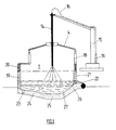
- the arc furnace (1) shown in Fig. 1 draws compared to a conventional arc furnace a recess (25) in the furnace vessel (1) in the hearth (24) as well as by an increased lining (20) of the furnace vessel (1) above the parting line.
- This measure means the bricked-up furnace volume enlarged for the converter or BOF phase, that when blowing oxygen and fine lime over the the lance (14, 15, 16) of the reaction chamber can be raised and lowered sufficient for the slag (26) and the melt (27) is large.
- the furnace cover (4) can be replaced by a not shown Lid, lifting and swiveling device or alternatively raised by a movable cover undercarriage and swiveled out of the area of the furnace vessel (1) or be moved.
- Fig. 2 shows a plan view of the double vessel system with the two vessels (1, 2) on one Swivel device (8, 9) attached electrodes (3), the pivoting furnace covers (4, 6), (5, 7), the blowing lance (14, 15, 16) and the exhaust pipe (11, 12) to the exhaust pipes to a dedusting system.
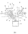
- Fig. 3 shows a plan view of a double vessel system in the operating state.
- Furnace vessel I (1) works in the arc furnace / EAF phase with in the furnace cover (4) on the swivel device (8, 9) pivoted electrodes (3)
- Furnace vessel II (2) works in the converter / BOF phase and with the swiveling furnace cover (5, 7) the top lance (14, 16) and an additional cover (13) covered.
- the tap hole (23) of the two melting vessels (1, 2) is parallel to the power supply (9) and Transformer (10) arranged.
- Fig. 4 shows a plan view of a double vessel system (1, 2) with a cover carriage (28, 29) on which the Oven cover (4, 6) and the blowing lance (14, 15, 16) Rails (31) are arranged to be movable.
- the cover carriage (28) with the furnace cover (4) from Oven vessel (1) has been moved sideways, the oven vessel (1) is open so that the swivel device (8) with Swivel the electrode cover (30) onto the furnace vessel (1) can.
- Fig. 5 shows a plan view of a double vessel system (1, 2) with a movable on rails (31) Cover undercarriage (28, 29) in the operating state.
- the electrode cover (30) lies on the furnace vessel (1) on, the cover carriage (28) with the top lance (14) has moved to the side, the furnace vessel (1) is working in the arc furnace / BOF phase.
- Oven lid (5) rests on oven vessel (2), over which Top lance (14, 15, 16) is blown oxygen to the filled pig iron to fresh, oven vessel (2) works in the converter / BOF phase.
Abstract
Description
Die Erfindung betrifft ein Verfahren und eine Vorrichtung zum Betreiben eines Doppelgefäß-Lichtbogenofens, zur Stahlerzeugung, wobei die Ofengefäße I und II durch Ofendeckel verschließbar sind, mit auf einem schwenkbaren Ofendeckel angeordneten Elektroden, mit Einblaslanzen für Sauerstoff, Feinkalk, Kohle, gasförmigen oder flüssigen Brennstoffen, wobei zur Durchführung des Verfahrens eines der beiden Ofengefäße, I oder II, vollständig vom Stromnetz getrennt wird, das zweite Gefäß jedoch am Stromnetz verbleibt; daß das vom Stromnetz genommene Ofengefäß mit flüssigem Roheisen, Schrott und anderen metallischen Einsatzstoffen beschickt und anschließend mit einem Ofendeckel verschlossen und mit Sauerstoff gefrischt wird und daß das am Stromnetz befindliche Ofengefäß weitere metallurgische Arbeiten, wie Einschmelzen und Überhitzen mittels Elektroden bis zum Abstich der Schmelze, durchführt.The invention relates to a method and a device to operate a double-vessel arc furnace, for steel production, the furnace vessels I and II can be closed by means of an oven lid a pivotable furnace cover arranged electrodes, with blowing lances for oxygen, fine lime, coal, gaseous or liquid fuels, whereby for Carrying out the procedure of one of the two Furnace vessels, I or II, completely off the power supply is separated, but the second vessel on the power supply remains; that the oven vessel removed from the power supply loaded with molten pig iron, scrap and other metallic feedstocks and then closed with an oven lid and refreshed with oxygen and that the furnace vessel on the power supply more metallurgical work, such as melting and overheating by means of electrodes until the melt taps.
Für die Rohstahlerzeugung sind eine Reihe von Verfahrenswegen bekannt, die über den klassischen Weg Hochofen - Konverter überwiegend heißes, flüssiges Roheisen in Kombination mit Schrott, Erz, Eisenschwamm u. a. metallischen Einsatzstoffen verwenden und Schmelzgefäße, beispielsweise Elektro-Lichtbogenöfen, bei denen überwiegend kalte bzw. vorgewärmte Einsatzstoffe, wie Schrott und Eisenschwamm, zum Einsatz kommen.There are a number of process routes for the production of crude steel known that the classic way blast furnace - Converter mainly hot, liquid pig iron in combination with scrap, ore, sponge iron, etc. a. use metallic feedstocks and melting vessels, for example electric arc furnaces where predominantly cold or preheated feedstocks, such as Scrap and sponge iron are used.
Elektro-Lichtbogenöfen werden überwiegend als Einzelaggregate verwendet und betrieben.Electric arc furnaces are mainly used as single units used and operated.
In den letzten Jahren sind Ofenanlagen entwickelt worden, die wegen der sich verschärfenden Knappheit von Ressourcen an Energie und Einsatzstoffen eine kostengünstige und umweltfreundliche Stahlerzeugung zum Ziel hatten. Furnace systems have been developed in recent years been because of the worsening scarcity of Energy and input resources are inexpensive and environmentally friendly steel production had.
Hierzu zählen die bekannten Maßnahmen, beim Betrieb von Elektro-Lichtbogenöfen, aus dem Elektroofen abgesaugte, heiße Rauchgase zur Vorwärmung des Chargiergutes, in der Regel Schrott, zu verwenden.These include the known measures when operating Electric arc furnaces, extracted from the electric furnace, hot flue gases to preheat the cargo, in usually scrap to use.
Aus der EP 0 483 322 ist ein Einschmelzaggregat mit zwei nebeneinander angeordneten Schmelzgefäßen bekannt, das mit einer Heizeinrichtung für die Zufuhr von Schmelzenergie und zwei nebeneinander angeordneten Schmelzöfen aus jeweils einem durch einen Gefäßdeckel verschließbaren Ofengefäß ausgerüstet ist, wobei jeder Schmelzofen zwei Gasdurchtrittsöffnungen sowie absperrbare Gasleitungen aufweist, welche jeweils eine Gasdurchtrittsöffnung des einen Schmelzofens mit einer Gasdurchtrittsöffnung des anderen Schmelzofens verbinden, so daß zum Vorheizen von metallischem Einsatzmaterial die beim Schmelzprozeß entstehenden Ofengase des einen Schmelzofens in den jeweils anderen Schmelzofen eingeleitet werden können, wobei bei jedem Schmelzofen an einer Seite ein äußeres Segment des Gefäßdeckels durch einen, in einer Haltekonstruktion befestigten Schacht ersetzt ist, der in seinem oberen Bereich eine verschließbare Beschickungsöffnung für das Einsatzmaterial und eine Gasdurchtrittsöffnung des betreffenden Schmelzofens aufweist.EP 0 483 322 includes a melting unit two melting vessels arranged side by side known that with a heater for the feed of melt energy and two arranged side by side Melting furnaces each one through a vessel lid sealable oven vessel is equipped, each Melting furnace two gas through openings as well as lockable Has gas lines, each having a gas passage opening of one furnace with one Gas passage opening of the other melting furnace connect so that for preheating metallic insert the furnace gases generated during the melting process one furnace in the other Melting furnace can be initiated, with each Melting furnace on one side of an outer segment of the Vessel lid through one, in a support structure fortified shaft is replaced in its upper Area a lockable loading opening for the Feed material and a gas passage opening of the relevant Has melting furnace.
Aus der DE 43 02 285 A1 ist ein Verfahren und Einrichtung zum Betreiben einer Zweiofenanlage bekannt.DE 43 02 285 A1 describes a method and device known for operating a two-furnace system.
In dieser Stahlwerksanlage mit Doppelofeneinrichtung soll Stahl erschmolzen werden, wobei das Verfahren durch folgende Schritte gekennzeichnet ist:In this steel plant with double furnace equipment steel is to be melted using the process is characterized by the following steps:
Es wird einer der beiden Öfen zum Einschmelzen des
darin befindlichen Schrottes mit elektrischem Strom
versorgt und der andere wird vollständig vom Netz
getrennt;
Über eine zwischen beiden Öfen vorgesehene Verbindungsleitung wird das Rauchgas aus dem im elektrischen Betrieb befindlichen Ofen durch den vom Stromnetz getrennten Ofen abgesaugt, wobei während des Absaugens des Rauchgases aus dem vom Stromnetz getrennten Ofen die Rauchgasverbindung des anderen Ofens zur Gasreinigung unterbrochen wird.Via a connecting line provided between the two furnaces is the flue gas from the electrical Operating furnace by the separate from the power supply Oven sucked off, while during suction of the flue gas from the oven, which is disconnected from the mains the flue gas connection of the other furnace for gas cleaning is interrupted.
Der Einsatz von festem Roheisen im Lichtbogenofen ist wegen der langen Aufschmelzzeit der Masseln mengenmäßig beschränkt, die Verarbeitung (Frischen) von flüssigem Roheisen ist im Elektro-Lichtbogenofen bisher nicht zufriedenstellend gelöst worden.The use of solid pig iron in the arc furnace is because of the long melting time of the ingots limited, the processing (freshness) of liquid Pig iron is not yet in the electric arc furnace has been satisfactorily resolved.
Auch die beiden bekannten Doppelofenanlagen sind für die Verarbeitung von flüssigem Roheisen, insbesondere für hohe Einsatzbereiche, die bis über die Hälfte des metallischen Einsatzes hinausgehen können, in keiner Weise geeignet und auch dafür nicht konzipiert. The two known double furnace systems are also for the processing of molten pig iron, in particular for high areas of application that cover up to half of the metallic insert can go, in none Appropriate and not designed for this.
Die Aufgabe der Erfindung besteht deshalb darin, ein Verfahren und eine Vorrichtung zu schaffen, bei der in einer Doppelofenanlage energiesparend, umweltschonend, kostengünstig und den verfügbaren Rohstoffen/Energien entsprechend Stahl erzeugt wird, wobei flüssiges Roheisen in einer Größenordnung von 50 % und mehr des festen Einsatzmaterials, beispielsweise Eisenschwamm, Erz, Schrott u. a. metallische Einsatzstoffe, verwendet wird.The object of the invention is therefore a To create methods and an apparatus in which a double furnace system energy-saving, environmentally friendly, inexpensive and the available raw materials / energies correspondingly steel is produced, whereby liquid Pig iron in the order of 50% and more of the solid feed material, for example sponge iron, Ore, scrap and. a. metallic feedstocks used becomes.
Die Lösung der Aufgabe erfolgt durch die
kennzeichnenden Merkmale der Ansprüche 1 und 2, die
Unteransprüche betreffen eine weitere vorteilhafte
Ausgestaltung der Vorrichtung.The task is solved by
characteristic features of
Erfindungsgemäß wird der Doppelgefäß-Lichtbogenofen, der durch schwenkbare Ofendeckel verschließbar ist, mit einer Hochstromzuführung vom Transformator zu dem auf einer Schwenkvorrichtung angeordneten Elektroden ausgerüstet.According to the invention, the double-vessel arc furnace, which can be closed with a swiveling furnace lid, with a high current supply from the transformer to the electrodes arranged in a swivel device equipped.
Beide schwenkbaren Ofendeckel weisen in der Mitte eine runde Öffnung auf, durch die die Elektroden in das Ofengefäß eingefahren werden. Diese runden Öffnungen werden bei Bedarf durch einen an einer verfahrbaren Tragvorrichtung befestigten Zusatzdeckel verschlossen, der selbst eine mittig angeordnete Öffnung aufweist, durch die eine Blaslanze in das Ofengefäß abgesenkt werden kann.Both pivoting furnace covers have one in the middle round opening through which the electrodes into the Oven vessel are retracted. These round openings are moved by a movable one if necessary Carrier device attached additional cover closed, which itself has a central opening, through which a blowing lance is lowered into the furnace vessel can be.
Die Sauerstoffblaslanzen, hier sogenannte Top-Lanzen, werden mittig durch den Ofendeckel geführt und sind seitlich an einem Tragwerk über einen Schwenkarm befestigt. The oxygen blowing lances, here so-called top lances, are guided through the middle of the furnace lid and are on the side of a structure via a swivel arm attached.
Sauerstoff und Kühlmedien werden der Top-Lanze über separate Schläuche zugeführt. Die Top-Lanze wird bevorzugt als Dreiloch-Lanze ausgeführt.Oxygen and cooling media become the top lance supplied separate hoses. The top lance will preferably designed as a three-hole lance.
In bekannter Weise können Sauerstoff, Feinkalk, Kohle, gasförmige und flüssige Brennstoffe auch durch seitlich angeordnete Lanzen dem Ofengefäß zugeführt werden.Oxygen, fine lime, coal, gaseous and liquid fuels also from the side arranged lances are fed to the furnace vessel.
Das bzw. die Ofengefäße werden unterhalb der gekühlten Ofenwand mit zusätzlichem ff-Material ausgemauert, gleichzeitig wird das Volumen des Ofenherdes durch eine nach unten angeordnete Vertiefung, im Bereich unterhalb der Sauerstoffblaslanze, vergrößert.The oven vessel or vessels are below the cooled one Brick wall lined with additional ff material, at the same time the volume of the stove is reduced by a downward depression, in the area below the oxygen blowing lance, enlarged.
Durch Hinzufügen einer zusätzlichen Ausmauerung im unteren Bereich des Ofengefäßes und durch die Vertiefung im Ofenherd wird ein höherer Badspiegel erreicht, der eine entsprechende Eindringtiefe des Sauerstoffstrahles analog zum LD-Verfahren erlaubt und gleichzeitig einen Schutz der Ausmauerung des Ofenherdes während des Frischens mit Sauerstoff gewährleistet.By adding an additional lining in the lower area of the furnace vessel and through the Deepening in the oven stove becomes a higher bath level reached a corresponding depth of penetration of the Oxygen jet analogous to the LD process allowed and at the same time protecting the lining of the Oven cooker during oxygenation guaranteed.
Die Ofengefäße können sowohl auf einer verzahnten Kippwiege mit entsprechender Ablaufbahn als auch nach der DE 42 44 228 auf nichtverzahnten, gleitenden Kippwiegen, die jeweils auf mindestens zwei Rollen ablaufen, verlagert sein, damit der Ofen während des Abschlackens bis zu -10° gekippt werden kann, ohne daß die auf der Schwenkvorrichtung angeordneten nicht mitkippenden Elektroden und die nicht mitkippende Blaslanze beschädigt werden, da bei den bekannten Lichtbogenöfen mit verzahnter Kippwiege die Deckel-Hub- und Schwenkvorrichtung auf der mitkippenden Ofenbühne angeordnet ist. The furnace vessels can both on a toothed tilting cradle with the appropriate trajectory as well as after DE 42 44 228 on non-toothed, sliding tilting cradles, which each run on at least two roles, be relocated so that the furnace during deslagging can be tilted down to -10 ° without the on the Swivel device arranged not tilting Electrodes and the blowing lance that does not tip over be damaged because of the known arc furnaces with toothed tilting cradle the cover lifting and Swiveling device on the tilting furnace platform is arranged.
Die Ofendeckel können anstelle eines Schwenkwerkes an einem Deckelfahrwerk, auf denen auch die Sauerstoffblaslanze (Top-Lanze) angebracht sein kann, in einer Hub- und Senkvorrichtung befestigt und jeweils seitlich vom Ofengefäß entfernt werden. Diese Lösung erfordert jedoch einen zusätzlichen komplett ausgerüsteten Elektrodendeckel, der auf der Schwenkvorrichtung befestigt ist und jeweils auf Ofengefäß I oder II abgesenkt werden kann. Die seitlich verfahrbaren Ofendeckel weisen lediglich in der Mitte eine Öffnung zur Durchführung der Top-Lanze auf. Die Zusatzdeckel mit der verfahrbaren bzw. schwenkbaren Tragvorrichtung können bei dieser Lösung entfallen.The furnace lid can be used instead of a swivel mechanism a lid undercarriage on which the oxygen blowing lance (Top lance) can be attached in one Fixed lifting and lowering device and laterally be removed from the furnace. This solution requires however, an additional fully equipped one Electrode cover on the swivel device is attached and in each case on furnace vessel I or II can be lowered. The laterally movable Oven covers only have an opening in the middle to carry out the top lance. The additional cover with the movable or swiveling carrying device can be omitted with this solution.
Schließlich kann die Doppelofen-Gefäßanlage auch als Gleichstrom-Lichtbogenofen betrieben werden, wobei die Ofengefäße jeweils mit nur einer Deckelelektrode (Kathode) und mit einer Bodenelektrode (Anode) im Ofenherd ausgerüstet werden.Finally, the double furnace vessel system can also be used as a DC arc furnace operated, the Furnace vessels with only one lid electrode (Cathode) and with a bottom electrode (anode) in the Furnace stove to be equipped.
Das erfindungsgemäße Verfahren zur Herstellung von Stahl im Lichtbogenofen durch Einsatz von flüssigem Roheisen im Verbund mit Eisenschwamm und/oder Schrott, bei gleichzeitiger Zugabe von Sauerstoff und Kalk, wird in einer sogenannten Konverter/BOF- und Lichtbogenofen-/EAF-Phase durchgeführt.The inventive method for the production of Steel in the arc furnace through the use of liquid Pig iron combined with sponge iron and / or scrap, with the simultaneous addition of oxygen and lime in a so-called converter / BOF and arc furnace / EAF phase carried out.
Während in Ofengefäß I zunächst nach der Konverter-/BOF-Phase gearbeitet wird - Frischen des flüssigen Roheisens mit Sauerstoff, Kühlmitteln und Kalk -, läuft in Ofengefäß II die Lichtbogenofen-/EAF-Phase, d. h. Einschmelzen von Eisenschwamm/Schrott, Kalk- und evtl. Kohlezugabe bei verminderter Sauerstoffzufuhr, ab.While in furnace vessel I first after the converter / BOF phase is working - freshening the liquid Pig iron with oxygen, coolants and lime - runs in furnace vessel II the arc furnace / EAF phase, d. H. Melting of sponge iron / scrap, limescale and possibly Coal addition with reduced oxygen supply, from.
Nach Beendigung der jeweiligen Verfahrensschritte in einem der beiden Ofengefäße werden in den beiden Ofengefäßen jeweils die nächsten Phasen der Stahlherstellung durchgeführt.After completion of the respective process steps in one of the two furnace vessels are in the two furnace vessels the next phases of steel production carried out.
In den beiden jeweils zeitlich parallel ablaufenden Phasen werden in den beiden Gefäßen im einzelnen folgende Verfahrensschritte durchgeführt:In the two, each running in parallel Phases are in the two vessels in detail carried out the following process steps:
In Ofengefäß II wird jetzt die Konverter/BOF-Phase, in Ofengefäß I wird jetzt die Lichtbogenofen-/EAF-Phase durchgeführt.The converter / BOF phase is now in furnace vessel II Furnace vessel I now becomes the arc furnace / EAF phase carried out.
Ein Ausführungsbeispiel der erfindungsgemäßen Vorrichtung wird anhand von schematischen Zeichnungen näher erläutert. An embodiment of the invention Device is based on schematic drawings explained in more detail.
Es zeigen:
- Fig. 1
- eine Seitenansicht des Ofengefäßes,
- Fig. 2
- eine Draufsicht auf die Doppelgefäßanlage,
- Fig. 3
- eine Draufsicht auf die Doppelgefäßanlage im Betriebszustand,
- Fig. 4
- eine Draufsicht auf die Doppelgefäßanlage mit einem Deckel-Fahrwerk,
- Fig. 5
- eine Draufsicht auf die Doppelgefäßanlage im Betriebszustand mit einem Deckel-Fahrwerk.
- Fig. 1
- a side view of the furnace vessel,
- Fig. 2
- a plan view of the double vessel system,
- Fig. 3
- a plan view of the double vessel system in the operating state,
- Fig. 4
- a plan view of the double vessel system with a cover chassis,
- Fig. 5
- a plan view of the double vessel system in the operating state with a cover undercarriage.
Der in Fig. 1 dargestellte Lichtbogenofen (1) zeichnet sich gegenüber einem herkömmlichen Lichtbogenofen durch eine Vertiefung (25) des Ofengefäßes (1) im Herd (24) sowie durch eine erhöhte Ausmauerung (20) des Ofengefäßes (1) oberhalb der Trennfuge aus.The arc furnace (1) shown in Fig. 1 draws compared to a conventional arc furnace a recess (25) in the furnace vessel (1) in the hearth (24) as well as by an increased lining (20) of the furnace vessel (1) above the parting line.
Durch diese Maßnahme wird das ausgemauerte Ofenvolumen für die Konverter- bzw. BOF-Phase soweit vergrößert, daß beim Einblasen von Sauerstoff und Feinkalk über die heb- und senkbare Blaslanze (14, 15, 16) der Reaktionsraum für die Schlacke (26) und der Schmelze (27) ausreichend groß dimensioniert ist.This measure means the bricked-up furnace volume enlarged for the converter or BOF phase, that when blowing oxygen and fine lime over the the lance (14, 15, 16) of the reaction chamber can be raised and lowered sufficient for the slag (26) and the melt (27) is large.
Das Ofengefäß wird in bekannter Weise im oberen Teil mit wassergekühlten Wandelementen (18) und einem wassergekühlten Ofendeckel (4) ausgerüstet, im unteren Teil, in Höhe der wassergekühlten Schlackentür (21) und des Vorwärmers (22) werden die Gefäßwände (19, 20) sowie Abstich (23), Herd (24) und Vertiefung (25) mit feuerfestem Material zugestellt. The furnace vessel is in a known manner in the upper part with water-cooled wall elements (18) and a water-cooled furnace lid (4) in the lower Part, at the level of the water-cooled slag door (21) and of the preheater (22), the vessel walls (19, 20) and racking (23), stove (24) and recess (25) with delivered refractory material.
Der Ofendeckel (4) kann durch eine nicht dargestellte Deckel-, Hub- und Schwenkvorrichtung bzw. alternativ durch ein verfahrbares Deckel-Fahrwerk angehoben und aus dem Bereich des Ofengefäßes (1) geschwenkt bzw. verfahren werden.The furnace cover (4) can be replaced by a not shown Lid, lifting and swiveling device or alternatively raised by a movable cover undercarriage and swiveled out of the area of the furnace vessel (1) or be moved.
Fig. 2 zeigt eine Draufsicht auf die Doppel-Gefäßanlage mit den beiden Gefäßen (1, 2), den auf einer Schwenkvorrichtung (8, 9) angebrachten Elektroden (3), den schwenkbar angeordneten Ofendeckeln (4, 6), (5, 7), der Blaslanze (14, 15, 16) und den Abgasstutzen (11, 12) zu den Abgasleitungen zu einer Entstaubungsanlage.Fig. 2 shows a plan view of the double vessel system with the two vessels (1, 2) on one Swivel device (8, 9) attached electrodes (3), the pivoting furnace covers (4, 6), (5, 7), the blowing lance (14, 15, 16) and the exhaust pipe (11, 12) to the exhaust pipes to a dedusting system.
An einer Deckeltragvorrichtung (17) ist ein Zusatzdeckel (13) angeordnet, der eine Öffnung im Ofendeckel (4, 5) verschließt, wenn mit der Blaslanze (14) anstelle der auf der Schwenkvorrichtung (8, 9) angeordneten Elektroden (3) gearbeitet wird.There is an additional cover on a cover support device (17) (13) arranged an opening in the furnace lid (4, 5) closes when with the blowing lance (14) instead arranged on the swivel device (8, 9) Electrodes (3) is worked.
Fig. 3 zeigt eine Draufsicht auf eine Doppelgefäßanlage im Betriebszustand.Fig. 3 shows a plan view of a double vessel system in the operating state.
Ofengefäß I (1) arbeitet in der Lichtbogenofen-/ EAF-Phase mit in den Ofendeckel (4) auf der Schwenkvorrichtung (8, 9) eingeschwenkten Elektroden (3), Ofengefäß II (2) arbeitet in der Konverter-/BOF-Phase und ist durch den schwenkbaren Ofendeckel (5, 7) mit der Top-Lanze (14, 16) sowie durch einen Zusatzdeckel (13) abgedeckt.Furnace vessel I (1) works in the arc furnace / EAF phase with in the furnace cover (4) on the swivel device (8, 9) pivoted electrodes (3), Furnace vessel II (2) works in the converter / BOF phase and with the swiveling furnace cover (5, 7) the top lance (14, 16) and an additional cover (13) covered.
Das Abstichloch (23) der beiden Schmelzgefäße (1, 2) ist parallel in Richtung Stromzuführung (9) und Transformator (10) angeordnet.The tap hole (23) of the two melting vessels (1, 2) is parallel to the power supply (9) and Transformer (10) arranged.
Fig. 4 zeigt eine Draufsicht auf eine Doppelgefäßanlage (1, 2) mit einem Deckelfahrwerk (28, 29), an denen die Ofendeckel (4, 6) und die Blaslanze (14, 15, 16) auf Schienen (31) verfahrbar angeordnet sind.Fig. 4 shows a plan view of a double vessel system (1, 2) with a cover carriage (28, 29) on which the Oven cover (4, 6) and the blowing lance (14, 15, 16) Rails (31) are arranged to be movable.
Das Deckelfahrwerk (28) mit dem Ofendeckel (4) von Ofengefäß (1) ist seitlich abgefahren, das Ofengefäß (1) ist offen, so daß die Schwenkvorrichtung (8) mit dem Elektrodendeckel (30) auf das Ofengefäß (1) einschwenken kann.The cover carriage (28) with the furnace cover (4) from Oven vessel (1) has been moved sideways, the oven vessel (1) is open so that the swivel device (8) with Swivel the electrode cover (30) onto the furnace vessel (1) can.
Fig. 5 zeigt eine Draufsicht auf eine Doppelgefäßanlage (1, 2) mit einem auf Schienen (31) verfahrbaren Deckelfahrwerk (28, 29) im Betriebszustand.Fig. 5 shows a plan view of a double vessel system (1, 2) with a movable on rails (31) Cover undercarriage (28, 29) in the operating state.
Der Elektrodendeckel (30) liegt auf dem Ofengefäß (1) auf, das Deckel-Fahrwerk (28) mit der Top-Lanze (14) ist seitlich abgefahren, das Ofengefäß (1) arbeitet in der Lichtbogenofen-/BOF-Phase.The electrode cover (30) lies on the furnace vessel (1) on, the cover carriage (28) with the top lance (14) has moved to the side, the furnace vessel (1) is working in the arc furnace / BOF phase.
Ofendeckel (5) liegt auf Ofengefäß (2) auf, über die Top-Lanze (14, 15, 16) wird Sauerstoff geblasen, um das eingefüllte Roheisen zu frischen, Ofengefäß (2) arbeitet in der Konverter-/BOF-Phase. Oven lid (5) rests on oven vessel (2), over which Top lance (14, 15, 16) is blown oxygen to the filled pig iron to fresh, oven vessel (2) works in the converter / BOF phase.
- 11
- Ofengefäß IOven vessel I
- 22nd
- Ofengefäß IIOven vessel II
- 33rd
- ElektrodenElectrodes
- 44th
- Ofendeckel IOven cover I
- 55
- Ofendeckel IIOven cover II
- 66
- Deckel-Schwenkwerk ICover swivel mechanism I
- 77
- Deckel-Schwenkwerk IILid swivel mechanism II
- 88th
- Schwenkvorrichtung für 3Swiveling device for 3
- 99
- StromzuführungPower supply
- 1010th
- Transformatortransformer
- 1111
- Abgasstutzen Ofen IExhaust pipe furnace I
- 1212th
- Abgasstutzen Ofen IIExhaust pipe furnace II
- 1313
- ZusatzdeckelAdditional lid
- 1414
- Blaslanze/ToplanzeBlow lance / top lance
- 1515
- Lanzen-Hub- und SenkvorrichtungLance lifting and lowering device
- 1616
- MedienzuführungMedia feed
- 1717th
- Deckel-TragvorrichtungLid carrying device
- 1818th
- Gekühlte OfenwandChilled furnace wall
- 1919th
- AusmauerungLining
- 2020th
- Zusatz-AusmauerungAdditional brickwork
- 2121
- SchlackentürSlag door
- 2222
- VorwärmerPreheater
- 2323
- AbstichlochTap hole
- 2424th
- OfenherdStove
- 2525th
- Vertiefung im OfenherdDeepening in the stove
- 2626
- OfenschlackeFurnace slag
- 2727
- Schmelzemelt
- 2828
- Deckel-Fahrwerk ILid chassis I
- 2929
- Deckel-Fahrwerk IILid undercarriage II
- 3030th
- Ofendeckel mit ElektrodenOven cover with electrodes
- 3131
- Schienenrails
Claims (7)
- Process for running a twin-vessel arc furnace for steel production, whereby one of the two furnace vessels, I or II, is completely disconnected from the electric circuit but the second furnace vessel remains connected to the electric circuit; the furnace vessel disconnected from the electric circuit is loaded with liquid pig iron, scrap iron and other metallic charge materials, then closed with a furnace cover and oxidated, while the furnace vessel connected to the electric circuit performs further metallurgic operations such as smelting down and superheating by means of electrodes until the tapping of the melt,
characterized by the following processing steps for furnace vessel I or II:For furnace vessel I:a) deoxidizing of the residual slag and of the pool, charging of liquid pig iron up to a proportion of 70 % of the metallic charge in furnace vessel I (1),b) blowing of oxygen via a blowing lance (14) from above through the furnace cover (4) with simultaneous addition of cooling materials, e.g. ore, scrap iron, sponge iron or other metallic charge materials according to the thermal balance of the blowing process, as well as addition of slag-forming additives, e.g. lime, dolomite etc., according to the analysis of the metallic charge materials,c) continuous slagging off and/or partial slagging off during interruption of the blowing or at the end of the blowing respectively of the furnace slag (26) through the slag door (21) and via the economizer (22) during process step b),d) retraction and slewing away of the blowing lance (14, 16) of furnace vessel I (1),e) slewing in of the electrodes (3) located on a slewing device (8) and connected with a high-current line (9) from the transformer (10) onto furnace vessel I (1),f) charging the electrodes (3) of furnace vessel I (1) with current with simultaneous addition of the remaining metallic charge materials (ore, scrap iron, sponge iron or others) until attainment of the tapping weight as well as lime addition and further blowing in of oxygen through lateral lances during the melting down and superheating process,g) continuous partial slagging off and/or partial slagging off during the process or during the process end respectively of the furnace slag (26) through the slag door (21) and via the economizer (22) during process step f) with concluding superheating of the melt (27).h) tapping of the melt (27) into a steel casting ladle through the tapping hole (23), whereby one part of the melt (27) remains as a pool in the hearth (24, 25) of furnace vessel I (1).For furnace vessel II :execution of process steps e through h in furnace vessel II (2) parallel to the sequence of process steps a through d in furnace vessel I (1),execution of process steps a through d in furnace vessel II (2) parallel to the sequence of process steps e through h in furnace vessel I (1). - Twin-vessel arc furnace, whereby furnace vessels I and II are closable with furnace covers, with electrodes located on a slewing device, with blow-in lances for oxygen, coal, lime, gaseous or liquid fuels, for execution of the process according to claim 1,
characterized in thatone single slewing device (8, 9) with electrodes (3) is located for each furnace vessel (1, 2) and that a lance lifting and lowering device (15) for a blowing lance (14, 16) is located for each furnace cover (4, 5),that the hearth (24) of the furnace vessel (1, 2) has a depression (25),and that the side walls (19) of the furnace vessel (1, 2) blocked with refractory material are equipped with all-round additional walling (20) located over them. - Twin-vessel arc furnace according to claim 2,
characterized in thatan ancillary cover (13) attached to a moveable supporting device (17) is placeable centrically onto the furnace covers (4, 5). - Twin-vessel arc furnace according to claim 2,
characterized in thatthe furnace covers (4 and 5) are removable from furnace vessel I and II by means of cover traversing gear (28, 29). - Twin-vessel arc furnace according to claim 2,
characterized in thatthe liftable and lowerable, water-cooled blowing lance (14, 16) is configured as a multi-hole lance. - Twin-vessel arc furnace according to claim 2,
characterized in thatadditional blowing lances are inserted by known means through the cooled furnace wall (18), through the brick-lined furnace walls (19, 20) and/or through the slag door (21) into the furnace vessel I, II (1,2). - Twin-vessel arc furnace according to claim 2,
characterized in thatthe furnace vessels I and II (1, 2) with the furnace covers (4, 5) are equipped with only one electrode (3) on the slewing device (8) and with a hearth electrode in the furnace hearth (24, 25) as a direct current arc furnace.
Applications Claiming Priority (2)
| Application Number | Priority Date | Filing Date | Title |
|---|---|---|---|
| DE19944445209 DE4445209C2 (en) | 1994-12-17 | 1994-12-17 | Method and device for operating a double-vessel arc furnace |
| DE4445209 | 1994-12-17 |
Publications (2)
| Publication Number | Publication Date |
|---|---|
| EP0717115A1 EP0717115A1 (en) | 1996-06-19 |
| EP0717115B1 true EP0717115B1 (en) | 1999-11-17 |
Family
ID=6536213
Family Applications (1)
| Application Number | Title | Priority Date | Filing Date |
|---|---|---|---|
| EP95117126A Expired - Lifetime EP0717115B1 (en) | 1994-12-17 | 1995-10-31 | Process and installation for running a twin-vessel arc furnace |
Country Status (10)
| Country | Link |
|---|---|
| US (1) | US5602867A (en) |
| EP (1) | EP0717115B1 (en) |
| JP (1) | JP3972266B2 (en) |
| KR (1) | KR100417503B1 (en) |
| CN (1) | CN1061691C (en) |
| AT (1) | ATE186751T1 (en) |
| DE (2) | DE4445209C2 (en) |
| MX (1) | MX9505083A (en) |
| MY (1) | MY116001A (en) |
| TW (1) | TW325499B (en) |
Families Citing this family (26)
| Publication number | Priority date | Publication date | Assignee | Title |
|---|---|---|---|---|
| DE19509285C2 (en) * | 1995-03-15 | 1997-03-20 | Gutehoffnungshuette Man | Melting vessel system |
| IT1304327B1 (en) * | 1997-03-26 | 2001-03-15 | Danieli Off Mecc | SCRAP LOADING PROCEDURE FOR ELECTRIC ARC OVEN AND RELATED SYSTEM |
| IT1304326B1 (en) * | 1997-03-26 | 2001-03-15 | Danieli Off Mecc | PRE-HEATED SCRAP LOADING SYSTEM BY MEANS OF A BASKET FOR ELECTRIC ARC OVEN |
| US6264723B1 (en) | 1998-06-10 | 2001-07-24 | Sms Schloemann-Siemag Aktiengesellschaft | Method for manufacturing steel |
| DE10009812A1 (en) * | 2000-03-01 | 2001-09-06 | Sms Demag Ag | Apparatus for the production of steel comprises a vessel with an upper and a lower part, and a tapping off system for removing the melt and slag from the vessel |
| DE10215828B4 (en) * | 2002-04-10 | 2007-08-02 | Sms Demag Ag | Method and device for producing stainless steel, in particular chromium- or chromium-nickel-containing stainless steel |
| DE10215839A1 (en) * | 2002-04-10 | 2003-11-06 | Sms Demag Ag | Method and device for producing carbon steels or stainless steels by refining phosphorus-rich pig iron in an electric arc furnace or in a converter vessel |
| DE10227239B4 (en) * | 2002-06-19 | 2005-02-10 | Sms Demag Ag | Electric arc furnace as snout dumper |
| EP1391523B1 (en) * | 2002-08-20 | 2006-05-24 | SMS Demag Aktiengesellschaft | Twin-furnaces unit for steel production |
| DE102005007655A1 (en) | 2005-02-19 | 2006-08-24 | Sms Demag Ag | Furnace plant and process for melting metallic or metal-containing starting materials |
| TWI573878B (en) * | 2009-03-18 | 2017-03-11 | 拉斐克 布洛斯 道 | Steel production facility, steel-making method and method of using electric energy in the steel production facility |
| WO2012074186A1 (en) * | 2010-11-29 | 2012-06-07 | 현대제철 주식회사 | Slag discharge door device for an electric furnace |
| KR101225260B1 (en) * | 2010-12-29 | 2013-01-22 | 현대제철 주식회사 | Door Structure for Discharging a Slag of Electric furnace |
| RU2486716C2 (en) * | 2011-03-16 | 2013-06-27 | Государственное образовательное учреждение Высшего профессионального образования Липецкий государственный технический университет (ГОУ ВПО ЛГТУ) | Method for regulation of power consumed by group of alternating-current electric arc furnaces |
| KR101257739B1 (en) * | 2011-06-29 | 2013-04-23 | 현대제철 주식회사 | Steelmaking method in electric furnace |
| CN103361465B (en) * | 2012-03-27 | 2016-01-27 | 山西太钢不锈钢股份有限公司 | A kind of arc furnace steelmaking process and steel-smelting device thereof |
| KR101351532B1 (en) * | 2012-07-30 | 2014-01-24 | 동국제강주식회사 | Shaft type electric arc furnace and operation method using the same |
| DE102015110674A1 (en) * | 2015-07-02 | 2017-01-05 | Sms Group Gmbh | Conversion system for an electric arc furnace (EAF) |
| RU2611605C1 (en) * | 2015-09-15 | 2017-02-28 | Юрий Анатольевич Шурыгин | Method of power control in eaf and ladle furnace group |
| JP6193325B2 (en) * | 2015-09-28 | 2017-09-06 | アイシン高丘株式会社 | Hybrid metal melting furnace |
| CN106440829B (en) * | 2016-11-16 | 2019-06-04 | 攀枝花市仁通钒业有限公司 | Utilize residual heat type electric arc furnaces |
| EP3548640B1 (en) | 2016-12-02 | 2022-09-21 | Tenova S.p.A. | Convertible metallurgical furnace and modular metallurgical plant comprising said furnace for conducting production processes for the production of metals in the molten state, in particualr steel or cast iron |
| BR112020018110A2 (en) * | 2018-03-06 | 2020-12-22 | Sms Group Gmbh | FUSION GROUP FOR STEEL PRODUCTION |
| CN112094977B (en) * | 2020-08-26 | 2021-07-02 | 北京科技大学 | Process and system for efficient smelting of double-furnace electric-converter |
| DE102021214227A1 (en) | 2021-12-13 | 2023-06-15 | Sms Group Gmbh | Melting unit for steel production with a tapping weight between 60 t and 350 t |
| CN114737006B (en) * | 2022-03-30 | 2023-09-22 | 马鞍山钢铁股份有限公司 | Converter steelmaking method by replacing part of scrap steel with particle steel briquettes |
Citations (1)
| Publication number | Priority date | Publication date | Assignee | Title |
|---|---|---|---|---|
| DE1433424A1 (en) * | 1962-11-29 | 1969-02-20 | Krupp Gmbh | Chamberless melting furnace, in particular for steel production from scrap and coal |
Family Cites Families (19)
| Publication number | Priority date | Publication date | Assignee | Title |
|---|---|---|---|---|
| DE1433431B2 (en) * | 1963-10-29 | 1971-12-16 | Fried Krupp GmbH, 4300 Essen | MELTING FURNACE FOR THE PRODUCTION OF STEEL AND METHOD OF OPERATING THE FURNACE |
| AT263830B (en) * | 1965-02-11 | 1968-08-12 | Bot Brassert Oxygen Technik Ag | Plant for the production of steel |
| US3612740A (en) * | 1968-01-08 | 1971-10-12 | Huta Zabrze | Arrangement for production of metal alloys steel alloys in particular |
| US3623975A (en) * | 1969-03-14 | 1971-11-30 | Envirotech Syst | Plural purpose sludge incinerating and treating apparatus and method |
| US3812275A (en) * | 1973-02-26 | 1974-05-21 | Pennsylvania Engineering Corp | Steel production method and apparatus |
| US4032121A (en) * | 1974-02-22 | 1977-06-28 | Vereinigte Osterreichische Eisen- Und Stahlwerek-Alpine Montan Aktiengesellschaft | Process for the production of iron from iron ores and apparatus for carrying out said process |
| DE3102499A1 (en) * | 1981-01-27 | 1982-08-05 | Mannesmann AG, 4000 Düsseldorf | "STEEL MELTING PLANT" |
| DE3225514C1 (en) * | 1982-07-08 | 1984-03-22 | Mannesmann AG, 4000 Düsseldorf | High current supply for an electric double hearth furnace |
| DE3232139A1 (en) * | 1982-08-26 | 1984-03-08 | Mannesmann AG, 4000 Düsseldorf | Steel melting plant with two furnace vessels |
| JPS59150006A (en) * | 1983-02-16 | 1984-08-28 | Daido Steel Co Ltd | Method and apparatus for melting scrap |
| JPS6260810A (en) * | 1985-09-10 | 1987-03-17 | Daido Steel Co Ltd | Method for melting scrap |
| DE4015916A1 (en) * | 1990-05-17 | 1991-11-21 | Fuchs Technology Ag | MELTING UNIT WITH TWO MELTING OVENS arranged next to each other |
| DE4138118A1 (en) * | 1991-11-19 | 1993-05-27 | Fuchs Systemtechnik Gmbh | Melting-down and refining unit for steel - consists of two adjacent furnaces with lid mechanisms operated simultaneously, for melting down and refining-overheating the melt |
| DE4138120A1 (en) * | 1991-11-19 | 1993-05-27 | Fuchs Technology Ag | MELTING UNIT WITH OVEN CRADLE |
| DE4215858C2 (en) * | 1992-05-14 | 1995-09-14 | Metallgesellschaft Ag | Method and device for the production of molten steel |
| US5286277A (en) * | 1992-05-26 | 1994-02-15 | Zaptech Corporation | Method for producing steel |
| DE4244228C2 (en) * | 1992-12-24 | 1996-10-10 | Gutehoffnungshuette Man | Tilting device for a direct current arc furnace and method for emptying the furnace |
| DE4302285C3 (en) * | 1993-01-25 | 1998-07-09 | Mannesmann Ag | Method and device for operating a two-furnace system |
| FR2705767B1 (en) * | 1993-05-27 | 1995-07-21 | Lorraine Laminage | Process and installation for producing liquid steel from ferrous materials rich in carbonaceous materials. |
-
1994
- 1994-12-17 DE DE19944445209 patent/DE4445209C2/en not_active Expired - Fee Related
-
1995
- 1995-10-31 DE DE59507244T patent/DE59507244D1/en not_active Expired - Lifetime
- 1995-10-31 EP EP95117126A patent/EP0717115B1/en not_active Expired - Lifetime
- 1995-10-31 AT AT95117126T patent/ATE186751T1/en active
- 1995-11-15 JP JP33095795A patent/JP3972266B2/en not_active Expired - Lifetime
- 1995-11-30 MY MYPI95003684A patent/MY116001A/en unknown
- 1995-12-01 KR KR1019950045994A patent/KR100417503B1/en not_active IP Right Cessation
- 1995-12-06 MX MX9505083A patent/MX9505083A/en not_active IP Right Cessation
- 1995-12-06 TW TW084112975A patent/TW325499B/en active
- 1995-12-07 US US08/567,917 patent/US5602867A/en not_active Expired - Lifetime
- 1995-12-15 CN CN95121323A patent/CN1061691C/en not_active Expired - Fee Related
Patent Citations (1)
| Publication number | Priority date | Publication date | Assignee | Title |
|---|---|---|---|---|
| DE1433424A1 (en) * | 1962-11-29 | 1969-02-20 | Krupp Gmbh | Chamberless melting furnace, in particular for steel production from scrap and coal |
Also Published As
| Publication number | Publication date |
|---|---|
| CN1131698A (en) | 1996-09-25 |
| KR100417503B1 (en) | 2004-04-17 |
| TW325499B (en) | 1998-01-21 |
| ATE186751T1 (en) | 1999-12-15 |
| DE4445209A1 (en) | 1996-06-20 |
| KR960023110A (en) | 1996-07-18 |
| US5602867A (en) | 1997-02-11 |
| MX9505083A (en) | 1997-01-31 |
| MY116001A (en) | 2003-10-31 |
| EP0717115A1 (en) | 1996-06-19 |
| DE59507244D1 (en) | 1999-12-23 |
| DE4445209C2 (en) | 1999-01-21 |
| CN1061691C (en) | 2001-02-07 |
| JPH08226766A (en) | 1996-09-03 |
| JP3972266B2 (en) | 2007-09-05 |
Similar Documents
| Publication | Publication Date | Title |
|---|---|---|
| EP0717115B1 (en) | Process and installation for running a twin-vessel arc furnace | |
| AT404942B (en) | PLANT AND METHOD FOR PRODUCING METAL MELT | |
| EP0820528B1 (en) | Iron smelting process and plant according to the multiple zone smelting process | |
| EP0784708B1 (en) | Process and device for making liquid iron by non-electric and electric smelting | |
| US4504308A (en) | Method of operating a metallurgical plant | |
| DE19728102C2 (en) | Method and device for the production of steels with high Cr content and / or ferro alloys | |
| US2799492A (en) | Steelmaking plant | |
| DE19509285C2 (en) | Melting vessel system | |
| EP1492893B1 (en) | Method and installation for producing stainless steel, especially high-quality steel containing chromium or nickel chromium | |
| Mishra | Steelmaking practices and their influence on properties | |
| DE19545831C2 (en) | Process for operating a double-vessel arc furnace system and double-vessel arc furnace | |
| US4726033A (en) | Process to improve electric arc furnace steelmaking by bottom gas injection | |
| US4040609A (en) | Metal smelting plant with treatment stand to regulate the analysis of metal smelts, particularly for desulphurization of liquid crude iron or liquid unrefined steel | |
| EP0663579B1 (en) | Method and installation for producing iron melts in a hearth-shaft furnace | |
| EP0965650B1 (en) | Furnace vessel and method of producing steel | |
| Dutta et al. | Electric Furnace Processes | |
| ITUD960218A1 (en) | ELECTRIC ARC FURNACE AND RELATED CONTINUOUS MELTING PROCESS | |
| DE4404313A1 (en) | Method and plant for melting and treating metals | |
| GB1150093A (en) | Stationary, refractory-lined reaction vessel and steelmaking plant comprising such reaction vessel | |
| DD261378A5 (en) | HUETTENWERK AND PROCESS FOR OPERATING SUCH A HUTCH WORK | |
| SU1544813A1 (en) | Method of melting low- and medium-carbon steel in double-bath steel-melting unit | |
| Strohmeier et al. | The production of steel for flat products in large ultra-high-powered furnaces | |
| Crawford | The Operation of Large BOFs | |
| Fior et al. | Charging hot metal to the EAF-a route for integrated steel plants | |
| Jorstad | Electric Arc Furnace Melting |
Legal Events
| Date | Code | Title | Description |
|---|---|---|---|
| PUAI | Public reference made under article 153(3) epc to a published international application that has entered the european phase |
Free format text: ORIGINAL CODE: 0009012 |
|
| AK | Designated contracting states |
Kind code of ref document: A1 Designated state(s): AT CH DE FR IT LI LU |
|
| 17P | Request for examination filed |
Effective date: 19960629 |
|
| 17Q | First examination report despatched |
Effective date: 19971107 |
|
| RAP1 | Party data changed (applicant data changed or rights of an application transferred) |
Owner name: SMS SCHLOEMANN-SIEMAG AKTIENGESELLSCHAFT |
|
| GRAG | Despatch of communication of intention to grant |
Free format text: ORIGINAL CODE: EPIDOS AGRA |
|
| GRAG | Despatch of communication of intention to grant |
Free format text: ORIGINAL CODE: EPIDOS AGRA |
|
| GRAH | Despatch of communication of intention to grant a patent |
Free format text: ORIGINAL CODE: EPIDOS IGRA |
|
| GRAH | Despatch of communication of intention to grant a patent |
Free format text: ORIGINAL CODE: EPIDOS IGRA |
|
| GRAA | (expected) grant |
Free format text: ORIGINAL CODE: 0009210 |
|
| AK | Designated contracting states |
Kind code of ref document: B1 Designated state(s): AT CH DE FR IT LI LU |
|
| REF | Corresponds to: |
Ref document number: 186751 Country of ref document: AT Date of ref document: 19991215 Kind code of ref document: T |
|
| REG | Reference to a national code |
Ref country code: CH Ref legal event code: NV Representative=s name: SCHMAUDER & PARTNER AG PATENTANWALTSBUERO Ref country code: CH Ref legal event code: EP |
|
| REF | Corresponds to: |
Ref document number: 59507244 Country of ref document: DE Date of ref document: 19991223 |
|
| ET | Fr: translation filed | ||
| ITF | It: translation for a ep patent filed |
Owner name: STUDIO JAUMANN P. & C. S.N.C. |
|
| RAP2 | Party data changed (patent owner data changed or rights of a patent transferred) |
Owner name: SMS DEMAG AG |
|
| PLBE | No opposition filed within time limit |
Free format text: ORIGINAL CODE: 0009261 |
|
| STAA | Information on the status of an ep patent application or granted ep patent |
Free format text: STATUS: NO OPPOSITION FILED WITHIN TIME LIMIT |
|
| 26N | No opposition filed | ||
| PGFP | Annual fee paid to national office [announced via postgrant information from national office to epo] |
Ref country code: LU Payment date: 20041011 Year of fee payment: 10 Ref country code: CH Payment date: 20041011 Year of fee payment: 10 |
|
| PGFP | Annual fee paid to national office [announced via postgrant information from national office to epo] |
Ref country code: FR Payment date: 20041012 Year of fee payment: 10 |
|
| PG25 | Lapsed in a contracting state [announced via postgrant information from national office to epo] |
Ref country code: LU Free format text: LAPSE BECAUSE OF NON-PAYMENT OF DUE FEES Effective date: 20051031 Ref country code: LI Free format text: LAPSE BECAUSE OF NON-PAYMENT OF DUE FEES Effective date: 20051031 Ref country code: CH Free format text: LAPSE BECAUSE OF NON-PAYMENT OF DUE FEES Effective date: 20051031 |
|
| REG | Reference to a national code |
Ref country code: CH Ref legal event code: PL |
|
| PG25 | Lapsed in a contracting state [announced via postgrant information from national office to epo] |
Ref country code: FR Free format text: LAPSE BECAUSE OF NON-PAYMENT OF DUE FEES Effective date: 20060630 |
|
| REG | Reference to a national code |
Ref country code: FR Ref legal event code: ST Effective date: 20060630 |
|
| PGFP | Annual fee paid to national office [announced via postgrant information from national office to epo] |
Ref country code: DE Payment date: 20141022 Year of fee payment: 20 |
|
| PGFP | Annual fee paid to national office [announced via postgrant information from national office to epo] |
Ref country code: AT Payment date: 20141022 Year of fee payment: 20 |
|
| PGFP | Annual fee paid to national office [announced via postgrant information from national office to epo] |
Ref country code: IT Payment date: 20141030 Year of fee payment: 20 |
|
| REG | Reference to a national code |
Ref country code: DE Ref legal event code: R082 Ref document number: 59507244 Country of ref document: DE Representative=s name: GIHSKE GROSSE KLUEPPEL KROSS BUEROGEMEINSCHAFT, DE Ref country code: DE Ref legal event code: R081 Ref document number: 59507244 Country of ref document: DE Owner name: SMS GROUP GMBH, DE Free format text: FORMER OWNER: SMS SIEMAG AKTIENGESELLSCHAFT, 40237 DUESSELDORF, DE |
|
| REG | Reference to a national code |
Ref country code: DE Ref legal event code: R071 Ref document number: 59507244 Country of ref document: DE |
|
| REG | Reference to a national code |
Ref country code: AT Ref legal event code: MK07 Ref document number: 186751 Country of ref document: AT Kind code of ref document: T Effective date: 20151031 |