EP0716962A1 - Airbag Assembly - Google Patents
Airbag Assembly Download PDFInfo
- Publication number
- EP0716962A1 EP0716962A1 EP95119272A EP95119272A EP0716962A1 EP 0716962 A1 EP0716962 A1 EP 0716962A1 EP 95119272 A EP95119272 A EP 95119272A EP 95119272 A EP95119272 A EP 95119272A EP 0716962 A1 EP0716962 A1 EP 0716962A1
- Authority
- EP
- European Patent Office
- Prior art keywords
- housing
- gas generator
- airbag module
- sliding strips
- guide grooves
- Prior art date
- Legal status (The legal status is an assumption and is not a legal conclusion. Google has not performed a legal analysis and makes no representation as to the accuracy of the status listed.)
- Granted
Links
Images
Classifications
-
- B—PERFORMING OPERATIONS; TRANSPORTING
- B60—VEHICLES IN GENERAL
- B60R—VEHICLES, VEHICLE FITTINGS, OR VEHICLE PARTS, NOT OTHERWISE PROVIDED FOR
- B60R21/00—Arrangements or fittings on vehicles for protecting or preventing injuries to occupants or pedestrians in case of accidents or other traffic risks
- B60R21/02—Occupant safety arrangements or fittings, e.g. crash pads
- B60R21/16—Inflatable occupant restraints or confinements designed to inflate upon impact or impending impact, e.g. air bags
- B60R21/20—Arrangements for storing inflatable members in their non-use or deflated condition; Arrangement or mounting of air bag modules or components
- B60R21/217—Inflation fluid source retainers, e.g. reaction canisters; Connection of bags, covers, diffusers or inflation fluid sources therewith or together
- B60R21/2171—Inflation fluid source retainers, e.g. reaction canisters; Connection of bags, covers, diffusers or inflation fluid sources therewith or together specially adapted for elongated cylindrical or bottle-like inflators with a symmetry axis perpendicular to the main direction of bag deployment, e.g. extruded reaction canisters
Definitions
- the invention relates to an airbag module for arrangement as impact protection for vehicle occupants of a motor vehicle with a housing prefabricated as an extruded profile, two covers forming the end faces of the housing, a folded gas bag located in the housing and fastened with its edges to the housing, one connected to the housing below the gas bag tubular gas generator and a cover closing the housing to the passenger compartment.
- the housing designed as an extruded profile or cast part forms, in addition to the receiving space for the folded gas bag, a further tubular space which is separated from the receiving space by a wall provided with openings and in which the tubular gas generator is inserted from an end face of the housing.
- Such an airbag module requires a complicated extruded profile, which also requires a relatively large amount of material.
- the assembly of the gas generator is complicated by the fact that it has to be inserted over the entire length of the tubular space from the front of the housing. This is in the tight Space under the dashboard of a motor vehicle is only possible when the airbag module is removed.
- the object of the invention is to provide an airbag module of the type mentioned, which requires a simpler extruded profile and less material compared to known ones and in which the gas generator can be installed even in confined spaces.
- the housing has only one space accommodating the gas bag, a bottom wall below the gas bag is provided with openings, guide grooves are provided outside the housing and adjacent to the bottom wall, in which the gas generator is arranged along the longitudinal axis of the gas generator attached sliding strips is held.
- the extruded profile which essentially forms the housing, does not have to be provided with a tubular space. This makes the extruded profile considerably easier to manufacture. Since the material for the formation of the tubular space is not required, material and thus weight can also be saved.
- the housing of the gas generator is so stable on its own that an enclosure by a housing is not necessary. Since the sliding strips do not have to run over the entire length of the gas generator, the insertion path during assembly can also be shorter than the length of the gas generator.
- the sliding strips and the outer legs of the guide grooves can be interrupted tooth-like, the teeth of the sliding strips and those of the outer legs of the guide grooves being substantially congruent and the teeth of the sliding strips in one the tooth gaps of the outer legs can pass through a position offset by half a tooth pitch.
- the gas generator can against the housing against displacement by a securing element, for. B. a screw penetrating the guide groove and the sliding bar can be secured.
- Such a securing element makes it possible for the guidance between the guide groove and sliding strip to be carried out smoothly, which facilitates the assembly and disassembly of the gas generator compared to a non-positive connection, that is to say a pressed-in connection.
- Securing against axial displacement of the gas generator relative to the housing can, however, also be achieved by an interference fit of the sliding strips in the guide grooves.
- a base body 1 of a housing for an airbag module manufactured as an extruded profile, has an inwardly curved bottom wall 2, two side wall parts 3 with retaining grooves 4 for fastening an airbag 5 and two retaining grooves 6 for fastening a cover 7 and two guide grooves 8 towards the bottom wall 2 .
- the bottom wall 2 is provided with openings 9.
- a tubular gas generator 10 has along its longitudinal axis two sliding strips 11 which are inserted into the guide grooves 8 in the assembled state of the airbag module, an electrical connection 12 for contacting a trigger sensor (not shown) and gas outlet openings 13 directed towards the bottom wall 2 of the base body 1.
- the sliding strips 13 11 can, as shown in FIG. 1, be designed as continuous strips or, as shown in FIG.
- toothed sliding strips 11 ' As toothed sliding strips 11 '.
- the outer legs 14 of the guide grooves 8 are toothed in the same way, in such a way that the teeth 15 of the sliding strips 11 'can be guided through the tooth gaps 16 of the legs 14.
- One of the sliding strips 11 and 11 ' has a fixing bore 17, on which the gas generator 10 is secured against axial displacement relative to the base body 1 by means of a screw 18 which can be screwed into a threaded bore 19 of the base body 1.
- the base body 1 is provided with one each on the end faces Provide cover 20 so that a trough-shaped space 21 is formed between the side wall parts 3, the bottom wall 2 and the covers 20. This space 21 receives the folded gas bag 5. It is held on the two long sides of the base body 1 by means of filler rods 22 in the holding grooves 4.
- the cover 20 abuts the outer contour 24 of the gas generator 10 with a curve 23.
- a crescent-shaped space 25 which is closed on the end faces with the curves 23 of the cover 20 resting on the contour 24 of the gas generator 10.
- the openings 9 connect the space 25 below the floor wall 2 with the space 21 above the floor wall 2.
- the airbag module is closed above the airbag 5 toward the passenger compartment with the cover 7, which is fixed in the holding elements 6 and provided with a burst seam 26.
- the triggering sensor When the airbag is activated, the triggering sensor sends a triggering signal to the gas generator 10 via the connector 12, which emits a quantity of gas into the space 25 through the gas outlet openings 13.
- the pressure building up in the space 25 will press the sliding strips 11, 11 'against the legs 14 of the guide grooves 8, so that no gas can escape from the space 25 in an uncontrolled manner.
- the pressure can be distributed evenly in the space 25 and the gas can thus reach the space 21 evenly through the openings 9 in the bottom wall 2, specifically below the gas bag 5 clamped in the holding grooves 4.
- the gas bag 5 inflates under the effect of the gas pressure on, the burst seam 26 of the cover 7 bursts and unfolds into the passenger compartment of the vehicle.
- the gas generator 10 must be removed from the base body 1 of the housing, be it because after the Airbags a new gas generator is to be installed or because the gas generator 10 is to be checked outside the vehicle, then only the screw 18 serving as a securing element has to be removed from the threaded bore 19 in order to pull the gas generator 10 out of the guide grooves 8 in the direction of its longitudinal axis can.
- the sliding path required for this can be shorter than the gas generator 10 itself and is dependent on the length of the sliding strips 11 or on the design of the sliding strips 11 '. If the sliding strips 11 'are toothed and the legs 14 of the guide grooves 8 are provided with an analog toothing, as is shown by way of example in FIGS. 2 and 4, then only a very short sliding path is required to remove the gas generator 10 from the base body 1 to separate.
- an airbag module with a housing, the base body 1 of which is designed as an extruded profile can do without a special tubular space for the gas generator 10, so that an inexpensive profile without a tubular profile part and with little use of material Can be used and the airbag module are lighter than known comparable.
- Such an airbag module also has advantages when the gas generator 10 is removed in the vehicle.
Abstract
Description
Die Erfindung betrifft einen Airbagmodul zur Anordnung als Aufprallschutz für Fahrzeuginsassen eines Kraftfahrzeuges mit einem als Strangpreßprofil vorgefertigten Gehäuse, zwei die Stirnseiten des Gehäuses bildenden Deckeln, einen im Gehäuse befindlichen gefalteten und mit seinen Rändern am Gehäuse befestigten Gassack, einem unterhalb des Gassackes mit dem Gehäuse verbundenen rohrförmigen Gasgenerator und einer das Gehäuse zum Fahrgastraum hin abschließenden Abdeckung.The invention relates to an airbag module for arrangement as impact protection for vehicle occupants of a motor vehicle with a housing prefabricated as an extruded profile, two covers forming the end faces of the housing, a folded gas bag located in the housing and fastened with its edges to the housing, one connected to the housing below the gas bag tubular gas generator and a cover closing the housing to the passenger compartment.
Ein derartiger Airbagmodul ist mit DE 42 23 237 C2 beschrieben. Bei diesem bekannten Airbagmodul bildet das als Strangpreßprofil oder Gußteil ausgebildete Gehäuse neben dem Aufnahmeraum für den gefalteten Gassack einen weiteren rohrförmigen Raum, der vom Aufnahmeraum durch eine mit Öffnungen versehene Wand getrennt ist und in welchen der rohrförmige Gasgenerator von einer Stirnseite des Gehäuses her eingesteckt ist.Such an airbag module is described in DE 42 23 237 C2. In this known airbag module, the housing designed as an extruded profile or cast part forms, in addition to the receiving space for the folded gas bag, a further tubular space which is separated from the receiving space by a wall provided with openings and in which the tubular gas generator is inserted from an end face of the housing.
Bei einem derartigen Airbagmodul ist ein kompliziertes Strangpreßprofil erforderlich, welches auch relativ viel Material erfordert. Außerdem ist die Montage des Gasgenerators dadurch erschwert, daß er von der Stirnseite des Gehäuses her über seine ganze Länge in den rohrförmigen Raum eingeschoben werden muß. Dies ist bei den engen Raumverhältnissen unter der Armaturentafel eines Kraftfahrzeuges nur im ausgebauten Zustand des Airbagmoduls möglich.Such an airbag module requires a complicated extruded profile, which also requires a relatively large amount of material. In addition, the assembly of the gas generator is complicated by the fact that it has to be inserted over the entire length of the tubular space from the front of the housing. This is in the tight Space under the dashboard of a motor vehicle is only possible when the airbag module is removed.
Aufgabe der Erfindung ist es, ein Airbagmodul der eingangs genannten Art zu schaffen, welcher gegenüber bekannten mit einem einfacheren Strangpreßprofil und mit geringerem Materialeinsatz auskommt und bei dem der Gasgenerator auch unter beengten Raumverhältnissen montierbar ist.The object of the invention is to provide an airbag module of the type mentioned, which requires a simpler extruded profile and less material compared to known ones and in which the gas generator can be installed even in confined spaces.
Erfindungsgemäß wird diese Aufgabe dadurch gelöst, daß das Gehäuse nur einen den Gassack aufnehmenden Raum aufweist, eine Bodenwand unterhalb des Gassackes mit Öffnungen versehen ist, außerhalb des Gehäuses und benachbart zu der Bodenwand Führungsnuten vorgesehen sind, in welchen der Gasgenerator an entlang der Längsachse des Gasgenerators angebrachten Schiebeleisten gehalten ist.According to the invention this object is achieved in that the housing has only one space accommodating the gas bag, a bottom wall below the gas bag is provided with openings, guide grooves are provided outside the housing and adjacent to the bottom wall, in which the gas generator is arranged along the longitudinal axis of the gas generator attached sliding strips is held.
Das Strangpreßprofil, welches im wesentlichen das Gehäuse bildet, muß somit nicht mit einem rohrförmigen Raum versehen sein. Damit ist das Strangpreßprofil in der Herstellung erheblich einfacher. Da damit auch das Material für die Bildung des rohrförmigen Raumes nicht erforderlich ist, kann auch Material und somit auch Gewicht eingespart werden. Das Gehäuse des Gasgenerators ist für sich allein so stabil, daß eine Umhüllung durch ein Gehäuse nicht erforderlich ist. Da die Schiebeleisten nicht über die gesamte Länge des Gasgenerators laufen müssen, kann auch der Einschiebeweg beim Montieren kürzer als die Länge des Gasgenerators sein.The extruded profile, which essentially forms the housing, does not have to be provided with a tubular space. This makes the extruded profile considerably easier to manufacture. Since the material for the formation of the tubular space is not required, material and thus weight can also be saved. The housing of the gas generator is so stable on its own that an enclosure by a housing is not necessary. Since the sliding strips do not have to run over the entire length of the gas generator, the insertion path during assembly can also be shorter than the length of the gas generator.
In vorteilhafter Weise können die Schiebeleisten und die äußeren Schenkel der Führungsnuten zahnartig unterbrochen sein, wobei die Zähne der Schiebeleisten und die der äußeren Schenkel der Führungsnuten im wesentlichen deckungsgleich sind und die Zähne der Schiebeleisten in einer um eine halbe Zahnteilung versetzten Stellung die Zahnlücken der äußeren Schenkel passieren können.Advantageously, the sliding strips and the outer legs of the guide grooves can be interrupted tooth-like, the teeth of the sliding strips and those of the outer legs of the guide grooves being substantially congruent and the teeth of the sliding strips in one the tooth gaps of the outer legs can pass through a position offset by half a tooth pitch.
Damit ist es möglich, den Gasgenerator mit dem Gehäuse über einen Schiebeweg von nur einer halben Zahnteilung zu verbinden, in dem die Zähne der Schiebeleisten in die Zahnlücken der Führungsnuten eingesetzt und dann der Gasgenerator gegenüber dem Gehäuse axial verschoben wird, so daß die Zähne von Schiebeleisten und Führungsnuten übereinander liegen. Das ist besonders dann von Vorteil, wenn der Gasgenerator unter den engen Raumverhältnissen im Kraftfahrzeug eingesetzt werden soll oder zu einer Inspektion ausgebaut und wieder eingesetzt wird.This makes it possible to connect the gas generator to the housing via a sliding path of only half a tooth pitch by inserting the teeth of the sliding strips into the tooth spaces of the guide grooves and then displacing the gas generator axially relative to the housing, so that the teeth of sliding strips and guide grooves lie one above the other. This is particularly advantageous if the gas generator is to be used in the confined spaces in the motor vehicle or is removed for an inspection and used again.
Der Gasgenerator kann gegenüber dem Gehäuse gegen Verschieben durch ein Sicherungselement, z. B. eine die Führungsnut und die Schiebeleiste durchdringende Schraube, gesichert sein.The gas generator can against the housing against displacement by a securing element, for. B. a screw penetrating the guide groove and the sliding bar can be secured.
Ein solches Sicherungselement ermöglicht es, daß die Führung zwischen Führungsnut und Schiebeleiste leichtgängig ausgeführt werden kann, was die Montage- und Demontagemöglichkeit des Gasgenerators gegenüber einer unter Kraftschluß stehenden, also eingepreßten Verbindung erleichtert.Such a securing element makes it possible for the guidance between the guide groove and sliding strip to be carried out smoothly, which facilitates the assembly and disassembly of the gas generator compared to a non-positive connection, that is to say a pressed-in connection.
Die Sicherung gegen axiales Verschieben des Gasgenerators gegenüber dem Gehäuse kann jedoch auch durch eine Preßpassung der Schiebeleisten in den Führungsnuten erfolgen.Securing against axial displacement of the gas generator relative to the housing can, however, also be achieved by an interference fit of the sliding strips in the guide grooves.
Ausführungsbeispiele der Erfindung sind nachstehend anhand einer Zeichnung näher erläutert. Es zeigen
- Fig. 1:
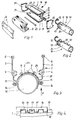
- die wesentlichen Bestandteile eines Airbagmoduls im demontierten Zustand, perspektivisch dargestellt;
- Fig. 2:
- eine abgewandelte Variante des Gasgenerators gegenüber der in Fig. 1 dargestellten;
- Fig. 3:
- einen Schnitt durch das Gehäuse senkrecht zu dessen Längsachse;
- Fig. 4:
- eine Einzelheit bei einer Führungsnut und einer Schiebeleiste als Ansicht in Richtung X nach Fig. 3.
- Fig. 1:
- the essential components of an airbag module in the disassembled state, shown in perspective;
- Fig. 2:
- a modified variant of the gas generator compared to that shown in Fig. 1;
- Fig. 3:
- a section through the housing perpendicular to the longitudinal axis;
- Fig. 4:
- a detail with a guide groove and a sliding bar as a view in the direction X of FIG. 3rd
Ein als Strangpreßprofil gefertigter Grundkörper 1 eines Gehäuses für ein Airbagmodul weist eine nach innen gewölbte Bodenwand 2, zwei Seitenwandteile 3 mit Haltenuten 4 für die Befestigung eines Luftsackes 5 und zwei Haltenuten 6 für die Befestigung einer Abdeckung 7 sowie zur Bodenwand 2 hin zwei Führungsnuten 8 auf. Die Bodenwand 2 ist mit Öffnungen 9 versehen. Ein rohrförmiger Gasgenerator 10 hat entlang seiner Längsachse zwei Schiebeleisten 11, die im montierten Zustand des Airbagmoduls in die Führungsnuten 8 eingeschoben sind, einen elektrischen Anschluß 12 zur Kontaktierung mit einem nicht dargestellten Auslösesensor sowie zur Bodenwand 2 des Grundkörpers 1 hin gerichtete Gasaustrittsöffnungen 13. Die Schiebeleisten 11 können, wie in Fig. 1 dargestellt, als durchgehende Leisten oder, wie in Fig. 2 dargestellt, als gezahnte Schiebeleisten 11' ausgebildet sein. In diesem Fall sind auch die äußeren Schenkel 14 der Führungsnuten 8 in gleicher Weise gezahnt, und zwar so, daß die Zähne 15 der Schiebeleisten 11' durch die Zahnlücken 16 der Schenkel 14 geführt werden können. Eine der Schiebeleisten 11 bzw. 11' hat eine Fixierbohrung 17, an der mittels einer Schraube 18, die in eine Gewindebohrung 19 des Grundkörpers 1 eindrehbar ist, der Gasgenerator 10 gegenüber dem Grundkörper 1 gegen axiales Verschieben gesichert ist.A
An den Stirnseiten ist der Grundkörper 1 mit jeweils einem Deckel 20 versehen, so daß zwischen den Seitenwandteilen 3, der Bodenwand 2 und den Deckeln 20 ein wannenförmiger Raum 21 entsteht. Dieser Raum 21 nimmt den zusammengefalteten Gassack 5 auf. Er ist über die beiden Längsseiten des Grundkörpers 1 mittels Füllerstäben 22 in den Haltenuten 4 gehalten.The
Die Deckel 20 liegen mit einer Rundung 23 an der äußeren Kontur 24 des Gasgenerators 10 an. Zwischen der nach außen weisenden Fläche der Bodenwand 2 des Grundkörpers 1 und der äußeren Kontur 24 des Gasgenerators 10 ist ein im Querschnitt sichelförmiger Raum 25, der an den Stirnseiten mit den an der Kontur 24 des Gasgenerators 10 anliegenden Rundungen 23 der Deckel 20 geschlossen ist. Die Öffnungen 9 verbinden den Raum 25 unterhalb der Bodenwand 2 mit dem Raum 21 oberhalb der Bodenwand 2. Der Airbagmodul ist oberhalb des Gassackes 5 zum Fahrgastraum hin mit der Abdeckung 7 abgeschlossen, die in den Halteelementen 6 fixiert und mit einer Berstnaht 26 versehen ist.The
Beim Aktivieren des Airbags wird vom Auslösesensor über den Anschluß 12 ein Auslösesignal zu dem Gasgenerator 10 geleitet, der durch die Gasaustrittsöffnungen 13 eine Gasmenge in den Raum 25 abgibt. Der sich im Raum 25 aufbauende Druck wird die Schiebeleisten 11, 11' gegen die Schenkel 14 der Führungsnuten 8 pressen, so daß kein Gas unkontrolliert aus dem Raum 25 entweichen kann. Der Druck kann sich im Raum 25 gleichmäßig verteilen und das Gas kann so gleichmäßig durch die Öffnungen 9 der Bodenwand 2 in den Raum 21 gelangen, und zwar unterhalb des in den Haltenuten 4 eingespannten Gassacks 5. Der Gassack 5 bläht sich unter der Wirkung des Gasdruckes auf, sprengt die Berstnaht 26 der Abdeckung 7 und entfaltet sich in den Fahrgastraum des Fahrzeuges hinein.When the airbag is activated, the triggering sensor sends a triggering signal to the
Muß der Gasgenerator 10 vom Grundkörper 1 des Gehäuses entfernt werden, sei es, weil nach dem Aktivwerden des Airbags ein neuer Gasgenerator eingebaut werden soll oder weil der Gasgenerator 10 außerhalb des Fahrzeuges überprüft werden soll, dann muß lediglich die als Sicherungselement dienende Schraube 18 aus der Gewindebohrung 19 entfernt werden, um den Gasgenerator 10 in Richtung seiner Längsachse aus den Führungsnuten 8 heraus ziehen zu können. Der dazu erforderliche Schiebeweg kann kürzer als der Gasgenerator 10 selbst sein und ist abhängig von der Länge der Schiebeleisten 11 bzw. von der Gestaltung der Schiebeleisten 11'. Werden die Schiebeleisten 11' gezahnt ausgeführt und die Schenkel 14 der Führungsnuten 8 mit einer analogen Verzahnung versehen, wie dies beispielhaft in Fig. 2 und Fig. 4 dargestellt ist, dann bedarf es nur eines sehr kurzen Schiebeweges, um den Gasgenerator 10 vom Grundkörper 1 zu trennen.The
Der besondere Vorteil der Erfindung ist darin zu sehen, daß ein Airbagmodul mit einem Gehäuse, dessen Grundkörper 1 als Strangpreßprofil ausgeführt ist, ohne einen besonderen rohrförmigen Raum für den Gasgenerator 10 auskommen kann, so daß damit ein preiswertes Profil ohne rohrförmigen Profilteil und mit geringem Materialeinsatz Verwendung finden kann und der Airbagmodul so leichter als bekannte vergleichbare sind. Darüber hinaus hat ein solcher Airbagmodul Vorteile bei einer im Fahrzeug erforderlichen Entnahme des Gasgenerators 10.The particular advantage of the invention can be seen in the fact that an airbag module with a housing, the
Claims (5)
Applications Claiming Priority (2)
| Application Number | Priority Date | Filing Date | Title |
|---|---|---|---|
| DE4444834A DE4444834A1 (en) | 1994-12-16 | 1994-12-16 | Airbag module |
| DE4444834 | 1994-12-16 |
Publications (2)
| Publication Number | Publication Date |
|---|---|
| EP0716962A1 true EP0716962A1 (en) | 1996-06-19 |
| EP0716962B1 EP0716962B1 (en) | 1999-03-03 |
Family
ID=6535968
Family Applications (1)
| Application Number | Title | Priority Date | Filing Date |
|---|---|---|---|
| EP95119272A Expired - Lifetime EP0716962B1 (en) | 1994-12-16 | 1995-12-07 | Airbag Assembly |
Country Status (3)
| Country | Link |
|---|---|
| EP (1) | EP0716962B1 (en) |
| DE (2) | DE4444834A1 (en) |
| ES (1) | ES2129740T3 (en) |
Cited By (2)
| Publication number | Priority date | Publication date | Assignee | Title |
|---|---|---|---|---|
| EP0767090A1 (en) * | 1995-10-04 | 1997-04-09 | Morton International, Inc. | Passenger airbag inflator with slide in attachment to extruded module |
| EP0769426A3 (en) * | 1995-10-19 | 1999-12-15 | MST Automotive GmbH Automobil-Sicherheitstechnik | Housing for an air bag |
Families Citing this family (5)
| Publication number | Priority date | Publication date | Assignee | Title |
|---|---|---|---|---|
| DE19650268B4 (en) * | 1996-12-04 | 2006-05-04 | Adam Opel Ag | airbag module |
| DE19705099A1 (en) * | 1997-01-31 | 1998-08-06 | Petri Ag | Airbag module especially for use in vehicle |
| DE10347178B4 (en) * | 2003-10-10 | 2007-06-14 | Autoliv Development Ab | Airbag module with an extruded housing and externally supported gas generator |
| DE102004015753B4 (en) * | 2004-03-31 | 2006-09-14 | Autoliv Development Ab | Airbag module with outside-mounted gas generator |
| DE102013005671B4 (en) * | 2013-04-03 | 2016-12-29 | Autoliv Development Ab | airbag module |
Citations (5)
| Publication number | Priority date | Publication date | Assignee | Title |
|---|---|---|---|---|
| DE2061757A1 (en) * | 1970-08-19 | 1972-03-09 | ARA, Ine , West Covina, Cahf (VStA) | Safety air cushion with assemblable inflator |
| US3778085A (en) * | 1971-10-06 | 1973-12-11 | M Lipkin | Concealed pneumatic safety system |
| EP0461757A2 (en) * | 1990-06-15 | 1991-12-18 | Trw Vehicle Safety Systems Inc. | Air bag module construction and assembly technique |
| EP0601489A1 (en) * | 1992-12-08 | 1994-06-15 | Dynamit Nobel Aktiengesellschaft | Liquified gas generator for airbag |
| DE4223237C2 (en) | 1992-07-15 | 1994-10-20 | Daimler Benz Ag | Gas cushion system |
-
1994
- 1994-12-16 DE DE4444834A patent/DE4444834A1/en not_active Withdrawn
-
1995
- 1995-12-07 DE DE59505195T patent/DE59505195D1/en not_active Expired - Lifetime
- 1995-12-07 EP EP95119272A patent/EP0716962B1/en not_active Expired - Lifetime
- 1995-12-07 ES ES95119272T patent/ES2129740T3/en not_active Expired - Lifetime
Patent Citations (5)
| Publication number | Priority date | Publication date | Assignee | Title |
|---|---|---|---|---|
| DE2061757A1 (en) * | 1970-08-19 | 1972-03-09 | ARA, Ine , West Covina, Cahf (VStA) | Safety air cushion with assemblable inflator |
| US3778085A (en) * | 1971-10-06 | 1973-12-11 | M Lipkin | Concealed pneumatic safety system |
| EP0461757A2 (en) * | 1990-06-15 | 1991-12-18 | Trw Vehicle Safety Systems Inc. | Air bag module construction and assembly technique |
| DE4223237C2 (en) | 1992-07-15 | 1994-10-20 | Daimler Benz Ag | Gas cushion system |
| EP0601489A1 (en) * | 1992-12-08 | 1994-06-15 | Dynamit Nobel Aktiengesellschaft | Liquified gas generator for airbag |
Cited By (2)
| Publication number | Priority date | Publication date | Assignee | Title |
|---|---|---|---|---|
| EP0767090A1 (en) * | 1995-10-04 | 1997-04-09 | Morton International, Inc. | Passenger airbag inflator with slide in attachment to extruded module |
| EP0769426A3 (en) * | 1995-10-19 | 1999-12-15 | MST Automotive GmbH Automobil-Sicherheitstechnik | Housing for an air bag |
Also Published As
| Publication number | Publication date |
|---|---|
| ES2129740T3 (en) | 1999-06-16 |
| EP0716962B1 (en) | 1999-03-03 |
| DE4444834A1 (en) | 1996-06-20 |
| DE59505195D1 (en) | 1999-04-08 |
Similar Documents
| Publication | Publication Date | Title |
|---|---|---|
| EP1048531B1 (en) | Side collision protection device for vehicle passengers | |
| DE19712039A1 (en) | Airbag for motor vehicle | |
| EP0942852A1 (en) | Airbag module | |
| WO2022063571A1 (en) | Airbag apparatus for a vehicle seat and vehicle seat having an airbag apparatus | |
| DE4223237A1 (en) | Gas cushion system | |
| EP0716962B1 (en) | Airbag Assembly | |
| EP0769426B1 (en) | Housing for an air bag | |
| DE10354560B4 (en) | Airbag module | |
| DE10356206B4 (en) | Retractor pretensioners combination | |
| DE19801125A1 (en) | Airbag module | |
| DE19720587A1 (en) | Side impact protection device for an occupant of a vehicle | |
| EP0656284B1 (en) | Device for fastening an air bag inside an air bag housing | |
| DE102005028580A1 (en) | Gas bag arrangement for e.g. backrest of vehicle seat, has flexible lug firmly connected with gas bag and partially covering circular or slot-shaped opening that is provided in adjacent area of fastening openings of gas bag | |
| DE102010020341B3 (en) | Side airbag-installation unit for backrest of motor vehicle seat, has inner bag, where free ends of inner bag are connected with trim profile by tear seam | |
| EP1077839B1 (en) | Airbag system with controlled inflation | |
| DE4226316C2 (en) | Occupant restraint system with gas bag and gas generator | |
| DE19859539A1 (en) | Airbag module and manufacturing method has gas distribution pipe with section inside airbag covered by hose, which protects airbag material during pipe insertion | |
| DE19909426B4 (en) | airbag unit | |
| DE10339523B4 (en) | Airbag module with gas generator and with at least one sleeve-shaped mass flow distributor | |
| DE102007046822A1 (en) | Combustion chamber assembly for an airbag module | |
| DE10200848A1 (en) | Side air bag module for motor vehicle has ramp for air bag in casing attached to side upholstery of vehicle | |
| EP1088711A2 (en) | Passenger side air bag module for a motor vehicle | |
| DE10159024C1 (en) | Automobile passenger airbag module has retention device fixing gas generator and gas sack in module housing | |
| DE10211061A1 (en) | Side-mounted airbag module for use in car has gas feed pipe with side exit extending into gas bag and blowing gas into second chamber through side exit | |
| DE10328562A1 (en) | Airbag module for vehicles, comprises a single-jet tube, which penetrates the gas generator and guides pressure gas from gas generator into gas conducting duct |
Legal Events
| Date | Code | Title | Description |
|---|---|---|---|
| PUAI | Public reference made under article 153(3) epc to a published international application that has entered the european phase |
Free format text: ORIGINAL CODE: 0009012 |
|
| AK | Designated contracting states |
Kind code of ref document: A1 Designated state(s): DE ES FR GB |
|
| 17P | Request for examination filed |
Effective date: 19960923 |
|
| GRAG | Despatch of communication of intention to grant |
Free format text: ORIGINAL CODE: EPIDOS AGRA |
|
| GRAG | Despatch of communication of intention to grant |
Free format text: ORIGINAL CODE: EPIDOS AGRA |
|
| GRAH | Despatch of communication of intention to grant a patent |
Free format text: ORIGINAL CODE: EPIDOS IGRA |
|
| 17Q | First examination report despatched |
Effective date: 19980610 |
|
| GRAH | Despatch of communication of intention to grant a patent |
Free format text: ORIGINAL CODE: EPIDOS IGRA |
|
| GRAA | (expected) grant |
Free format text: ORIGINAL CODE: 0009210 |
|
| AK | Designated contracting states |
Kind code of ref document: B1 Designated state(s): DE ES FR GB |
|
| REF | Corresponds to: |
Ref document number: 59505195 Country of ref document: DE Date of ref document: 19990408 |
|
| ET | Fr: translation filed | ||
| GBT | Gb: translation of ep patent filed (gb section 77(6)(a)/1977) |
Effective date: 19990514 |
|
| REG | Reference to a national code |
Ref country code: ES Ref legal event code: FG2A Ref document number: 2129740 Country of ref document: ES Kind code of ref document: T3 |
|
| PLBE | No opposition filed within time limit |
Free format text: ORIGINAL CODE: 0009261 |
|
| STAA | Information on the status of an ep patent application or granted ep patent |
Free format text: STATUS: NO OPPOSITION FILED WITHIN TIME LIMIT |
|
| 26N | No opposition filed | ||
| REG | Reference to a national code |
Ref country code: GB Ref legal event code: IF02 |
|
| REG | Reference to a national code |
Ref country code: GB Ref legal event code: 732E Free format text: REGISTERED BETWEEN 20090219 AND 20090225 |
|
| REG | Reference to a national code |
Ref country code: GB Ref legal event code: 732E Free format text: REGISTERED BETWEEN 20090305 AND 20090311 |
|
| REG | Reference to a national code |
Ref country code: GB Ref legal event code: 732E Free format text: REGISTERED BETWEEN 20091029 AND 20091104 |
|
| REG | Reference to a national code |
Ref country code: GB Ref legal event code: 732E Free format text: REGISTERED BETWEEN 20091105 AND 20091111 |
|
| REG | Reference to a national code |
Ref country code: DE Ref legal event code: R081 Ref document number: 59505195 Country of ref document: DE Owner name: GM GLOBAL TECHNOLOGY OPERATIONS LLC (N. D. GES, US Free format text: FORMER OWNER: GM GLOBAL TECHNOLOGY OPERATIONS, INC., DETROIT, MICH., US Effective date: 20110323 |
|
| PGFP | Annual fee paid to national office [announced via postgrant information from national office to epo] |
Ref country code: DE Payment date: 20121205 Year of fee payment: 18 |
|
| PGFP | Annual fee paid to national office [announced via postgrant information from national office to epo] |
Ref country code: ES Payment date: 20121227 Year of fee payment: 18 Ref country code: GB Payment date: 20121205 Year of fee payment: 18 |
|
| PGFP | Annual fee paid to national office [announced via postgrant information from national office to epo] |
Ref country code: FR Payment date: 20130107 Year of fee payment: 18 |
|
| REG | Reference to a national code |
Ref country code: DE Ref legal event code: R119 Ref document number: 59505195 Country of ref document: DE |
|
| GBPC | Gb: european patent ceased through non-payment of renewal fee |
Effective date: 20131207 |
|
| REG | Reference to a national code |
Ref country code: FR Ref legal event code: ST Effective date: 20140829 |
|
| REG | Reference to a national code |
Ref country code: DE Ref legal event code: R119 Ref document number: 59505195 Country of ref document: DE Effective date: 20140701 |
|
| PG25 | Lapsed in a contracting state [announced via postgrant information from national office to epo] |
Ref country code: DE Free format text: LAPSE BECAUSE OF NON-PAYMENT OF DUE FEES Effective date: 20140701 |
|
| PG25 | Lapsed in a contracting state [announced via postgrant information from national office to epo] |
Ref country code: GB Free format text: LAPSE BECAUSE OF NON-PAYMENT OF DUE FEES Effective date: 20131207 Ref country code: FR Free format text: LAPSE BECAUSE OF NON-PAYMENT OF DUE FEES Effective date: 20131231 |
|
| REG | Reference to a national code |
Ref country code: ES Ref legal event code: FD2A Effective date: 20150331 |
|
| PG25 | Lapsed in a contracting state [announced via postgrant information from national office to epo] |
Ref country code: ES Free format text: LAPSE BECAUSE OF NON-PAYMENT OF DUE FEES Effective date: 20131208 |