EP0716461A1 - Electronic Appliance housing having storage portion - Google Patents
Electronic Appliance housing having storage portion Download PDFInfo
- Publication number
- EP0716461A1 EP0716461A1 EP95308592A EP95308592A EP0716461A1 EP 0716461 A1 EP0716461 A1 EP 0716461A1 EP 95308592 A EP95308592 A EP 95308592A EP 95308592 A EP95308592 A EP 95308592A EP 0716461 A1 EP0716461 A1 EP 0716461A1
- Authority
- EP
- European Patent Office
- Prior art keywords
- cover
- housing
- locking
- electronic appliance
- engaging
- Prior art date
- Legal status (The legal status is an assumption and is not a legal conclusion. Google has not performed a legal analysis and makes no representation as to the accuracy of the status listed.)
- Granted
Links
- 230000000994 depressogenic effect Effects 0.000 abstract description 10
- 230000000694 effects Effects 0.000 abstract description 6
- 230000000881 depressing effect Effects 0.000 description 5
- 230000005489 elastic deformation Effects 0.000 description 1
- 238000000034 method Methods 0.000 description 1
- 230000004048 modification Effects 0.000 description 1
- 238000012986 modification Methods 0.000 description 1
- 230000000717 retained effect Effects 0.000 description 1
Images



Classifications
-
- H—ELECTRICITY
- H04—ELECTRIC COMMUNICATION TECHNIQUE
- H04B—TRANSMISSION
- H04B1/00—Details of transmission systems, not covered by a single one of groups H04B3/00 - H04B13/00; Details of transmission systems not characterised by the medium used for transmission
- H04B1/38—Transceivers, i.e. devices in which transmitter and receiver form a structural unit and in which at least one part is used for functions of transmitting and receiving
- H04B1/3827—Portable transceivers
- H04B1/3883—Arrangements for mounting batteries or battery chargers
-
- Y—GENERAL TAGGING OF NEW TECHNOLOGICAL DEVELOPMENTS; GENERAL TAGGING OF CROSS-SECTIONAL TECHNOLOGIES SPANNING OVER SEVERAL SECTIONS OF THE IPC; TECHNICAL SUBJECTS COVERED BY FORMER USPC CROSS-REFERENCE ART COLLECTIONS [XRACs] AND DIGESTS
- Y10—TECHNICAL SUBJECTS COVERED BY FORMER USPC
- Y10T—TECHNICAL SUBJECTS COVERED BY FORMER US CLASSIFICATION
- Y10T292/00—Closure fasteners
- Y10T292/08—Bolts
- Y10T292/0911—Hooked end
- Y10T292/0945—Operating means
- Y10T292/0948—Closure
Definitions
- the present invention relates generally to the structure of the housing of an electronic appliance. More specifically, the present invention is directed to the structure of a detachable cover used to close a storage portion of a housing, used for storing an electronic part such as a battery.
- compartments for storing electric batteries or cells are formed in the housings. Batteries are mounted in the battery storage portion, and an opening for this battery storage portion is covered by a cover.
- a locking mechanism is normally provided in order that the cover, when attached, does not fall off the housing.
- the locking mechanism is constructed of, for example, a locking groove provided at the housing side, and a locking piece engaging with this locking groove and mounted on the cover.
- Japanese Laid-Open Patent No. Hei 1-260757 discloses a technique for preventing the cover from falling off by employing such a locking piece.
- a preferred embodiment of the invention takes the form of an electronic appliance housing which is constructed with a cover having a locking groove, and an operation portion with a locking portion which engages this locking groove, and a housing with a portion mounting the operation portion and a cover mounting portion to which the cover is attached.
- the cover is slidably mounted on the housing.
- the locking groove of the cover and/or the locking portion have portions which are inclined with respect to the cover in this structure.
- the operation portion has a portion which is slidable along a direction perpendicular to the sliding direction of the cover. With the aid of this sliding portion, the locking portion is slidably entered into and removed from the locking groove.
- the cover is fixed so as not to be able to fall off.
- parallelogram shapes may be employed.
- the operation portion has a structure such that this operation portion is moveable downwardly in response to the depression of the housing applied from the upper direction.
- the operation portion is mounted on a mounting portion of the housing which is elastically deformable, so that the operation portion can be moved downwardly, that is, in the direction perpendicular to the directions of sliding of the cover and of the locking portion.
- the locking portion engaging the locking groove of the cover is also moved to a lower position.
- a leaf spring or a coil spring may be arranged between the operation portion and the housing, the operation portion may be moved downwardly by depression against the spring.
- an engaging piece and an engaging projection portion are provided respectively on the cover and the housing mount portion to retain the cover on the housing.
- An engaging piece is also formed at a tip portion of the cover along the sliding direction, and engages with an engaging hole formed in the housing when the cover is completely mounted on the housing.
- the engaging piece of the cover has a pawl. When engaged the pawl enters the engaging hole in the housing and is held by the projection portion at the housing side, and thus the cover is not liable to fall out of the housing.
- a spring portion may be provided in such a manner that the cover is biased upwardly.
- the cover when the cover is removed by depression of the operation portion, the cover is also depressed downwardly as the operation portion is depressed along the lower direction, so that the pawl is automatically released from the projection portion of the engaging hole. Therefore, the pawl may be released from the housing and the cover may be slid along the removing direction by depressing the operation portion downwardly.
- FIG 1 schematically shows the structure of an electronic appliance housing containing a known locking mechanism.
- a radio paging receiver is employed as an example.
- a rectangular opening 21a is formed in a rear surface of a housing 21 of this radio paging receiver.
- a battery storage chamber 22 is defined within the housing 21.
- a cover 23 used to close this opening 21a is formed in a rectangular shape whose one end portion is bent, and a rib 24 is formed in a standing condition along both side edge portions thereof.
- Engage pieces 25 are fabricated on the ribs 24 and project outwardly on both sides.
- a locking groove 26 is formed in a portion of one rib 24. Further, another engage piece 27 whose tip portion is wedge-shaped is formed on the other end portion of the cover 23.
- engage projection portions 28 engaged with the engage piece 25 of the cover 23 are provided at both sides of the opening 21a of the housing 21.
- An engage hole 29 is made in an end face of the opening 21a, and this opening 21a is covered by the above-described cover 23. Since the cover 23 is slightly slid along the longitudinal direction thereof, the engage piece 25 is engaged with the engage projection portion 28. The engage piece 27 is engaged with the engage hole 29. With this engagement, the cover 23 is held by the housing 21.
- a slide groove 30 is formed in one side of the opening 21a toward a direction perpendicular to this side surface. Within this slide groove 30, a locking piece 31 is installed which can be slid along the same direction as the above-described direction.
- This locking piece 31 is operable with an operation portion exposed toward the outer surface of the housing by manual manipulation.
- a locking portion 33 of the tip portion thereof is inserted into the above-described locking groove 26 of the cover 28.
- the locking portion 33 can be withdrawn from the locking groove 26.
- the cover 23 can be removed from the housing 21 to thereby open the opening 21a, so that the battery may be removed and replaced.
- the locking piece 31 when the locking arrangement is released from the condition under which the locking portion 33 is fitted into the locking groove 26 in order to remove the cover 23 mounted on the opening 21a, the locking piece 31 cannot be smoothly slid along into the lock-released condition. This is because the large slide force of the locking piece 31 is maintained due to contact friction occurring between the locking portion 33 and the locking groove 26.
- Figure 2 is a perspective view showing the cover removed from the electronic appliance housing according to one embodiment of the present invention. Also, a radio paging receiver is employed as an example of this electronic appliance in this embodiment.
- a rectangular opening 1a is formed in a rear surface of the housing 1 of this radio paging receiver.
- a battery storage chamber 2 is defined within the housing 1.
- a cover 3 used to close this opening 1a is formed in a rectangular shape whose one end portion is bent, and a rib 4 is formed in a standing condition along both side edge portions thereof.
- Engage pieces 5 are fabricated on the ribs 4 and project outwardly on both sides.
- a locking groove 6 is formed in a portion of one rib 4. Further, another engage piece 7 whose tip portion is wedge-shaped is formed on the other end portion of the cover 3.
- the locking groove 6 is made of a notch having the shape of a parallelogram (as will be discussed later).
- engage projection portions 8 engaged with the engage piece 5 of the cover 3 are provided at both sides of the opening 1a of the housing 1.
- An engage hole 9 is made in an end face of the opening 1a.
- a slide portion 10 constructed of a rectangular concave portion is formed in one side of the opening 1a along a direction perpendicular to this side surface.
- a locking piece 11 is slidably provided within this slide portion 10 for movement along the same direction as the above-described direction.
- FIG 3 is a fragmentary perspective view showing the detailed structure of the slide portion 10, a portion of which is broken away.
- a slit 12 is opened along the slide direction in a bottom surface of the slide portion 10 formed in the housing 1.
- the locking piece 11 has a small piece portion 13 which penetrates through this slit 12, an operation portion 14 integrally formed on the upper portion thereof, and a locking portion 15 integrally formed on the lower portion thereof.
- the sectional shape of the locking portion 15 is made as a parallelogram corresponding to the above-described locking groove 6. It should be understood that although the parallelogram-shaped portion is formed as a complete notch groove in this embodiment, this parallelogram-shaped portion can form only a partial groove so long as an inclined portion is provided (the notch need not extend through the whole thickness of the rib 4).
- the slide portion 10 formed in the housing 1 has a notch slit 16 formed along both sides of this slide portion 10.
- the slide portion 10 is supported at one edge portion 10a with respect to the rest of the housing 1. While this supported edge portion 10a is used as a fulcrum, elastic deformation can be achieved along the thickness direction of the housing 1, namely, the upper/lower direction of Figure 3.
- the locking piece 11 can be slid from the opening 1a to the withdrawn position in a similar manner to the known structure. Then, while the cover 3 is slid with respect to the opening 1a by utilizing the rib 4 of the cover 3, the cover 3 is inserted. As a result, as illustrated in Figure 4, the engaging piece 5 is engaged with the engaging projection portion 8, and also the engaging piece 7 is engaged with the engaging hole 9. Then the locking piece 11 is slid toward the opening 1a, the locking portion 15 is engaged into the locking groove 6, and the cover 3 is brought into the fixed condition with respect to the housing 1, so that it is possible to avoid the cover 3 from falling off the opening 1a.
- the cover 3 when the cover 3 is to be removed from the opening 1a, the locking piece 11 is moved in the direction away from the opening 1a, so that the locking portion 15 is withdrawn from the locking groove 6.
- the cover 3 can be removed from the opening 1a by performing a similar operation to the known manner.
- the locking condition may be released by depressing the locking piece 11 downwardly while the locking portion 15 still engages the locking groove 6.
- the slide portion 10 for supporting the locking piece 11 is elastically deformed downwardly, with one edge portion 10a thereof being used as a fulcrum.
- both the slide portion 10 and the locking piece 11 are elastically deformed downwardly as an integral unit, the inclined edge portions of the locking portion 15 and the locking groove 6, which are in the form of parallelograms, are brought into an abutting condition.
- both of the locking piece 11 and the operation portion 14 can be made compact because of the arranging space relationship in the housing 1.
- the sliding operation of the locking piece 11 is no longer necessary when the locking condition is to be released, in which the operation was difficult. Rather, the locking condition can be released only by merely depressing the locking piece 11, resulting in very easy operation.
- Figure 7 is a perspective view showing the cover removed in the electronic appliance housing according to another embodiment of the present invention.
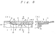
- Figure 8 shows at (a) a cross-sectional view representing such a condition that a lock releasing operation by a locking piece is accomplished and at (b) a sectional view thereof, taken along a line C-C of (a).
- the structure shown in Figure 7 is substantially identical to the above-explained structure indicated in Figure 2. A difference between them is that, in the structure shown in Figure 7, a spring 17 used to push the cover upwardly is provided in a bottom portion 19 of the housing to which the cover is mounted. In this case, as one example of the spring 17, there is shown a leaf spring embedded in the bottom of the housing.
- the spring 17 When the cover 3 is to be mounted on the housing 1 by the sliding operation, the spring 17 is depressed downwardly. Once the cover 3 is mounted on the housing 1, a pawl 18 of the engaging piece 7 of the cover 3 enters into the engaging hole 9 of the housing 1, so that the cover 3 is retained. Since the cover 3 is pushed upwardly by the spring 17, the upper surface of the engaging piece 5 of the cover 3 is strongly in contact with the lower surface of the engaging projection portion 8 of the housing 1. With this contact, even when the housing 1 is vibrated, there is no possibility that the cover 3 would be vibrated.
- the cover Since the spring is employed so as to push up the cover to the housing side, the cover is not easily removed from the housing, but also is not swung even under vibrations. Even if such a structure is employed, the cover can when desired be simply released from the housing by depressing the operation portion.
- the present invention is not limited to these embodiments, but may be similarly applied to a portable transceivers or telephones, and other electronic appliances. Also, in these embodiments, the present invention can be applied to battery covers. Alternatively, the present invention may be similarly applied to such a cover structure for closing an opening which is used to store an attachment part in the housing.
- the edge portions inclined along the cover sliding direction are formed in the locking portion and on the locking piece for bringing the cover into the locking condition, and also engaging the locking portion into the locking groove.
- the locking piece is supported in such a manner that this locking piece can be slid on a portion of the housing, and this portion of the housing may be elastically deformed in combination with the locking piece along the plate thickness direction of the housing by way of the slit formed around this portion.
- the locking piece may be elastically deformed toward the inside of the housing.
- both of the locking piece and a portion of the housing are elastically deformed by a preselected amount, it is so constructed that the locking portion is released from the notch edge of the locking groove and moves outside this locking groove. Therefore, when the locking piece is elastically deformed by a preselected amount, the engaging condition between the locking portion and the locking groove is released, without sliding the locking piece, so that the cover may be removed.
Landscapes
- Engineering & Computer Science (AREA)
- Computer Networks & Wireless Communication (AREA)
- Signal Processing (AREA)
- Casings For Electric Apparatus (AREA)
- Battery Mounting, Suspending (AREA)
Abstract
Description
- The present invention relates generally to the structure of the housing of an electronic appliance. More specifically, the present invention is directed to the structure of a detachable cover used to close a storage portion of a housing, used for storing an electronic part such as a battery.
- In portable telephones, radio paging receivers and other electronic appliances, compartments for storing electric batteries or cells are formed in the housings. Batteries are mounted in the battery storage portion, and an opening for this battery storage portion is covered by a cover.
- When the battery is taken out from the housing, the cover is removed from the housing, and the cover is reattached after the battery is re-inserted. Since the battery is replaced at a certain frequency, it is required that the cover can be simply detached from the housing. A locking mechanism is normally provided in order that the cover, when attached, does not fall off the housing. The locking mechanism is constructed of, for example, a locking groove provided at the housing side, and a locking piece engaging with this locking groove and mounted on the cover. For instance, Japanese Laid-Open Patent No. Hei 1-260757 discloses a technique for preventing the cover from falling off by employing such a locking piece.
- However, since the component space within the conventional housing structure is limited, it is rather difficult to define a sufficiently large space to accommodate the locking piece. As a consequence, both the locking piece and the portion for operating it are necessarily made compact, so that the operability of the locking piece is poorer. Therefore, a strong force cannot easily be applied to the locking piece, so that the operations of removing and replacing the cover become difficult.
- In particular, when the locking mechanism is to be released from the condition in which the locking piece is fitted into the locking groove, in order to remove the cover mounted on the opening, the locking piece cannot be smoothly slid along to the lock-released condition. This is because contact friction is produced between the locking piece and the locking groove.
- If a space (or 'play') were made between the locking piece and the locking groove when the cover is mounted on the housing, then the cover cannot be sufficiently fixed, and as a result, when the housing itself is vibrated, the cover would also vibrate.
- The present invention is defined in
claim 1 below, to which reference should now be made. Advantageous features of the invention are set forth in the appendant claims. - A preferred embodiment of the invention is described in more detail below and takes the form of an electronic appliance housing which is constructed with a cover having a locking groove, and an operation portion with a locking portion which engages this locking groove, and a housing with a portion mounting the operation portion and a cover mounting portion to which the cover is attached. The cover is slidably mounted on the housing. The locking groove of the cover and/or the locking portion have portions which are inclined with respect to the cover in this structure. The operation portion has a portion which is slidable along a direction perpendicular to the sliding direction of the cover. With the aid of this sliding portion, the locking portion is slidably entered into and removed from the locking groove. When the locking portion is fitted into the locking groove with the cover mounted on the housing, the cover is fixed so as not to be able to fall off. As possible sectional shapes of the above-explained locking groove and locking portion, parallelogram shapes may be employed.
- Furthermore, the operation portion has a structure such that this operation portion is moveable downwardly in response to the depression of the housing applied from the upper direction. The operation portion is mounted on a mounting portion of the housing which is elastically deformable, so that the operation portion can be moved downwardly, that is, in the direction perpendicular to the directions of sliding of the cover and of the locking portion. When the operation portion is depressed downwardly, the locking portion engaging the locking groove of the cover is also moved to a lower position. It should be noted that since a leaf spring or a coil spring may be arranged between the operation portion and the housing, the operation portion may be moved downwardly by depression against the spring.
- When the locking piece in the locking state is moved downwardly by depressing the operation portion, a wedge or cam effect is produced by an abutment force exerted between the locking portion and an inclined edge located opposite in the locking groove. Only one of these engaging surfaces need be inclined. The cover is slid along the removal direction in response to the force produced by this wedge effect. As a consequence, when the cover is removed, the cover can be simply taken out from the housing without the need for sliding operation of the locking piece. Therefore, even when the locking piece is made compact, the operability thereof does not suffer.
- Moreover, in the electronic appliance housing of the above-described structure, an engaging piece and an engaging projection portion are provided respectively on the cover and the housing mount portion to retain the cover on the housing. An engaging piece is also formed at a tip portion of the cover along the sliding direction, and engages with an engaging hole formed in the housing when the cover is completely mounted on the housing. The engaging piece of the cover has a pawl. When engaged the pawl enters the engaging hole in the housing and is held by the projection portion at the housing side, and thus the cover is not liable to fall out of the housing.
- A spring portion may be provided in such a manner that the cover is biased upwardly. With such a structure, the engaging piece of the cover is pressed against the engaging projection portion of the housing when the cover is mounted on the housing. As a consequence, even when vibrations are externally applied, the cover is not vibrated.
- On the other hand, when the cover is removed by depression of the operation portion, the cover is also depressed downwardly as the operation portion is depressed along the lower direction, so that the pawl is automatically released from the projection portion of the engaging hole. Therefore, the pawl may be released from the housing and the cover may be slid along the removing direction by depressing the operation portion downwardly.
- The present invention is described in more detail in the following detailed description taken in conjunction with the accompanying drawings, wherein:
- Figure 1 is a perspective view for showing a known housing from which the cover is removed;
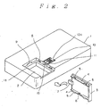
- Figure 2 is a perspective view for indicating an electronic appliance housing from which the cover is removed, according to an embodiment of the present invention;
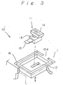
- Figure 3 is a fragmentary perspective view representing the detailed structure of a slide portion of the electronic appliance housing shown in Figure 2;
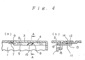
- Figure 4 shows at (a) a cross-sectional view showing the locked condition of a locking piece employed in the housing of Figure 2, and at (b) a sectional view thereof, taken along a line A-A of (a);
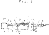
- Figure 5 shows at (a) a cross-sectional view indicating a lock release operation by the locking piece, and at (b) a sectional view for showing the locking release operation, taken along a line B-B of (a);
- Figure 6 shows at (a) a cross-sectional view for showing the condition of completion of the locking release operation by the locking piece, and at (b) a sectional view thereof, taken along line C-C of (a);
- Figure 7 is a perspective view representing an electronic appliance housing from which the cover is removed, according to another embodiment of the present invention; and
- Figure 8 is a cross-sectional view indicating the condition of completion of a locking release operation by a locking piece employed in the electronic appliance housing of Figure 7.
- Before describing the structure of an electronic appliance housing according to the present invention, the structure of a known electronic appliance housing will now be explained for a better understanding of the present inventive idea.
- Figure 1 schematically shows the structure of an electronic appliance housing containing a known locking mechanism. In this prior art, a radio paging receiver is employed as an example. In Figure 1, a
rectangular opening 21a is formed in a rear surface of ahousing 21 of this radio paging receiver. As viewed into this opening 21a, abattery storage chamber 22 is defined within thehousing 21. - A
cover 23 used to close this opening 21a is formed in a rectangular shape whose one end portion is bent, and arib 24 is formed in a standing condition along both side edge portions thereof.Engage pieces 25 are fabricated on theribs 24 and project outwardly on both sides. Alocking groove 26 is formed in a portion of onerib 24. Further, another engagepiece 27 whose tip portion is wedge-shaped is formed on the other end portion of thecover 23. - Also, engage
projection portions 28 engaged with the engagepiece 25 of thecover 23 are provided at both sides of the opening 21a of thehousing 21. An engagehole 29 is made in an end face of the opening 21a, and this opening 21a is covered by the above-describedcover 23. Since thecover 23 is slightly slid along the longitudinal direction thereof, the engagepiece 25 is engaged with theengage projection portion 28. The engagepiece 27 is engaged with the engagehole 29. With this engagement, thecover 23 is held by thehousing 21. - A
slide groove 30 is formed in one side of theopening 21a toward a direction perpendicular to this side surface. Within thisslide groove 30, a lockingpiece 31 is installed which can be slid along the same direction as the above-described direction. - This locking
piece 31 is operable with an operation portion exposed toward the outer surface of the housing by manual manipulation. When the lockingpiece 31 is slid toward the opening, a lockingportion 33 of the tip portion thereof is inserted into the above-describedlocking groove 26 of thecover 28. Thus, there is protection against thecover 23 being removed from thehousing 21. Accordingly, when the lockingpiece 31 is manually manipulated along the reverse direction, the lockingportion 33 can be withdrawn from the lockinggroove 26. As a result, thecover 23 can be removed from thehousing 21 to thereby open theopening 21a, so that the battery may be removed and replaced. - Normally, since a compact electronic appliance is required, it is rather difficult to define a sufficiently large space to accommodate the
locking piece 31. As a consequence, since the lockingpiece 31 and the operation portion become small, the operability of the lockingpiece 31 would be made poorer, and also a strong force cannot be easily applied to thelocking piece 31. Thus, the operations when thecover 23 is mounted and removed become difficult. - Especially, in the known structure, when the locking arrangement is released from the condition under which the locking
portion 33 is fitted into the lockinggroove 26 in order to remove thecover 23 mounted on theopening 21a, the lockingpiece 31 cannot be smoothly slid along into the lock-released condition. This is because the large slide force of the lockingpiece 31 is maintained due to contact friction occurring between the lockingportion 33 and the lockinggroove 26. - Referring now to the remaining drawings, an electronic appliance housing according to an embodiment of the present invention will be explained. Figure 2 is a perspective view showing the cover removed from the electronic appliance housing according to one embodiment of the present invention. Also, a radio paging receiver is employed as an example of this electronic appliance in this embodiment.
- In Figure 2, a rectangular opening 1a is formed in a rear surface of the
housing 1 of this radio paging receiver. As viewed into this opening 1a, abattery storage chamber 2 is defined within thehousing 1. Acover 3 used to close this opening 1a is formed in a rectangular shape whose one end portion is bent, and arib 4 is formed in a standing condition along both side edge portions thereof. Engagepieces 5 are fabricated on theribs 4 and project outwardly on both sides. A lockinggroove 6 is formed in a portion of onerib 4. Further, another engagepiece 7 whose tip portion is wedge-shaped is formed on the other end portion of thecover 3. The lockinggroove 6 is made of a notch having the shape of a parallelogram (as will be discussed later). - Also, engage
projection portions 8 engaged with the engagepiece 5 of thecover 3 are provided at both sides of the opening 1a of thehousing 1. An engagehole 9 is made in an end face of the opening 1a. - When the
cover 3 is put in place, the opening 1a is covered by thiscover 3 and then thecover 3 is slightly slid along the longitudinal direction of thecover 3. As a result, the engagepieces 5 are engaged with the engageprojection portions 8, and the engagepiece 7 is engaged with the engagehole 9. With these engagements, thecover 3 is held by thehousing 1. - A
slide portion 10 constructed of a rectangular concave portion is formed in one side of the opening 1a along a direction perpendicular to this side surface. A lockingpiece 11 is slidably provided within thisslide portion 10 for movement along the same direction as the above-described direction. - Figure 3 is a fragmentary perspective view showing the detailed structure of the
slide portion 10, a portion of which is broken away. Aslit 12 is opened along the slide direction in a bottom surface of theslide portion 10 formed in thehousing 1. The lockingpiece 11 has asmall piece portion 13 which penetrates through thisslit 12, anoperation portion 14 integrally formed on the upper portion thereof, and a lockingportion 15 integrally formed on the lower portion thereof. Then, the sectional shape of the lockingportion 15 is made as a parallelogram corresponding to the above-describedlocking groove 6. It should be understood that although the parallelogram-shaped portion is formed as a complete notch groove in this embodiment, this parallelogram-shaped portion can form only a partial groove so long as an inclined portion is provided (the notch need not extend through the whole thickness of the rib 4). - In this example, the
slide portion 10 formed in thehousing 1 has a notch slit 16 formed along both sides of thisslide portion 10. As a result of this slit 16, theslide portion 10 is supported at oneedge portion 10a with respect to the rest of thehousing 1. While this supportededge portion 10a is used as a fulcrum, elastic deformation can be achieved along the thickness direction of thehousing 1, namely, the upper/lower direction of Figure 3. - With this structure, when the
cover 3 is to be mounted on the opening 1a of thehousing 1, the lockingpiece 11 can be slid from the opening 1a to the withdrawn position in a similar manner to the known structure. Then, while thecover 3 is slid with respect to the opening 1a by utilizing therib 4 of thecover 3, thecover 3 is inserted. As a result, as illustrated in Figure 4, the engagingpiece 5 is engaged with the engagingprojection portion 8, and also theengaging piece 7 is engaged with the engaginghole 9. Then the lockingpiece 11 is slid toward the opening 1a, the lockingportion 15 is engaged into the lockinggroove 6, and thecover 3 is brought into the fixed condition with respect to thehousing 1, so that it is possible to avoid thecover 3 from falling off the opening 1a. - On the other hand, when the
cover 3 is to be removed from the opening 1a, the lockingpiece 11 is moved in the direction away from the opening 1a, so that the lockingportion 15 is withdrawn from the lockinggroove 6. Thus, thecover 3 can be removed from the opening 1a by performing a similar operation to the known manner. - Alternatively, the locking condition may be released by depressing the locking
piece 11 downwardly while the lockingportion 15 still engages the lockinggroove 6. As shown in Figure 5 in the cross-sectional view (a) and the sectional view (b) taken along the line B-B of (a), when the lockingpiece 11 is depressed downwardly, theslide portion 10 for supporting the lockingpiece 11 is elastically deformed downwardly, with oneedge portion 10a thereof being used as a fulcrum. At this time, since both theslide portion 10 and thelocking piece 11 are elastically deformed downwardly as an integral unit, the inclined edge portions of the lockingportion 15 and the lockinggroove 6, which are in the form of parallelograms, are brought into an abutting condition. In response to the wedge force exerted by the wedge effect of the inclined edge portions, therib 4 in which the lockinggroove 6 is formed, and thus thecover 3, is pushed out along the X direction as seen in Figure 5 at (a). Thus thecover 3 is moved along the removal direction by this operation; the engagepiece 7 is released from the engaging condition established with the engaginghole 9. - Furthermore, when the locking
piece 11 is depressed downwardly, as shown in Figure 6 in the cross-sectional view (a) and the sectional view (b) taken along a line C-C of (a), thecover 3 is transported along the X direction as indicated by an arrow by a distance equivalent to the longitudinal length of the inclined edge thereof. The engaging condition between theengaging piece 5 and the engagingprojection portion 8 is also released. Thus, the lockingportion 15 is completely removed from the lockinggroove 6. When thecover 3 is withdrawn under this condition, thecover 3 can be simply removed from thehousing 1. - As a consequence, in this structure, both of the locking
piece 11 and theoperation portion 14 can be made compact because of the arranging space relationship in thehousing 1. The sliding operation of the lockingpiece 11 is no longer necessary when the locking condition is to be released, in which the operation was difficult. Rather, the locking condition can be released only by merely depressing the lockingpiece 11, resulting in very easy operation. - Next, an electronic appliance housing according to another embodiment of the present invention will now be explained with reference to Figures 7 and 8. Figure 7 is a perspective view showing the cover removed in the electronic appliance housing according to another embodiment of the present invention. Figure 8 shows at (a) a cross-sectional view representing such a condition that a lock releasing operation by a locking piece is accomplished and at (b) a sectional view thereof, taken along a line C-C of (a).
- The structure shown in Figure 7 is substantially identical to the above-explained structure indicated in Figure 2. A difference between them is that, in the structure shown in Figure 7, a
spring 17 used to push the cover upwardly is provided in abottom portion 19 of the housing to which the cover is mounted. In this case, as one example of thespring 17, there is shown a leaf spring embedded in the bottom of the housing. - When the
cover 3 is to be mounted on thehousing 1 by the sliding operation, thespring 17 is depressed downwardly. Once thecover 3 is mounted on thehousing 1, apawl 18 of theengaging piece 7 of thecover 3 enters into the engaginghole 9 of thehousing 1, so that thecover 3 is retained. Since thecover 3 is pushed upwardly by thespring 17, the upper surface of theengaging piece 5 of thecover 3 is strongly in contact with the lower surface of the engagingprojection portion 8 of thehousing 1. With this contact, even when thehousing 1 is vibrated, there is no possibility that thecover 3 would be vibrated. - On the other hand, when the
cover 3 is to be removed by the depression of theoperation portion 14, as illustrated at (a) in Figure 8, thecover 3 is similarly depressed along the direction indicated by arrows Y. Consequently, thepawl 18 of theengaging piece 7 is automatically released from the engaginghole 9 of thehousing 1. Then, as described above, force is exerted on thecover 3 along the removal direction, so that thecover 3 is slid to be taken out from thehousing 1. - Since the spring is employed so as to push up the cover to the housing side, the cover is not easily removed from the housing, but also is not swung even under vibrations. Even if such a structure is employed, the cover can when desired be simply released from the housing by depressing the operation portion.
- The above-described embodiments are examples of the application of the present invention to radio paging receivers. However, the present invention is not limited to these embodiments, but may be similarly applied to a portable transceivers or telephones, and other electronic appliances. Also, in these embodiments, the present invention can be applied to battery covers. Alternatively, the present invention may be similarly applied to such a cover structure for closing an opening which is used to store an attachment part in the housing.
- As previously described, the edge portions inclined along the cover sliding direction are formed in the locking portion and on the locking piece for bringing the cover into the locking condition, and also engaging the locking portion into the locking groove. When the locking piece under locking state is depressed to be elastically deformed, the force exerted from the wedge effect is produced by receiving the abutting force produced between the locking portion and the inclined portion opposite on the locking groove. As a consequence, the cover can be removed by being slid. Accordingly, when the cover is removed, the locking piece does not need to be slid. Even when the locking piece is made compact, the operability to detach the cover can be improved.
- In particular, the locking piece is supported in such a manner that this locking piece can be slid on a portion of the housing, and this portion of the housing may be elastically deformed in combination with the locking piece along the plate thickness direction of the housing by way of the slit formed around this portion. As a result, the locking condition can be maintained while the locking piece is supported on the housing. On the other hand, the locking piece may be elastically deformed toward the inside of the housing.
- When both of the locking piece and a portion of the housing are elastically deformed by a preselected amount, it is so constructed that the locking portion is released from the notch edge of the locking groove and moves outside this locking groove. Therefore, when the locking piece is elastically deformed by a preselected amount, the engaging condition between the locking portion and the locking groove is released, without sliding the locking piece, so that the cover may be removed.
- While this invention has been described in connection with certain preferred embodiments, it is to be understood that the subject matter encompassed by way of this invention is not to be limited to those specific embodiments. On the contrary, it is intended for the subject matter of the invention to include all alternative, modification and equivalents as can be included within the spirit and scope of the following claims.
Claims (15)
- An electronic appliance housing, comprising a housing (1) having a storage portion (1a) ; and a slidable cover (3) slidably mounted over the storage portion of the housing; the housing further including an operation portion (11) equipped with a locking portion (15) which is slidable in a direction substantially perpendicular to the sliding direction of the cover, and means (10a,16) permitting the locking portion to move in a direction substantially perpendicular to the sliding directions of the cover and the locking portion; and the cover including a locking groove (6) for engagement by the locking portion; characterised in that the locking portion and/or the locking groove have at their engaging portion an engaging face which is inclined with respect to the direction of sliding of the cover.
- An electronic appliance housing as claimed in claim 1, wherein the sectional shape of the locking portion (15) is a parallelogram.
- An electronic appliance housing as claimed in claim 1, wherein the movement permitting means contains an elastically deformable portion (10a) in said housing, to which the operation portion is mounted.
- An electronic appliance housing as claimed in claim 3, wherein the housing further includes a slit (16) between the portion to which the operation portion is mounted, and the rest of the housing.
- An electronic appliance housing as claimed in claim 1, wherein the movement permitting means includes a resiliently deformable member (17) arranged between the housing and the operation portion.
- An electronic appliance housing as claimed in claim 5, wherein the resiliently deformable member is a leaf spring.
- An electronic appliance housing as claimed in claim 5, wherein the resiliently deformable member is a coil spring.
- An electronic appliance housing as claimed in claim 1, wherein the housing further includes a bottom portion (19), and an engaging projection (8) provided above the bottom portion; and the cover further includes a slidable engaging piece (5) arranged between the said bottom portion and the engaging projection portion when the cover is in place.
- An electronic appliance housing as claimed in claim 8, wherein the cover further includes an engaging piece (7) with a pawl (18) at a tip portion thereof along the sliding direction; and the housing further includes an engaging hole (9) engaging with the engaging piece.
- An electronic appliance housing as claimed in claim 9, wherein the bottom portion includes biasing means (17) for biasing the cover upwardly when the cover is in place.
- An electronic appliance housing as claimed in claim 10, wherein the biasing means is a leaf spring.
- An electronic appliance housing as claimed in claim 1, wherein the storage portion contains a portion used to store therein a cell.
- An electronic appliance housing as claimed in claim 1, wherein the storage portion contains a portion used to store therein a battery.
- A portable telephone comprising an electronic appliance housing as recited in any preceding claim.
- A radio paging receiver comprising an electronic appliance housing as recited in any preceding claim.
Applications Claiming Priority (2)
| Application Number | Priority Date | Filing Date | Title |
|---|---|---|---|
| JP319406/94 | 1994-11-30 | ||
| JP6319406A JP2674537B2 (en) | 1994-11-30 | 1994-11-30 | Electronic equipment housing |
Publications (2)
| Publication Number | Publication Date |
|---|---|
| EP0716461A1 true EP0716461A1 (en) | 1996-06-12 |
| EP0716461B1 EP0716461B1 (en) | 1998-03-11 |
Family
ID=18109838
Family Applications (1)
| Application Number | Title | Priority Date | Filing Date |
|---|---|---|---|
| EP95308592A Expired - Lifetime EP0716461B1 (en) | 1994-11-30 | 1995-11-29 | Electronic Appliance housing having storage portion |
Country Status (6)
| Country | Link |
|---|---|
| US (1) | US5793619A (en) |
| EP (1) | EP0716461B1 (en) |
| JP (1) | JP2674537B2 (en) |
| AU (1) | AU700510B2 (en) |
| CA (1) | CA2163604C (en) |
| DE (1) | DE69501774T2 (en) |
Cited By (7)
| Publication number | Priority date | Publication date | Assignee | Title |
|---|---|---|---|---|
| GB2315936A (en) * | 1996-07-31 | 1998-02-11 | Nec Corp | Battery cover lock with integral battery removing device |
| US5722705A (en) * | 1995-06-24 | 1998-03-03 | Nec Corporation | Lock structure for cover of electronic appliance |
| EP0903793A1 (en) * | 1997-09-19 | 1999-03-24 | Smoby | Battery casing for toys and toy comprising such casing |
| EP1858233A1 (en) * | 2006-05-16 | 2007-11-21 | Lg Electronics Inc. | Battery cover locking device and mobile terminal having the same |
| WO2005060116A3 (en) * | 2003-12-18 | 2008-01-03 | Thomson Licensing | Housing assembly for an electronic device |
| EP1973181A4 (en) * | 2006-01-12 | 2009-01-28 | Max Co Ltd | INDEPENDENT BATTERY LOCKING MECHANISM |
| WO2010141087A3 (en) * | 2009-06-05 | 2011-02-17 | S. C. Johnson & Son, Inc. | Toilet bowl cleaning and/or deodorizing device |
Families Citing this family (16)
| Publication number | Priority date | Publication date | Assignee | Title |
|---|---|---|---|---|
| US5931513A (en) * | 1997-10-20 | 1999-08-03 | Motorola | Housing assembly including a latch mechanism and a selective call receiver |
| JP2001119457A (en) * | 1999-10-15 | 2001-04-27 | Matsushita Electric Ind Co Ltd | Mobile phone equipment |
| EP1681838A3 (en) * | 2003-03-25 | 2009-09-16 | LG Electronics Inc. | Locking mechanism |
| JP4306571B2 (en) * | 2004-09-15 | 2009-08-05 | 日本電気株式会社 | Electronic equipment, cover and case |
| JP4790440B2 (en) * | 2006-02-10 | 2011-10-12 | シャープ株式会社 | Electronics |
| US20070296225A1 (en) * | 2006-05-31 | 2007-12-27 | Motorola, Inc. | Locking mechanism for a communicatiion device |
| JP5444741B2 (en) | 2008-03-03 | 2014-03-19 | パナソニック株式会社 | Electronics |
| CN101593897B (en) * | 2008-05-30 | 2012-03-14 | 深圳富泰宏精密工业有限公司 | Connector cover body structure and electronic device with cover body structure |
| CN101640988B (en) * | 2008-07-30 | 2013-03-13 | 深圳富泰宏精密工业有限公司 | Casing of electronic device |
| JP5141583B2 (en) * | 2009-02-12 | 2013-02-13 | 富士通モバイルコミュニケーションズ株式会社 | Electronics |
| TW201137681A (en) * | 2010-04-28 | 2011-11-01 | Giga Byte Tech Co Ltd | Mouse |
| CN102376912B (en) * | 2010-08-11 | 2013-09-25 | 深圳富泰宏精密工业有限公司 | Locking structure of battery cover |
| TWI462025B (en) * | 2011-11-30 | 2014-11-21 | Wistron Corp | Card reader having movable card insertion mechanism and electronic device |
| JP6036325B2 (en) * | 2013-01-22 | 2016-11-30 | カシオ計算機株式会社 | Lid opening / closing structure and electronic device |
| US10653220B2 (en) * | 2017-09-06 | 2020-05-19 | Fidlco, LLC | Modular mobile device case and related accessories |
| WO2020150046A1 (en) * | 2019-01-14 | 2020-07-23 | Roche Diabetes Care, Inc. | Dual action door mechanism for a battery compartment |
Citations (2)
| Publication number | Priority date | Publication date | Assignee | Title |
|---|---|---|---|---|
| JPH01260757A (en) | 1988-04-11 | 1989-10-18 | Matsushita Electric Ind Co Ltd | battery storage device |
| EP0367608A1 (en) * | 1988-11-04 | 1990-05-09 | Motorola, Inc. | Battery housing with integral latch and positive displacement apparatus |
Family Cites Families (2)
| Publication number | Priority date | Publication date | Assignee | Title |
|---|---|---|---|---|
| JP2589088Y2 (en) * | 1991-01-30 | 1999-01-20 | 日本電気株式会社 | Knob holding structure |
| US5578794A (en) * | 1995-01-05 | 1996-11-26 | Fluke Corporation | Cover assembly for restraining an object in an enclosure |
-
1994
- 1994-11-30 JP JP6319406A patent/JP2674537B2/en not_active Expired - Fee Related
-
1995
- 1995-11-23 CA CA002163604A patent/CA2163604C/en not_active Expired - Fee Related
- 1995-11-28 US US08/562,218 patent/US5793619A/en not_active Expired - Fee Related
- 1995-11-29 AU AU39141/95A patent/AU700510B2/en not_active Ceased
- 1995-11-29 DE DE69501774T patent/DE69501774T2/en not_active Expired - Fee Related
- 1995-11-29 EP EP95308592A patent/EP0716461B1/en not_active Expired - Lifetime
Patent Citations (2)
| Publication number | Priority date | Publication date | Assignee | Title |
|---|---|---|---|---|
| JPH01260757A (en) | 1988-04-11 | 1989-10-18 | Matsushita Electric Ind Co Ltd | battery storage device |
| EP0367608A1 (en) * | 1988-11-04 | 1990-05-09 | Motorola, Inc. | Battery housing with integral latch and positive displacement apparatus |
Cited By (12)
| Publication number | Priority date | Publication date | Assignee | Title |
|---|---|---|---|---|
| US5722705A (en) * | 1995-06-24 | 1998-03-03 | Nec Corporation | Lock structure for cover of electronic appliance |
| GB2302611B (en) * | 1995-06-24 | 1998-05-13 | Nec Corp | Lock structure for cover of electronic appliance |
| GB2315936A (en) * | 1996-07-31 | 1998-02-11 | Nec Corp | Battery cover lock with integral battery removing device |
| US5882816A (en) * | 1996-07-31 | 1999-03-16 | Nec Corporation | Structure of battery storage portion for electronic equipment |
| GB2315936B (en) * | 1996-07-31 | 2000-09-06 | Nec Corp | Battery storage structure for electronic equipment |
| EP0903793A1 (en) * | 1997-09-19 | 1999-03-24 | Smoby | Battery casing for toys and toy comprising such casing |
| FR2768861A1 (en) * | 1997-09-19 | 1999-03-26 | Smoby | BATTERY PACKAGE FOR TOY, AND TOY PROVIDED WITH SUCH A PACKAGE |
| WO2005060116A3 (en) * | 2003-12-18 | 2008-01-03 | Thomson Licensing | Housing assembly for an electronic device |
| EP1973181A4 (en) * | 2006-01-12 | 2009-01-28 | Max Co Ltd | INDEPENDENT BATTERY LOCKING MECHANISM |
| US7858219B2 (en) | 2006-01-12 | 2010-12-28 | Max Co., Ltd. | Locking mechanism of battery pack |
| EP1858233A1 (en) * | 2006-05-16 | 2007-11-21 | Lg Electronics Inc. | Battery cover locking device and mobile terminal having the same |
| WO2010141087A3 (en) * | 2009-06-05 | 2011-02-17 | S. C. Johnson & Son, Inc. | Toilet bowl cleaning and/or deodorizing device |
Also Published As
| Publication number | Publication date |
|---|---|
| US5793619A (en) | 1998-08-11 |
| CA2163604C (en) | 1999-11-02 |
| JPH08162079A (en) | 1996-06-21 |
| DE69501774T2 (en) | 1998-07-09 |
| AU3914195A (en) | 1996-06-06 |
| EP0716461B1 (en) | 1998-03-11 |
| CA2163604A1 (en) | 1996-05-31 |
| JP2674537B2 (en) | 1997-11-12 |
| AU700510B2 (en) | 1999-01-07 |
| DE69501774D1 (en) | 1998-04-16 |
Similar Documents
| Publication | Publication Date | Title |
|---|---|---|
| EP0716461B1 (en) | Electronic Appliance housing having storage portion | |
| EP0367608B1 (en) | Battery housing with integral latch and positive displacement apparatus | |
| US7309253B2 (en) | Battery cover fixing mechanism and battery cover and housing assembly | |
| US6490436B1 (en) | Battery pack removing device | |
| US7970441B2 (en) | Battery and battery locking unit of mobile terminal | |
| US20100086840A1 (en) | Battery latching mechanism | |
| CN1121377A (en) | Portable radio battery latch | |
| JP2806900B2 (en) | Battery storage structure for electronic equipment | |
| US4609119A (en) | Retaining device for mounting electrical units | |
| US5803323A (en) | Structure of carrying case for electronic equipment | |
| JP3088349B2 (en) | Battery fixing structure | |
| US20060019530A1 (en) | Battery pack locking apparatus for portable terminal | |
| JP3295637B2 (en) | Button battery holding structure | |
| JP5167859B2 (en) | Electronics | |
| JP3704566B2 (en) | Battery case | |
| JPH05344042A (en) | Battery pack fixing device for mobile phones | |
| JP3990750B2 (en) | Battery case | |
| JPH07335187A (en) | Battery pack mounting mechanism | |
| JP3529913B2 (en) | Battery lock structure for mobile devices | |
| JP7579154B2 (en) | Electronic key | |
| KR100661570B1 (en) | Battery lock on the phone | |
| JP2767667B2 (en) | Communication terminal device | |
| JP3990748B2 (en) | Battery case | |
| JPH0765807A (en) | Battery replacement mechanism | |
| JPH09204909A (en) | Battery case attachment / detachment mechanism |
Legal Events
| Date | Code | Title | Description |
|---|---|---|---|
| PUAI | Public reference made under article 153(3) epc to a published international application that has entered the european phase |
Free format text: ORIGINAL CODE: 0009012 |
|
| AK | Designated contracting states |
Kind code of ref document: A1 Designated state(s): DE GB |
|
| 17P | Request for examination filed |
Effective date: 19960423 |
|
| GRAG | Despatch of communication of intention to grant |
Free format text: ORIGINAL CODE: EPIDOS AGRA |
|
| GRAH | Despatch of communication of intention to grant a patent |
Free format text: ORIGINAL CODE: EPIDOS IGRA |
|
| 17Q | First examination report despatched |
Effective date: 19970319 |
|
| GRAH | Despatch of communication of intention to grant a patent |
Free format text: ORIGINAL CODE: EPIDOS IGRA |
|
| GRAA | (expected) grant |
Free format text: ORIGINAL CODE: 0009210 |
|
| AK | Designated contracting states |
Kind code of ref document: B1 Designated state(s): DE GB |
|
| REF | Corresponds to: |
Ref document number: 69501774 Country of ref document: DE Date of ref document: 19980416 |
|
| PLBE | No opposition filed within time limit |
Free format text: ORIGINAL CODE: 0009261 |
|
| STAA | Information on the status of an ep patent application or granted ep patent |
Free format text: STATUS: NO OPPOSITION FILED WITHIN TIME LIMIT |
|
| 26N | No opposition filed | ||
| REG | Reference to a national code |
Ref country code: GB Ref legal event code: IF02 |
|
| PGFP | Annual fee paid to national office [announced via postgrant information from national office to epo] |
Ref country code: GB Payment date: 20031126 Year of fee payment: 9 |
|
| PGFP | Annual fee paid to national office [announced via postgrant information from national office to epo] |
Ref country code: DE Payment date: 20031211 Year of fee payment: 9 |
|
| PG25 | Lapsed in a contracting state [announced via postgrant information from national office to epo] |
Ref country code: GB Free format text: LAPSE BECAUSE OF NON-PAYMENT OF DUE FEES Effective date: 20041129 |
|
| PG25 | Lapsed in a contracting state [announced via postgrant information from national office to epo] |
Ref country code: DE Free format text: LAPSE BECAUSE OF NON-PAYMENT OF DUE FEES Effective date: 20050601 |
|
| GBPC | Gb: european patent ceased through non-payment of renewal fee |
Effective date: 20041129 |