EP0716359A1 - Ultrasonic transducer for brush detoning assist - Google Patents
Ultrasonic transducer for brush detoning assist Download PDFInfo
- Publication number
- EP0716359A1 EP0716359A1 EP95308918A EP95308918A EP0716359A1 EP 0716359 A1 EP0716359 A1 EP 0716359A1 EP 95308918 A EP95308918 A EP 95308918A EP 95308918 A EP95308918 A EP 95308918A EP 0716359 A1 EP0716359 A1 EP 0716359A1
- Authority
- EP
- European Patent Office
- Prior art keywords
- brush
- cleaning
- toner
- nip
- recited
- Prior art date
- Legal status (The legal status is an assumption and is not a legal conclusion. Google has not performed a legal analysis and makes no representation as to the accuracy of the status listed.)
- Granted
Links
- 239000000835 fiber Substances 0.000 claims abstract description 69
- 238000004140 cleaning Methods 0.000 claims abstract description 47
- 239000002245 particle Substances 0.000 claims abstract description 20
- 108091008695 photoreceptors Proteins 0.000 abstract description 25
- 238000003384 imaging method Methods 0.000 description 14
- 238000004506 ultrasonic cleaning Methods 0.000 description 5
- 230000000694 effects Effects 0.000 description 4
- 230000006835 compression Effects 0.000 description 3
- 238000007906 compression Methods 0.000 description 3
- 238000011161 development Methods 0.000 description 3
- 239000000463 material Substances 0.000 description 3
- 238000000034 method Methods 0.000 description 3
- 238000009825 accumulation Methods 0.000 description 2
- 230000008901 benefit Effects 0.000 description 2
- 230000005284 excitation Effects 0.000 description 2
- 238000005299 abrasion Methods 0.000 description 1
- 238000013459 approach Methods 0.000 description 1
- 230000003190 augmentative effect Effects 0.000 description 1
- 230000015556 catabolic process Effects 0.000 description 1
- 239000003086 colorant Substances 0.000 description 1
- 239000002131 composite material Substances 0.000 description 1
- 238000011109 contamination Methods 0.000 description 1
- 230000003247 decreasing effect Effects 0.000 description 1
- 238000006731 degradation reaction Methods 0.000 description 1
- 230000001419 dependent effect Effects 0.000 description 1
- 230000005684 electric field Effects 0.000 description 1
- 230000002452 interceptive effect Effects 0.000 description 1
- 238000005259 measurement Methods 0.000 description 1
- 238000012545 processing Methods 0.000 description 1
- 238000012546 transfer Methods 0.000 description 1
Images



Classifications
-
- G—PHYSICS
- G03—PHOTOGRAPHY; CINEMATOGRAPHY; ANALOGOUS TECHNIQUES USING WAVES OTHER THAN OPTICAL WAVES; ELECTROGRAPHY; HOLOGRAPHY
- G03G—ELECTROGRAPHY; ELECTROPHOTOGRAPHY; MAGNETOGRAPHY
- G03G21/00—Arrangements not provided for by groups G03G13/00 - G03G19/00, e.g. cleaning, elimination of residual charge
- G03G21/0005—Arrangements not provided for by groups G03G13/00 - G03G19/00, e.g. cleaning, elimination of residual charge for removing solid developer or debris from the electrographic recording medium
-
- G—PHYSICS
- G03—PHOTOGRAPHY; CINEMATOGRAPHY; ANALOGOUS TECHNIQUES USING WAVES OTHER THAN OPTICAL WAVES; ELECTROGRAPHY; HOLOGRAPHY
- G03G—ELECTROGRAPHY; ELECTROPHOTOGRAPHY; MAGNETOGRAPHY
- G03G21/00—Arrangements not provided for by groups G03G13/00 - G03G19/00, e.g. cleaning, elimination of residual charge
- G03G21/0005—Arrangements not provided for by groups G03G13/00 - G03G19/00, e.g. cleaning, elimination of residual charge for removing solid developer or debris from the electrographic recording medium
- G03G21/0035—Arrangements not provided for by groups G03G13/00 - G03G19/00, e.g. cleaning, elimination of residual charge for removing solid developer or debris from the electrographic recording medium using a brush; Details of cleaning brushes, e.g. fibre density
-
- G—PHYSICS
- G03—PHOTOGRAPHY; CINEMATOGRAPHY; ANALOGOUS TECHNIQUES USING WAVES OTHER THAN OPTICAL WAVES; ELECTROGRAPHY; HOLOGRAPHY
- G03G—ELECTROGRAPHY; ELECTROPHOTOGRAPHY; MAGNETOGRAPHY
- G03G2221/00—Processes not provided for by group G03G2215/00, e.g. cleaning or residual charge elimination
- G03G2221/0005—Cleaning of residual toner
- G03G2221/0021—Cleaning of residual toner applying vibrations to the electrographic recording medium for assisting the cleaning, e.g. ultrasonic vibration
Definitions
- This invention relates generally to an apparatus for cleaning toner from an imaging member, and more particularly, concerns an apparatus employing an ultrasonic transducer whereby efficiency of detoning of a cleaner brush is optimised.
- a commercially successful mode of cleaning employed on automatic xerographic devices utilizes a brush with soft conductive fiber bristles or with insulative soft bristles which have suitable triboelectric characteristics. While the bristles are soft for the insulative brush, they provide sufficient mechanical force to dislodge residual toner particles from a charge retentive surface of an imaging member. In the case of the conductive brush, the brush is usually electrically biased to provide an electrostatic force for toner detachment from the charge retentive surface. Toner particles adhere to the fibers (i.e. bristles) of the brush after the charge retentive surface has been cleaned.
- a flicker bar is usually a thin long bar with a controlled amount of interference (engagement) with the brush fibers.
- the fibers bend and the impact dislodges toner particles adhering to the fibers. Once released, these particles may be carried away by an airstream to a toner filter or separator.
- the toner is removed from the brush with a rotating biased detoning roll.
- the disadvantage of this method is that as the size of cleaner brushes decrease in diameter, they can not be properly detoned in this manner. This results in partial detoning of the fibers and a gradual accumulation of toner in the brush. When the amount of toner accumulated in the brush exceeds a critical level, a severe cleaning failure can occur.
- US-A-5,030,999 discloses a piezoelectric transducer (PZT) device operating at a relatively high frequency coupled to the backside of a somewhat flexible imaging surface to cause localized vibration at a predetermined amplitude, and is positioned in close association with the imaging surface cleaning function, whereby residual toner and debris (hereinafter referred to as simply toner) is fluidized for enhanced electrostatic discharge of the toner and/or imaging surface and released from the mechanical forces adhering the toner to the imaging surface.
- PZT piezoelectric transducer
- US-A-4,833,503 discloses a multi-color printer using a sonic toner release development system to provide either partial or full color copies with minimal degradation of developed toner patterns by subsequent over-development with additional colors and minimal back contamination of developer materials. After developing of the last color image, the composite color image is transferred to a copy sheet. Development is accomplished by vibrating the surface of a toner carrying member and thereby reducing the net force of adhesion of toner to the surface of the toner carrying member.
- US-A-4,111,546 discloses an electrostatographic reproducing apparatus and process including a system for ultrasonically cleaning residual material from the imaging surface.
- Ultrasonic vibratory energy is applied to the air space adjacent the imaging surface to excite the air molecules for dislodging the residual material from the imaging surface.
- pneumatic cleaning is employed simultaneously with the ultrasonic cleaning.
- a conventional mechanical cleaning system is augmented by localized vibration of the imaging surface at the cleaning station which are provided from behind the imaging surface.
- the present invention provides an apparatus for cleaning particles from a surface.
- the apparatus comprises a rotatable brush contacting a side of the surface to form a cleaning nip to remove particles from the surface thereat; and vibrational means located directly opposed from the cleaning nip with the surface being interposed between the rotatable brush and the vibrational means.
- the vibrational means reduces surface adhesion between the particles and the surface to facilitate removal therefrom by the rotatable brush.
- FIG.7 An exemplary electrostatic printing machine is illustrated in Fig.7.
- a detailed description of the various processing stations of the machine has been omitted from the present disclosure, for brevity, as they are well known in the art.
- residual toner and debris remaining on photoreceptor belt 10 after each copy is made may be removed at cleaning station F with a brush, blade or other type of cleaning system 70.
- the present invention employs an ultrasonic cleaning assist (UCA) device (e.g. ultrasonic transducer) to assist in detoning an ESB (i.e. electrostatic brush) or an insulative brush cleaner in addition to assisting in the cleaning of the imaging surface.
- UCA ultrasonic cleaning assist
- ESB i.e. electrostatic brush
- insulative brush cleaner in addition to assisting in the cleaning of the imaging surface.
- This is specifically useful in detoning a miniature ESB.
- Normally, such miniature brushes are 25 mm in diameter, have a weave density of about 80,000 fibers/in 2 (13,000 fibres/cm 2 ), and a 7 mm pile height. These brushes can not be detoned properly with a detoning roll 90 due to tight compression of the densely packed fibers 86 against the detoning roll as shown in Figure 1B.
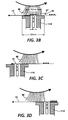
- the UCA is placed under the belt in the cleaning nip (formed by the brush 80 and belt 10) as shown in Figure 3A, as opposed to the prenip zone or post nip zone.
- the toner on the brush fiber is picked up on the very tips of the brush fibers.
- Figure 3B shows the UCA in the middle of the cleaning nip.
- the toner is levitated in the cleaning nip. Capturing this toner that is levitated on the fiber tips has several important advantages.
- the brush interference with the photoreceptor is less; this reduces the brush set and increases brush life.
- the brush voltage is less; this aids in reducing the size to the "match head”.
- the brush rpm is less; this reduces toner emissions from the brush. It has been found that the width of the active zone (the excitation zone) must be smaller than the cleaning nip width. For example, the active zone should be about half the width of the cleaning nip.
- FIG. 1A shows a schematic of a cleaner brush fiber 86 showing a typical "match head " of toner 83 on the fiber 86.
- the brush fibers 86 become loaded with toner during cleaning and cannot be adequately detoned, with a detoning roll, due to the fiber compression that occurs during detoning which tends to trap toner in the fibers (see Figure 1B).
- the reason for this is that during cleaning, the toner 83 on the fiber (i.e. match head) does not just build up on the fiber tip 81, but builds upon the fiber 86 towards the core 82 of the brush as shown in Figure 1C.
- a miniature brush with a high density of fibers the compression of fibers makes it very difficult to remove toner using simply a detoning roll.
- the length L is greater than about 300 ⁇ and the diameter is about 90 ⁇ .
- a typical brush fiber has a diameter of about 33 ⁇ .
- Figures 2A and 2B are graphical depictions of the diameter of the "match head” 83 versus the length of the “match head” to show the effects of brush rotational speed (rpm) on match head length L for developed mass per unit area (DMA) of 0.40 and without UCA.
- the smallest “match head” (the smallest L value) is the best and occurs at the highest rpm.
- the reason that the smallest L values occur at higher speeds is that the toner image A is spread out over the brush fibers 86 as shown by image B on the brush 80.
- the width W B of the image B on the brush 80 is typically twice the width W A of the image A on the photoreceptor 10.
- This image width W B on the brush 80 is dependent upon the rotational speed of the brush 80 with respect to the speed of the photoreceptor belt 10. Even with optimized cleaner set points, the toner 87 extends down the fibers 86 (towards the core 82) too far, and the toner 87 on the fibers 86 is not detoned well enough.
- Figure 2A shows a detoning efficiency of 76% at the higher brush rpm of 200, and a shorter match head length L of about 275 ⁇ m.
- Figure 2B shows a detoning efficiency of 45% at the lower brush rpm of 50, and a longer "match head” length L of about 550 ⁇ m.
- the shorter "match head” length (shown in Figure 6) and higher detoning efficiency was achieved by increasing the brush rpm.
- the "match head" length can be decreased to about 100 ⁇ m (see Fig.6) and the detoning efficiency approaches 100%.
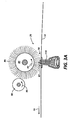
- FIG. 3 shows a schematic elevational view of the ultrasonic transducer 110 location in the cleaner brush nip 88.
- the purpose of the ultrasonic transducer 110 is to loosen the toner particles 87 remaining on the photoreceptor 10 during a cleaning cycle, and allow the brush 80, rotating in a counterclockwise direction shown by arrow 85, to remove the airborne toner particles 87, in the cleaning brush nip 88, by attracting the particles to the brush fiber tips.
- UCA ultrasonic cleaning assist
- the typical interference of the brush fibers with the imaging surface of the photoreceptor, without an ultrasonic transducer 110, is about 2mm.
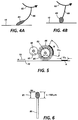
- An example of such a brush fiber 86 is shown in Figure 4A.
- the brush fiber/imaging surface interference can be reduced to about 1mm.
- An example of such a brush fiber 86 with less interference is shown in Figure 4B.
- Ultrasonic enhanced cleaning, properly located, enables reduced brush interference and therefore less fiber (stem) area contact with the photoreceptor 10. (See Figure 4B).
- the interference measurement is the length of the brush fibers extending past the photoreceptor 10 surface if the fibers 86 were straight rather than bent due to contact with the photoreceptor surface. It is noted that the interference parameter of approximately 1mm can be reduced further depending upon the tolerances of the apparatus.
- the ultrasonic transducer 110 is located in the (center of the) brush cleaning nip 88, (i.e. not in the post nip zone nor in the prenip zone) opposite the brush cleaner 80 making vibrational contact with the underside of the photoreceptor belt 10. (i.e. the brush contact point or nip is directly opposite the transducer tip).
- This location of the UCA causes the toner picked up by the brush fibers 86 to collect at the very tip 81 of the fibers 86.
- a detoning roll 90 rotating in the counterclockwise direction shown by arrow 85, removes the toner from the brush fiber tips easily for high detoning efficiency.
- the transducer parameters such as location and vibrational energy are important because too much vibration can levitate the toner too much, and cause the toner 87 to move too far into the brush. This affects detoning efficiency because now the toner on the fiber tips 81 extends too far down into the fiber. When this occurs the "match head" 83 becomes elongated on the fiber 86 and detoning efficiency is reduced.
- the airborne toner 87 is captured on the brush fibers creating a small spherically shaped match head 83, which is desired for efficient detoning of the brush.
- An example of a "match head" length and diameter that allows for efficient detoning of the brush fiber 86 is about 100 ⁇ m as shown in Figure 6.
- the present invention describes placing an ultrasonic transducer under the photoreceptor belt.
- the transducer is positioned such that it is located directly opposite the cleaning nip of the brush cleaner.
- the transducer reduces the toner to photoreceptor surface adhesion, thereby allowing the brush to operate at reduced interference and voltage.
- the reduced interference and voltage results in toner being collected only at the very tips of the brush fibers thus, allowing more effective detoning of the brush.
Landscapes
- Physics & Mathematics (AREA)
- General Physics & Mathematics (AREA)
- Cleaning In Electrography (AREA)
- Nozzles (AREA)
Abstract
Description
- This invention relates generally to an apparatus for cleaning toner from an imaging member, and more particularly, concerns an apparatus employing an ultrasonic transducer whereby efficiency of detoning of a cleaner brush is optimised.
- A commercially successful mode of cleaning employed on automatic xerographic devices utilizes a brush with soft conductive fiber bristles or with insulative soft bristles which have suitable triboelectric characteristics. While the bristles are soft for the insulative brush, they provide sufficient mechanical force to dislodge residual toner particles from a charge retentive surface of an imaging member. In the case of the conductive brush, the brush is usually electrically biased to provide an electrostatic force for toner detachment from the charge retentive surface. Toner particles adhere to the fibers (i.e. bristles) of the brush after the charge retentive surface has been cleaned.
- The process of removing toner from these types of cleaner brushes can be accomplished in many ways. Typically, brush cleaners, use flicker bars to provide the detoning function. A flicker bar is usually a thin long bar with a controlled amount of interference (engagement) with the brush fibers. When the fibers encounter the flicker bar, the fibers bend and the impact dislodges toner particles adhering to the fibers. Once released, these particles may be carried away by an airstream to a toner filter or separator. In some electrostatic brush cleaners the toner is removed from the brush with a rotating biased detoning roll. The disadvantage of this method is that as the size of cleaner brushes decrease in diameter, they can not be properly detoned in this manner. This results in partial detoning of the fibers and a gradual accumulation of toner in the brush. When the amount of toner accumulated in the brush exceeds a critical level, a severe cleaning failure can occur.
- US-A-5,030,999 discloses a piezoelectric transducer (PZT) device operating at a relatively high frequency coupled to the backside of a somewhat flexible imaging surface to cause localized vibration at a predetermined amplitude, and is positioned in close association with the imaging surface cleaning function, whereby residual toner and debris (hereinafter referred to as simply toner) is fluidized for enhanced electrostatic discharge of the toner and/or imaging surface and released from the mechanical forces adhering the toner to the imaging surface.
- US-A-4,833,503 discloses a multi-color printer using a sonic toner release development system to provide either partial or full color copies with minimal degradation of developed toner patterns by subsequent over-development with additional colors and minimal back contamination of developer materials. After developing of the last color image, the composite color image is transferred to a copy sheet. Development is accomplished by vibrating the surface of a toner carrying member and thereby reducing the net force of adhesion of toner to the surface of the toner carrying member.
- US-A-4,111,546 discloses an electrostatographic reproducing apparatus and process including a system for ultrasonically cleaning residual material from the imaging surface. Ultrasonic vibratory energy is applied to the air space adjacent the imaging surface to excite the air molecules for dislodging the residual material from the imaging surface. Preferably pneumatic cleaning is employed simultaneously with the ultrasonic cleaning. Alternatively a conventional mechanical cleaning system is augmented by localized vibration of the imaging surface at the cleaning station which are provided from behind the imaging surface.
- The present invention provides an apparatus for cleaning particles from a surface. The apparatus comprises a rotatable brush contacting a side of the surface to form a cleaning nip to remove particles from the surface thereat; and vibrational means located directly opposed from the cleaning nip with the surface being interposed between the rotatable brush and the vibrational means. The vibrational means reduces surface adhesion between the particles and the surface to facilitate removal therefrom by the rotatable brush.
- Pursuant to another aspect of the present invention, there is provided a printing machine incorporating the aforementioned apparatus.
- Other features of the present invention will become apparent as the following description proceeds and upon reference to the drawings, in which:
- Figure 1A is a schematic view of a cleaner brush fiber showing a typical "match head" of toner on the fiber tip;
- Figure 1B is a schematic view of the brush fibers interfering with the detoning roll;
- Figure 1C is a schematic view showing brush fibers at the beginning and end of the detoning operation;
- Figures 2A and 2B are graphical depictions of the diameter of the "match head" versus the length of the "match head", showing the effects of brush rotation speed (in rpm) on match head size;
- Figure 3A is a schematic elevational view of an embodiment of the invention, with the ultrasonic transducer located opposite the cleaner brush nip;
- Figure 3B is an enlarged partial schematic view of the embodiment of Fig.3A;
- Figure 3C is a schematic view of a cleaning apparatus with the ultrasonic transducer at the post nip zone;
- Figure 3D is a schematic view of a cleaning apparatus with the ultrasonic transducer at the prenip zone;
- Figure 4A is a schematic view of a typical fiber in interference with the photoreceptor;
- Figure 4B is a schematic view of a brush fiber requiring less interference with the photoreceptor due to the ultrasonic cleaning assist (UCA) in accordance with the invention;
- Figure 5 is a schematic view showing the relative size of a toner image on the photoreceptor and the toner spread on the brush fibers;
- Figure 6 is a schematic view of a "match head" on the brush fiber that occurs with the present invention using an ultrasonic transducer; and
- Figure 7 is a schematic illustration of a printing apparatus incorporating the cleaning apparatus of the present invention.
- An exemplary electrostatic printing machine is illustrated in Fig.7. A detailed description of the various processing stations of the machine has been omitted from the present disclosure, for brevity, as they are well known in the art. For a description of the machine of Figure 7, reference is made to US application SN 08/352,939, a copy of which was filed with the present application. In the machine of Fig.7, residual toner and debris remaining on
photoreceptor belt 10 after each copy is made, may be removed at cleaning station F with a brush, blade or other type ofcleaning system 70. - The present invention employs an ultrasonic cleaning assist (UCA) device (e.g. ultrasonic transducer) to assist in detoning an ESB (i.e. electrostatic brush) or an insulative brush cleaner in addition to assisting in the cleaning of the imaging surface. This is specifically useful in detoning a miniature ESB. Normally, such miniature brushes are 25 mm in diameter, have a weave density of about 80,000 fibers/in2 (13,000 fibres/cm2), and a 7 mm pile height. These brushes can not be detoned properly with a
detoning roll 90 due to tight compression of the densely packedfibers 86 against the detoning roll as shown in Figure 1B. Thetoner 87 that is not at the tip of thefibers 86 is shielded byother fibers 86 and does not "see" the detoning roll electric field. This occurs when the "match head" 83 is too long: Figure 1C shows this detoning step when the "match head" is too long, and only the tip of the fiber is detoned. The accumulation of the toner left on the fiber causes toner to build up in the brush. This results in toner emissions from the cleaner, and cleaning failures. - However, by using an UCA, the size of the "match head" on the fiber is controlled, and emissions from the cleaner and cleaning failures are alleviated. An important part of the effectiveness of the present invention is the critical location of the UCA device in relation to the cleaner brush. The UCA is placed under the belt in the cleaning nip (formed by the
brush 80 and belt 10) as shown in Figure 3A, as opposed to the prenip zone or post nip zone. By placing the UCA in the middle of the cleaning nip (see Figure 3B), as opposed to the prenip zone, or the post nip zone as shown in Figures 3C and 3D respectively, the toner on the brush fiber is picked up on the very tips of the brush fibers. Figure 3B shows the UCA in the middle of the cleaning nip. In this case, the toner is levitated in the cleaning nip. Capturing this toner that is levitated on the fiber tips has several important advantages. First, the brush interference with the photoreceptor is less; this reduces the brush set and increases brush life. Second, the brush voltage is less; this aids in reducing the size to the "match head". Third, the brush rpm is less; this reduces toner emissions from the brush. It has been found that the width of the active zone (the excitation zone) must be smaller than the cleaning nip width. For example, the active zone should be about half the width of the cleaning nip. - It is important to note that a large area ultrasonic transducer or
vibrator 110 cannot be placed correctly in the middle of the cleaning nip of a small brush cleaner, i.e., the active zone of a largeultrasonic transducer 110 is too large extending beyond thecleaning nip 88 of thebrush 80. This effect is illustrated in Figures 3C and 3D. For example, suppose theultrasonic transducer 110 is in the prenip zone as shown in Figure 3D, or the active zone of theultrasonic transducer 110 is large and extends into this area. This is an unsatisfactory location because there are no fibers to pick up the charged toner that is levitated momentarily. These toner particles return to the photoreceptor surface and adhere more strongly. This higher adhesion is created by the charge particles rotating and attaching the higher charged region on the toner particles to thephotoreceptor 10. These particles adhere more strongly and cause inadequate cleaning or cleaning failures because the brush cannot clean these toner particles. With the ultrasonic device in the post nip zone, as shown in Fig. 3C, most of the excitation field (the active zone) is outside of the cleaning nip. Thus the effect of the UCA is lost. - Reference is now made to Figure 1A, which shows a schematic of a
cleaner brush fiber 86 showing a typical "match head " oftoner 83 on thefiber 86. In a miniature ESB cleaner, for example, thebrush fibers 86 become loaded with toner during cleaning and cannot be adequately detoned, with a detoning roll, due to the fiber compression that occurs during detoning which tends to trap toner in the fibers (see Figure 1B). The reason for this is that during cleaning, thetoner 83 on the fiber (i.e. match head) does not just build up on thefiber tip 81, but builds upon thefiber 86 towards thecore 82 of the brush as shown in Figure 1C. In a miniature brush with a high density of fibers, the compression of fibers makes it very difficult to remove toner using simply a detoning roll. [In Fig.1A an example of a "match head" that causes difficulty in detoning is shown: the length L is greater than about 300µ and the diameter is about 90µ. A typical brush fiber has a diameter of about 33µ.] - With continued reference to Figure 1B, when the
brush 80 comes into contact with thedetoning roll 90, thebrush fibers 86 are compressed and the toner 83 (i.e. in the elongated match head configuration of Figure 1C) that is not near thefiber tip 81 is not (completely) detoned. Thetoner 87 on the fibers that is not near thetips 81 of the fibers is shielded by theother fibers 86 and does not make contact with the field of the detoning roll. Under these conditions, thebrush fibers 86 gradually load up withtoner 87 causing cleaning failures and increasing toner emissions. - Reference is now made to Figures 2A and 2B, which are graphical depictions of the diameter of the "match head" 83 versus the length of the "match head" to show the effects of brush rotational speed (rpm) on match head length L for developed mass per unit area (DMA) of 0.40 and without UCA. The smallest "match head" (the smallest L value) is the best and occurs at the highest rpm. Referring now to Figure 5, the reason that the smallest L values occur at higher speeds is that the toner image A is spread out over the
brush fibers 86 as shown by image B on thebrush 80. The width WB of the image B on thebrush 80 is typically twice the width WA of the image A on thephotoreceptor 10. This image width WB on thebrush 80 is dependent upon the rotational speed of thebrush 80 with respect to the speed of thephotoreceptor belt 10. Even with optimized cleaner set points, thetoner 87 extends down the fibers 86 (towards the core 82) too far, and thetoner 87 on thefibers 86 is not detoned well enough. - Referring once again to Figures 2A and 2B, some examples of the dependency of the detoning efficiency on the "match head" length L, and rotational speed of the brush are plotted. Figure 2A shows a detoning efficiency of 76% at the higher brush rpm of 200, and a shorter match head length L of about 275 µm. Whereas, Figure 2B shows a detoning efficiency of 45% at the lower brush rpm of 50, and a longer "match head" length L of about 550 µm. Thus, the shorter "match head" length (shown in Figure 6) and higher detoning efficiency was achieved by increasing the brush rpm. This is the best that one can achieve for a toner input density to the cleaner of 0.4 mg/cm2 without using the ultrasonic cleaning assist. By employing the UCA, the "match head" length can be decreased to about 100 µm (see Fig.6) and the detoning efficiency approaches 100%.
- Reference is now made to Figure 3, which shows a schematic elevational view of the
ultrasonic transducer 110 location in the cleaner brush nip 88. The purpose of the ultrasonic transducer 110 (or ultrasonic cleaning assist i.e. UCA) in the present invention, is to loosen thetoner particles 87 remaining on thephotoreceptor 10 during a cleaning cycle, and allow thebrush 80, rotating in a counterclockwise direction shown byarrow 85, to remove theairborne toner particles 87, in the cleaning brush nip 88, by attracting the particles to the brush fiber tips. Thus, allowing the fibers of thebrush 80 to clean at a small interference with thephotoreceptor 10 and with a low bias voltage. - The typical interference of the brush fibers with the imaging surface of the photoreceptor, without an
ultrasonic transducer 110, is about 2mm. An example of such abrush fiber 86 is shown in Figure 4A. With the use of anultrasonic transducer 110, as in the present invention, the brush fiber/imaging surface interference can be reduced to about 1mm. An example of such abrush fiber 86 with less interference is shown in Figure 4B. Ultrasonic enhanced cleaning, properly located, enables reduced brush interference and therefore less fiber (stem) area contact with thephotoreceptor 10. (See Figure 4B). (The interference measurement is the length of the brush fibers extending past thephotoreceptor 10 surface if thefibers 86 were straight rather than bent due to contact with the photoreceptor surface.) It is noted that the interference parameter of approximately 1mm can be reduced further depending upon the tolerances of the apparatus. - With reference to Figure 3A, the
ultrasonic transducer 110 is located in the (center of the) brush cleaning nip 88, (i.e. not in the post nip zone nor in the prenip zone) opposite thebrush cleaner 80 making vibrational contact with the underside of thephotoreceptor belt 10. (i.e. the brush contact point or nip is directly opposite the transducer tip). This location of the UCA causes the toner picked up by thebrush fibers 86 to collect at thevery tip 81 of thefibers 86. Adetoning roll 90, rotating in the counterclockwise direction shown byarrow 85, removes the toner from the brush fiber tips easily for high detoning efficiency. The transducer parameters such as location and vibrational energy are important because too much vibration can levitate the toner too much, and cause thetoner 87 to move too far into the brush. This affects detoning efficiency because now the toner on thefiber tips 81 extends too far down into the fiber. When this occurs the "match head" 83 becomes elongated on thefiber 86 and detoning efficiency is reduced. - With the
brush fibers 86 just touching the photoreceptor surface (see Figure 4B), theairborne toner 87 is captured on the brush fibers creating a small sphericallyshaped match head 83, which is desired for efficient detoning of the brush. An example of a "match head" length and diameter that allows for efficient detoning of thebrush fiber 86 is about 100 µm as shown in Figure 6. - Thus, a cleaner with low brush interference and bias voltage becomes viable, with the UCA to loosen the
toner 87 on thephotoreceptor 10. Other implications are also possible. If the residual toner after transfer contains a lot of fines (i.e. 2 to 4 µm toners), the UCA will help in the removal of this toner. Also, with less brush to photoreceptor interference, brush set is dramatically reduced. A further benefit of reduced interference is the significant reduction in brush set during on/off cycles. Also, with less interference, photoreceptor drag and abrasion are reduced. - In recapitulation, the present invention describes placing an ultrasonic transducer under the photoreceptor belt. The transducer is positioned such that it is located directly opposite the cleaning nip of the brush cleaner. The transducer reduces the toner to photoreceptor surface adhesion, thereby allowing the brush to operate at reduced interference and voltage. The reduced interference and voltage results in toner being collected only at the very tips of the brush fibers thus, allowing more effective detoning of the brush.
Claims (10)
- An apparatus (70) for cleaning particles (87) from a member (10), comprising:a rotatable brush (80) contacting a surface of the member (10) to form a cleaning nip (88) to remove particles from the surface thereat; andvibrational means (110) located opposed from the cleaning nip (88) with the member (10) being interposed between said rotatable brush (80) and said vibrational means (110), said vibrational means reducing surface adhesion of the particles (87) to the surface to facilitate removal therefrom by said rotatable brush (80).
- An apparatus as recited in claim 1, wherein the cleaning nip comprises a post nip zone, a prenip zone and a center nip.
- An apparatus as recited in claim 2, wherein said vibrational means (110) contacts a surface of the member (10) opposed from the first mentioned surface, and opposed to the center nip of the cleaning nip.
- An apparatus as recited in claim 1, 2 or 3, further comprising a device (90) for detoning said rotatable brush (80).
- An apparatus as recited in any of the preceding claims, wherein said rotatable brush (80) comprises:a core (82); anda multiplicity of fibers (86) extending outwardly from said core.
- An apparatus as recited in claim 5, wherein said fibers comprise:fixed ends coupled to said core (82); andfree ends opposed from the fixed ends, the free ends having fiber tips (81) that contact the surface of the member (10).
- An apparatus as recited in any of the preceding claims, wherein the interference between said fi bers (86) of said brush (80) and the surface is about 1 mm.
- An apparatus as recited in any of the preceding claims, wherein said vibrational means (110) comprises a narrow surface area contacting the surface for causing localized vibration of the member (10).
- An apparatus as recited in any of the preceding claims, wherein said vibrational means (110) comprises an ultrasonic transducer.
- A printing machine having an apparatus (70) for cleaning particles (87) from a surface, according to any of the preceding claims.
Applications Claiming Priority (2)
| Application Number | Priority Date | Filing Date | Title |
|---|---|---|---|
| US35293994A | 1994-12-09 | 1994-12-09 | |
| US352939 | 1994-12-09 |
Publications (2)
| Publication Number | Publication Date |
|---|---|
| EP0716359A1 true EP0716359A1 (en) | 1996-06-12 |
| EP0716359B1 EP0716359B1 (en) | 2000-03-15 |
Family
ID=23387096
Family Applications (1)
| Application Number | Title | Priority Date | Filing Date |
|---|---|---|---|
| EP95308918A Expired - Lifetime EP0716359B1 (en) | 1994-12-09 | 1995-12-08 | Ultrasonic transducer for brush detoning assist |
Country Status (4)
| Country | Link |
|---|---|
| US (1) | US5576822A (en) |
| EP (1) | EP0716359B1 (en) |
| JP (1) | JP3844803B2 (en) |
| DE (1) | DE69515609T2 (en) |
Cited By (3)
| Publication number | Priority date | Publication date | Assignee | Title |
|---|---|---|---|---|
| EP0816945A1 (en) * | 1996-06-27 | 1998-01-07 | Xerox Corporation | Cleaning apparatus |
| CN109847989A (en) * | 2019-02-28 | 2019-06-07 | 天科新能源有限责任公司 | A double-sided coating device for lithium battery materials |
| EP4080856A1 (en) * | 2021-04-21 | 2022-10-26 | Nokia Technologies Oy | Electronic device with dust mitigation |
Families Citing this family (8)
| Publication number | Priority date | Publication date | Assignee | Title |
|---|---|---|---|---|
| US5689791A (en) * | 1996-07-01 | 1997-11-18 | Xerox Corporation | Electrically conductive fibers |
| US5659849A (en) * | 1996-07-03 | 1997-08-19 | Xerox Corporation | Biased toner collection roll for an ultrasonically assisted cleaning blade |
| US5864741A (en) * | 1997-04-17 | 1999-01-26 | Xerox Corporation | Single brush cleaner with collection roll and ultrasonic cleaning assist |
| US6203151B1 (en) | 1999-06-08 | 2001-03-20 | Hewlett-Packard Company | Apparatus and method using ultrasonic energy to fix ink to print media |
| US6169872B1 (en) * | 1999-09-28 | 2001-01-02 | Xerox Corporation | Electrostatic cleaning belt brush |
| JP2001246331A (en) * | 2000-03-08 | 2001-09-11 | Sharp Corp | Cleaning equipment |
| DE10027203A1 (en) | 2000-05-31 | 2001-12-20 | Oce Printing Systems Gmbh | Device and method for cleaning and regenerating an image carrier in electrographic printing or copying using liquid colorants |
| JP5574220B2 (en) * | 2010-02-08 | 2014-08-20 | 株式会社リコー | Cleaning device, belt device, and image forming apparatus |
Citations (5)
| Publication number | Priority date | Publication date | Assignee | Title |
|---|---|---|---|---|
| US4111546A (en) | 1976-08-26 | 1978-09-05 | Xerox Corporation | Ultrasonic cleaning apparatus for an electrostatographic reproducing machine |
| JPS57100460A (en) * | 1980-12-15 | 1982-06-22 | Toshiba Corp | Cleaning device for forming surface of latent image |
| US4833503A (en) | 1987-12-28 | 1989-05-23 | Xerox Corporation | Electronic color printing system with sonic toner release development |
| US4987456A (en) * | 1990-07-02 | 1991-01-22 | Xerox Corporation | Vacuum coupling arrangement for applying vibratory motion to a flexible planar member |
| US5030999A (en) | 1989-06-19 | 1991-07-09 | Xerox Corporation | High frequency vibratory enhanced cleaning in electrostatic imaging devices |
Family Cites Families (7)
| Publication number | Priority date | Publication date | Assignee | Title |
|---|---|---|---|---|
| JP2754580B2 (en) * | 1988-07-29 | 1998-05-20 | ミノルタ株式会社 | Cleaner |
| US5065194A (en) * | 1990-05-29 | 1991-11-12 | Eastman Kodak Company | Piezo film cleaner |
| US5010369A (en) * | 1990-07-02 | 1991-04-23 | Xerox Corporation | Segmented resonator structure having a uniform response for electrophotographic imaging |
| US5025291A (en) * | 1990-07-02 | 1991-06-18 | Zerox Corporation | Edge effect compensation in high frequency vibratory energy producing devices for electrophotographic imaging |
| US5005054A (en) * | 1990-07-02 | 1991-04-02 | Xerox Corporation | Frequency sweeping excitation of high frequency vibratory energy producing devices for electrophotographic imaging |
| US5153658A (en) * | 1991-08-09 | 1992-10-06 | Xerox Corporation | Mac cleaner brush film control |
| US5282005A (en) * | 1993-01-13 | 1994-01-25 | Xerox Corporation | Cross process vibrational mode suppression in high frequency vibratory energy producing devices for electrophotographic imaging |
-
1995
- 1995-12-01 JP JP31392995A patent/JP3844803B2/en not_active Expired - Fee Related
- 1995-12-08 EP EP95308918A patent/EP0716359B1/en not_active Expired - Lifetime
- 1995-12-08 DE DE69515609T patent/DE69515609T2/en not_active Expired - Lifetime
-
1996
- 1996-03-29 US US08/625,788 patent/US5576822A/en not_active Expired - Lifetime
Patent Citations (5)
| Publication number | Priority date | Publication date | Assignee | Title |
|---|---|---|---|---|
| US4111546A (en) | 1976-08-26 | 1978-09-05 | Xerox Corporation | Ultrasonic cleaning apparatus for an electrostatographic reproducing machine |
| JPS57100460A (en) * | 1980-12-15 | 1982-06-22 | Toshiba Corp | Cleaning device for forming surface of latent image |
| US4833503A (en) | 1987-12-28 | 1989-05-23 | Xerox Corporation | Electronic color printing system with sonic toner release development |
| US5030999A (en) | 1989-06-19 | 1991-07-09 | Xerox Corporation | High frequency vibratory enhanced cleaning in electrostatic imaging devices |
| US4987456A (en) * | 1990-07-02 | 1991-01-22 | Xerox Corporation | Vacuum coupling arrangement for applying vibratory motion to a flexible planar member |
Non-Patent Citations (3)
| Title |
|---|
| GROSS R A: "ACOUSTIC ASSIST ACTIVE MATRIX PHOTORECEPTOR WEB SURFACE CLEANER", XEROX DISCLOSURE JOURNAL, vol. 19, no. 6, pages 493/494, XP000484373 * |
| MANCINE G J: "ACOUSTICAL ELECTROSTATIC BRUSH CLEANER ASSIST", XEROX DISCLOSURE JOURNAL, vol. 18, no. 3, pages 249 - 250, XP000367970 * |
| PATENT ABSTRACTS OF JAPAN vol. 006, no. 188 (P - 144) 28 September 1982 (1982-09-28) * |
Cited By (5)
| Publication number | Priority date | Publication date | Assignee | Title |
|---|---|---|---|---|
| EP0816945A1 (en) * | 1996-06-27 | 1998-01-07 | Xerox Corporation | Cleaning apparatus |
| CN109847989A (en) * | 2019-02-28 | 2019-06-07 | 天科新能源有限责任公司 | A double-sided coating device for lithium battery materials |
| CN109847989B (en) * | 2019-02-28 | 2021-03-12 | 天科新能源有限责任公司 | A double-sided coating device for lithium battery materials |
| EP4080856A1 (en) * | 2021-04-21 | 2022-10-26 | Nokia Technologies Oy | Electronic device with dust mitigation |
| US12026020B2 (en) | 2021-04-21 | 2024-07-02 | Nokia Technologies Oy | Dust mitigation |
Also Published As
| Publication number | Publication date |
|---|---|
| JPH08224502A (en) | 1996-09-03 |
| US5576822A (en) | 1996-11-19 |
| DE69515609D1 (en) | 2000-04-20 |
| JP3844803B2 (en) | 2006-11-15 |
| DE69515609T2 (en) | 2000-08-17 |
| EP0716359B1 (en) | 2000-03-15 |
Similar Documents
| Publication | Publication Date | Title |
|---|---|---|
| EP0716359B1 (en) | Ultrasonic transducer for brush detoning assist | |
| JPH03500343A (en) | Cleaning device with magnetic toner remover | |
| JPH10301409A (en) | Electric bias control for transfer roller | |
| EP0709751B1 (en) | Apparatus for cleaning particles from a surface | |
| CA2229167C (en) | Single brush cleaner with collection roll and ultrasonic cleaning assist | |
| JPS633313B2 (en) | ||
| JPH06324610A (en) | Brush cleaning device | |
| EP0463399A2 (en) | Sweep and vacuum xerographic cleaning method and apparatus | |
| US5659849A (en) | Biased toner collection roll for an ultrasonically assisted cleaning blade | |
| JP2000003118A (en) | Photoreceptor cleaning device and method therefor | |
| JP3587615B2 (en) | Electrophotographic equipment | |
| EP1519245A2 (en) | A rotating flicker bar for cleaning a rotating cleaner roll and for transmitting power to the cleaner roll | |
| JP2001013764A (en) | Charger cleaning device | |
| JP5463135B2 (en) | Transfer belt cleaning device | |
| US5878316A (en) | Cleaning mechanism for a reproduction apparatus | |
| JPS6057879A (en) | Cleaning device | |
| JP2911717B2 (en) | Separation device and image forming apparatus using this separation device | |
| JP3348554B2 (en) | Photoconductor cleaning device | |
| JP4218330B2 (en) | Image forming apparatus | |
| JPH1195549A (en) | Image forming device | |
| JPH0546055A (en) | Cleaning device | |
| JPH0764456A (en) | Electrophotographic printer cleaning device | |
| JP2570831B2 (en) | Fur brush cleaning mechanism of recording device | |
| JP2586824B2 (en) | Electrophotographic recording device | |
| JPH0314676Y2 (en) |
Legal Events
| Date | Code | Title | Description |
|---|---|---|---|
| PUAI | Public reference made under article 153(3) epc to a published international application that has entered the european phase |
Free format text: ORIGINAL CODE: 0009012 |
|
| AK | Designated contracting states |
Kind code of ref document: A1 Designated state(s): DE FR GB |
|
| 17P | Request for examination filed |
Effective date: 19961212 |
|
| 17Q | First examination report despatched |
Effective date: 19980730 |
|
| GRAG | Despatch of communication of intention to grant |
Free format text: ORIGINAL CODE: EPIDOS AGRA |
|
| GRAG | Despatch of communication of intention to grant |
Free format text: ORIGINAL CODE: EPIDOS AGRA |
|
| GRAH | Despatch of communication of intention to grant a patent |
Free format text: ORIGINAL CODE: EPIDOS IGRA |
|
| GRAH | Despatch of communication of intention to grant a patent |
Free format text: ORIGINAL CODE: EPIDOS IGRA |
|
| GRAA | (expected) grant |
Free format text: ORIGINAL CODE: 0009210 |
|
| AK | Designated contracting states |
Kind code of ref document: B1 Designated state(s): DE FR GB |
|
| REF | Corresponds to: |
Ref document number: 69515609 Country of ref document: DE Date of ref document: 20000420 |
|
| ET | Fr: translation filed | ||
| PLBE | No opposition filed within time limit |
Free format text: ORIGINAL CODE: 0009261 |
|
| STAA | Information on the status of an ep patent application or granted ep patent |
Free format text: STATUS: NO OPPOSITION FILED WITHIN TIME LIMIT |
|
| 26N | No opposition filed | ||
| REG | Reference to a national code |
Ref country code: GB Ref legal event code: IF02 |
|
| REG | Reference to a national code |
Ref country code: GB Ref legal event code: 746 Effective date: 20050809 |
|
| PGFP | Annual fee paid to national office [announced via postgrant information from national office to epo] |
Ref country code: FR Payment date: 20101224 Year of fee payment: 16 |
|
| PGFP | Annual fee paid to national office [announced via postgrant information from national office to epo] |
Ref country code: GB Payment date: 20101208 Year of fee payment: 16 |
|
| PGFP | Annual fee paid to national office [announced via postgrant information from national office to epo] |
Ref country code: DE Payment date: 20101130 Year of fee payment: 16 |
|
| GBPC | Gb: european patent ceased through non-payment of renewal fee |
Effective date: 20111208 |
|
| REG | Reference to a national code |
Ref country code: FR Ref legal event code: ST Effective date: 20120831 |
|
| REG | Reference to a national code |
Ref country code: DE Ref legal event code: R119 Ref document number: 69515609 Country of ref document: DE Effective date: 20120703 |
|
| PG25 | Lapsed in a contracting state [announced via postgrant information from national office to epo] |
Ref country code: GB Free format text: LAPSE BECAUSE OF NON-PAYMENT OF DUE FEES Effective date: 20111208 Ref country code: DE Free format text: LAPSE BECAUSE OF NON-PAYMENT OF DUE FEES Effective date: 20120703 |
|
| PG25 | Lapsed in a contracting state [announced via postgrant information from national office to epo] |
Ref country code: FR Free format text: LAPSE BECAUSE OF NON-PAYMENT OF DUE FEES Effective date: 20120102 |